Burkert 6517 User manual

Pneumatikventil
Vor der Inbetriebnahme
Anschlüsse,SpannungundBetriebsdruckprüfen.Max.
Betriebsdaten (siehe Typschild) nicht überschreiten.
Anschluss 1 nicht mit Anschluss 3 bzw. 5 vertauschen.
Bei elektrischem Betrieb muss die Handbetätigung
entriegelt sein.
Störungen
*Zugeringe Druckdifferenzzwischen denAnschlüssen
1 und 3/5 durch zu kleine oder verschmutzte
Geräuschdämpfer.
*Querschnitt der Druckversorgung (Anschluss 1) nicht
ausreichend.
*Schlauchinnendurchmesserfür1/3/5Anschlüssemind.
6 mm, um einwandfreies Umschalten der Ventile zu
gewährleisten.
*Handbetätigung nicht entriegelt.
*EntlüftungsanschlüssederVorsteuerungen(G1/8)auf
den Anschlussmodulen dürfen nicht verchlossen sein.
Vorsicht: Bei unter Druck stehendem System keine
Leitungen lösen.
Bestimmungsgemässer Gebrauch
DerAnwendermusszurSicherheiteinereinwandfreien
Funktion und langen Lebensdauer des Ventils diese
Betriebsanleitung beachten sowie die
Einsatzbedingungen und zulässigen Daten gemäss
Datenblatt einhalten.
DieEinsatzplanungundderBetriebdesGeräteshaben
nachdenallgemeinenRegeln der Technikzuerfolgen.
Unbeabsichtigte Betätigungen oder nicht zugelassene
BeeinträchtigungensinddurchgeeigneteMassnahmen
zu verhindern.
Ventilaufbau
* Antriebe: - Magnetantrieb
- Pneumatische Ansteuerung
*VentilgehäusemitMembranund Sitzdichtungen(5/2)
*Arbeitsanschlüsse2(B)/4(A)nachNamurFlanschbild
sowie Ver- und Entsorgungsanschlüsse 1 (P)/3 (R)/5
(S) mit G1/4-Innengewinde.
Medium
Gefilterte Druckluft, geölt oder ungeölt.
Dichtwerkstoffe:
BP = Perbunan und Polyurethan für 3/2- und 5/2-
Ventile
Der Steuerdruck bei pneumatischer Ansteuerung ist
unabhängig vom Druck des Durchflußmediums und
von der Art des Antriebes; er darf maximal 8 bar
betragen.
Achtung !
Zulässigen Druckbereich auf Typschild beachten.
Druckdifferenz min. 2 bar zwischen Anschluß 1 und 3/
5.
Temperatur Medium: max. + 50 °C.
Temperatur Umgebung: max. + 55 °C.
Einbau
Einbaulagebeliebig;Empfehlung:Nachobenweisendes
Magnetsystem.
Elektrischer Anschluß
Spannung und Stromart auf Typschild beachten.
Spannungstoleranz +/-10%.AnschlußmitBÜRKERT-
Gerätesteckdose 2508 (DIN43650), Schutzart IP65.
Wird die Gerätesteckdose DIN43650 so
aufgebaut, dass die Schraube nach oben
steht, fügen Sie eine Dichtung aus einem
mit ihrem Prozess kompatiblen Werkstoff
unter dem Schraubenkopf ein.
Wartung
Das Gerät arbeitet unter normalen Bedingungen
wartungsfrei.
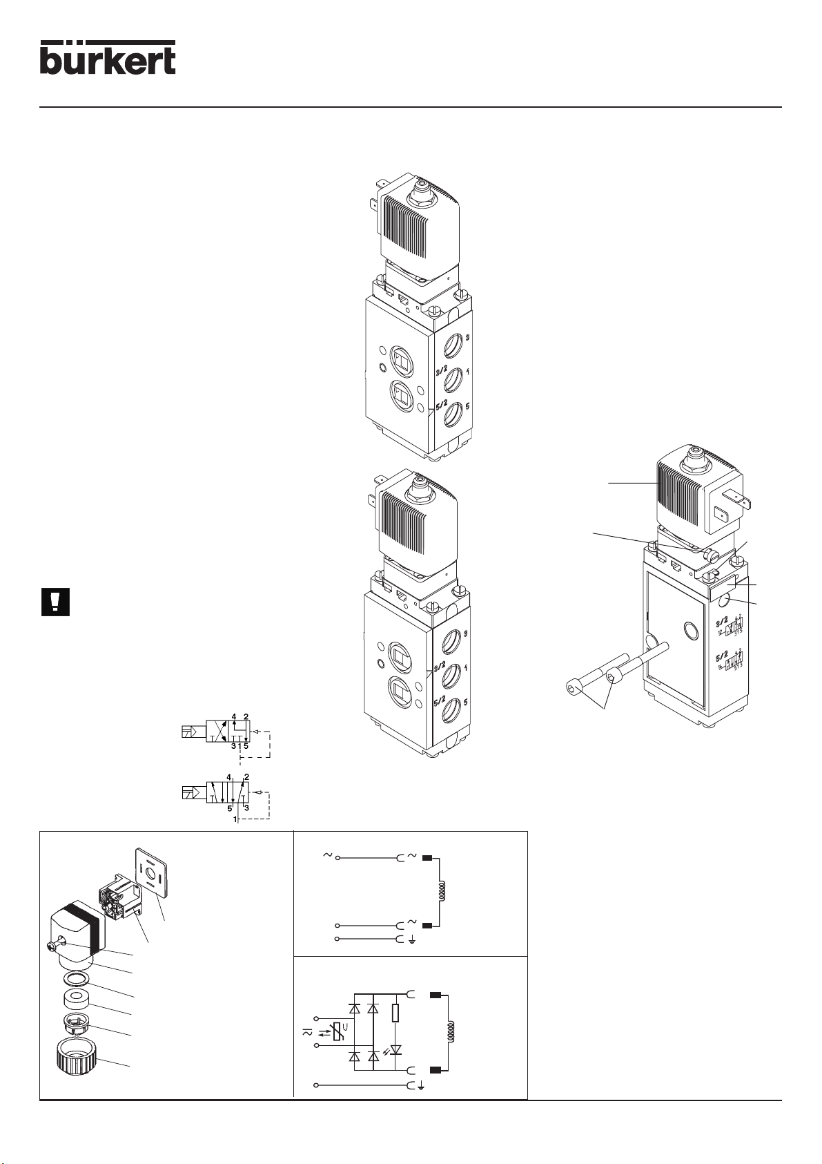
Wirkungsweisen des Ventils 475
3/2-Wege-Ventil, in Ruhestel-
lung Druckanschluss 1 ge-
sperrt, Ausgang 2 entlüftet.
5/2-Wege-Ventil, in Ruhestel-
lung Druckanschluss 1 mit Aus-
gang 2 verbunden, Ausgang 4
entlüftet.
Anwendung Wahlweise in 5/2 oder 3/2
Ausführung
DerUmbauvon5/2in 3/2oderumgekehrterfolgtdurch
Verwendung der mitgelieferten 5/2 oder 3/2-Platte.
5/2
3/2
Bei Verwendung in 3/2 Wege wird 3, mit den
mitgelieferten Verschlusstopfen G1/4, geschlossen.
Bei Verwendung eines 3/2 Wege Ventils 6517 auf
große Antriebe mit schneller Auslasszeit ersetzen Sie
die Verschlusstopfen des Anschlusses 3 mit einem
Schalldämpfer.
Befestigung Ventil / Handbetätigung /
Pneumatische Stellungsanzeige
Das Ventil wird direkt an den pneumatischen Antrieb,
mittels 2 mitgelieferten M5x35 Schrauben, befestigt.
yPilotventil
xHandbetätigung
cAnzeigestift zur pneumatischen Stellungsanzeige.
BeiungeschaltetemVentillässtsichderroteAnzeigestift
eindrücken. Wird das Ventil geschaltet, fährt der
Anzeigestift aus und bleibt in dieser Stellung. Bei jeder
Funktionsüberprüfung muss der Anzeigestift erneut
eingedrückt werden.
vKennzeichnungsschild: abnehmbar für mögliche
Markierungen/ Beschriftungen.
bAnschluss 14:
-in Standardausführungen nicht belegt:
-dient als Steuerhilfsluftanschluss und als Anschluss
für pneumatische Ansteuerungen.
nM5x35-Schrauben
zur Wandmontage des Einzelventils.
Vorsicht: Ventilkörper nicht verspannen!
6517/6519
+
1
2-
(+)
(-) (-)
(+)
1
2
3/2
5/2
NBR flache Dichtung
Kontakteinsatz
Kappe
Zylinderschraube (M3x30)
Druckring
Dichtring
Spannzange
Überwurfmutter
1
2
6
3
4
5
Mit Gleichrichter, LED und Varistor, zum Schutz der LED
vor Spannungspitzen.
Bei Betrieb mit
Gleichspannung
auf richtige
Polung
achten!
Standard
Fluid Control Systems

Pneumatic Valve
Before installation
Check connections, voltage and operating pressures.
Donotexceedmax.operating data(asspecifiedonthe
typelabel).Do notconfuseportconnection 1withports
3 or 5. The manual override must be unlocked for
electrical operation.
Fault-finding
*Pressure differential between the port connections 1
and 3/5 too low, because of too small or contaminated
silencers.
*Insufficientcrosssectionareaofpressuresupply(port
connection 1).
*Internal tube diameter for ports 1/3/5 must be at least
6 mm, in order to ensure a reliable operation of the
valve.
*Locked manual override.
*Exhaustportsofpilot control mechanisms(1/8)onthe
connection modules must not be closed.
Caution: Donotremoveanypipesorvalvesaslongas
the system is pressurized.
Application Guidelines
Carefullyreadtheinstallationandoperatinginstructions.
Attentionmustbepaidtotheapplicationconditionsand
the technical data as specified in the data sheet.
Complying with these instructions will ensure perfect
operation and a long service life.
Application and operation of the device must ensue
according to the general terms of technology.
Appropriate measures must be taken to avoid
unintended operation or unapproved impairment.
Valve Design
* Actuators : - Solenoid operator
- Pneumatic operator
* Valve body with diaphragm and poppet seals (5/2)
* Port connections 2 (B) / 4 (A) with Namur flange
pattern and inlet and outlet ports 1 (P)/3 (R)/5 (S) with
G1/4 internal thread.
Fluid
Filtered compressed air, lubricated or unlubricated.
Seal materials :
BP=PerbunaneandPolyurethanefor3/2and5/2valves.
The external pilot pressure is independent of fluid
pressure and actuator type : it must not exceed 8 bar.
Warning !
Attentionmustbepaidtothemax.permissiblepressure
range as specified on the product label. The pressure
differentialbetweenports1 and 3/5mustbe min. 2bar.
Fluid temperature : max. +50 °C
Ambient temperature : max. +55 °C
Installation
The valve can be installed in any desired position,
preferably with solenoid system upright.
Electrical Connection
Attention must be paid to voltage and current type as
specified on the solenoid operator label. Voltage
tolerance ±10 %. Connection with BÜRKERT-cable
plug 2508 (DIN43650), IP65 rating.
If the DIN43650 cable plug is mounted with
thescrewshowingupwards,insertagasket
under the screw head, whose material is
chemically compatible with your process.
Maintenance
Innormalconditions, thevalvegives maintenance-free
operation.
Circuit functions for the valve 475
3/2-valve. In the off position,
pressure port 1 is closed and
outlet 2 is vented.
5/2-valve. In the off position,
pressure port 1 is linked to
outlet 2 and outlet 4 is vented.
Optional Application in 5/2 or 3/2
Configuration
Thevalvecanbeused in either 5/2or3/2configuration
by using the corresponding 5/2 or 3/2 plate (both
supplied).
5/2
3/2
When used in 3/2 configuration, 3 is blanked off, using
the G1/4 blanking plug supplied.
When using a 6517 valve in 3/2 mode on big actuators
with a fast exhaust time, replace the blanking plug on
the port 3 by a silencer.
Installation for Valve / Manual Override /
Pneumatic Position Indication
The valve is attached directly to the pneumatic drive
mechanism, using the two M5 x 35 bolts supplied.
yPilot valve
xManual override
cPressureindicator forpneumaticpositionindication.
The red indication pin can be pushed in as long as the
valve is not pressurized. When pressurized, the
indicationpinispushedoutandremainsinthisposition.
The pin has to be pushed in for each function
examination.
vSpecification tag (removable for the addition of
markings/specifications)
bPort 14 :
- Not used in the Standard Version
- Used as back-up control air port and as connection
port for pneumatic control.
nM5x35 bolts :
For single valve wall mounting.
Caution : Do not twist valve body !
Without wiring (standard)
With LED and varistor, to protect the LED in case of
voltage transients.
In case of DC-
voltage,
ensure correct
polarity
+
1
2-
(+)
(-) (-)
(+)
1
2
3/2
5/2
6517/6519
Gasket (NBR)
Contact inserts
Lid
Cylindric screw (M3x30)
Pressure ring
Seal ring
Spanner
Union nut
1
2
6
3
4
5
Fluid Control Systems

Vanne pneumatique
Avant la mise en service
Vérifier les raccordements, la tension et la pression de
service. Ne pas dépasser les valeurs de service
maximales (voir plaque signalétique).
Ne pas intervertir le raccordement 1 avec le
raccordement 3 ou 5.
Lacommandemanuelledoitêtredéverrouilléeenmode
de fonctionnement électrique.
Dépannage
* Différence de pression trop faible entre les
raccordements 1 et 3/5 en raison d'un silencieux trop
petit ou encrassé.
*Lediamètreintérieurduflexiblepourlesraccordements
1/3/5 doit être de 6 mm minimum, afin de garantir une
commutation sans problèmes de la vanne.
* Commande manuelle non déverrouillée.
* L'échappement du pilote (G1/8) sur le dessus ne doit
pas être bouché.
Attention:Nedébrancheraucunecanalisationlorsque
le système est sous pression.
Conformité d'utilisation
L'utilisateur doit respecter ces instructions de service
ainsi que les conditions de service et les valeurs
maximales indiquées dans les caractéristiques
techniques afin d'assurer un fonctionnement parfait et
une longue durée de vie de la vanne.
Laplanificationet l'exploitation del'appareildoivent se
faireenconformitéaveclesrèglesdelatechnique.Des
mesures appropriées serviront à empêcher tout
actionnement ou préjudice intempestif.
Constitution de la vanne
* Actionnement : - électro-aimant
- commande pneumatique
* Corps avec membrane et joints de siège (5/2)
* Raccordements de service 2 (B) / 4 (A) selon plan de
pose Namur et raccordements d'alimentation et
d'échappement 1 (P)/3 (R)/5 (S) avec taraudage G1/4.
Fluide
Air comprimé fltré, lubrifié ou non.
Matériau des joints :
BP= Perbunan et polyuréthane pour vannes 3/2 et 5/2.
En cas de commande pneumatique, la pression de
commande est indépendante de la pression du fluide
circulantetdutypedecommande:elledoitêtrede8bar
maximum.
Attention !
Tenir compte de la plage de pression admissible
indiquée sur la plaque signalétique. Différence de
pression minimale de 2 bar entre les raccordements 1
et 3/5.
Température du fluide : max. + 50 °C.
Température ambiante : max. + 55 °C
Montage
Position de montage quelconque ; il est recommandé
de placer le système magnétique vers le haut.
Raccordement électrique
Tenircomptedutype detensionetde courantindiqués
surlaplaquesignalétique.Tolérancedetension±10%.
Raccordement avec connecteur BÜRKERT type 2508
(DIN 43650), indice de protection IP65.
Si le connecteur DIN43650 est monté vis
vers le haut, insérer sous la tête de la vis,
unjointdont lematériauest chimiquement
compatible avec votre process.
Entretien
L'appareil fonctionne sans entretien sous conditions
normales.
Mode de fonctionnement de la vanne 475
Vanne 3/2, au repos,
orifice d'alimentation 1 fermé,
sortie 2 à l'échappement.
Vanne 5/2, au repos,
orifice d'alimentation 1 relié
à la sortie 2, sortie 4 à
l'échappement.
Utilisable en mode 5/2 ou 3/2
Il suffit d'utiliser soit la plaque 5/2 soit la plaque
3/2 fournie.
5/2
3/2
En cas de fonctionnement à 3/2 voies, l'orifice 3 est
fermé avec le bouchon G1/4 fourni avec l'appareil.
encasd'utilisationd'uneélectrovanne6517enmode3/
2 sur de gros actionneurs à chappement rapide, il faut
remplacer le bouchon de l'orifice 3 par un silencieux.
Fixation vanne / commande manuelle /
indicateur de position pneumatique
La vanne est fixée directement sur la commande
pneumatique à l'aide des 2 vis M5x35 fournies avec
l'appareil.
yVanne pilote
xCommande manuelle
cTémoin de pression pour indication pneumatique
de la position. La tige rouge peut être enfoncée si la
vanne n'est pas commutée. Lorsque la vanne est
commutée,la tigedesignalisationressortetrestedans
cetteposition.Latigedesignalisationdoitêtreenfoncée
à chaque test de fonctionnement.
vPlaque signalétique : amovible pour d'éventuels
marquages ou inscriptions.
bRaccordement 14 :
- non affecté en exécution standard :
-sert de raccordement auxiliaire pour l'air comprimé de
commande et de raccordement pour pilotage
pneumatique.
nVis M5X35
pour la fixation murale de la vanne.
Attention : éviter de
déformer le corps
de vanne !
+
1
2-
(+)
(-) (-)
(+)
1
2
3/2
5/2
6517/6519
Joint plat NBR
Inserts de contact
Capot
Vis cylindrique (M3x30)
Rondelle de pression
Bague d'étanchéité
Pince de serrage
Ecrou d'accouplement
1
2
6
3
4
5
Avec redresseur , LED et varistor, pour protection en cas
de pointe de tension!
Vérifier la
polarité pour
utilisation en
courant
continu!
Standard
Fluid Control Systems

Beratung und Service / Advice and service
Conseil et service après-vente
Technische Änderungen vorbehalten / Technical changes without notice / Sous réserve de modifications techniques 00420829_Jun03_B
Fluid Control Systems
Finland
Bürkert Oy
Atomitie 5
SF-00370 Helsinki
Tel +358 (9) 549 706 00
Fax +358 (9) 503 12 75
France
Bürkert Contromatic
B.P. 21
Triembach au Val
F-67220 Villé
Tel +33 (0) 388 58 91 11
Fax +33 (0) 388 57 09 61
Germany / Deutschland
Bürkert Steuer- und Regeltechnik
Christian-Bürkert-Straße 13-17
D-74653 Ingelfingen
Tel +49 7940 10-0
Fax +49 7940 10 361
Niederlassung NRW
Holzener Straβe 70
D-58708 Menden
Tel +49 2373 96 81-0
Fax +49 2373 96 81-52
Niederlassung Frankfurt
Am Flugplatz 27
D-63329 Egelsbach
Tel +49 6103 94 14-0
Fax +49 6103 94 14-66
Niederlassung München
Paul-Gerhardt-Allee 24
D-81245 München
Tel +49 89 82 92 28-0
Fax +49 89 82 92 28-50
Niederlassung Berlin
Bruno-Taut-Straβe 4
D-12524 Berlin
Tel +49 30 67 97 17-0
Fax +49 30 67 97 17-66
Niederlassung Dresden
Christian Bürkert Straße 2
D-01900 Großröhrsdorf
Tel +49 35952 3 63 00
Fax +49 35952 3 65 51
Niederlassung Hannover
Rendsburger Straße 12
D-30569 Hannover
Tel +49 511 9 02 76-0
Fax +49 511 9 02 76-66
Niederlassung Stuttgart
Karl-Benz-Straße 19
D-70794 Filderstadt (Bernh.)
Tel +49 711 4 51 10-0
Fax +49 711 4 51 10-66
Great Britain
Bürkert Contromatic Ltd.
Brimscombe Port Business Park
Brimscombe, Stroud, Glos.
GL5 2QF
Tel. +44 (1453) 73 13 53
Fax +44 (1453) 73 13 43
Hong Kong
Burkert Contromatic
(China/HK) Ltd.
Unit 708, Prosperity Centre
77-81 Container Port Road
Kwai Chung N.T.
Hong Kong
Tel +85 (2) 248 012 02
Fax +85 (2) 241 819 45
Ireland
Bürkert Contromatic Ltd.
Penrose Wharf centre
Penrose Wharf
IRE-Cork
Tel +353 (21) 486 13 36
Fax +353 (21) 733 23 65
Australia
Burkert Fluid Control Systems
Unit 1 No.2, Welder Road
Seven Hills NSW 2147
Tel +61 (2) 983 948 00
Fax +61 (2) 967 461 67
Austria
Bürkert Contromatic GmbH
Central and Eastern Europe
Diefenbachgasse 1-3
A-1150 Wien
Tel +43 (1) 894 13 33
Fax +43 (1) 894 13 00
Belgium
Bürkert Contromatic N.V/S.A
Bijkoevelaan 3
B-2110 Wijnegem
Tel +32 (3) 325 89 00,
Fax +32 (3) 325 61 61
Brazil
Bürkert Contromatic Brasil Ltda
Rua Américo Brasilense 2171, cj 1007
04715-005 Sao Paulo/SP/Brasil
Tel +55 11 5182 0011,
Fax +55 11 5182 8899
Canada
Bürkert Contromatic Inc.
760 Pacific Road, Unit 3
Oakville, Ontario, L6L 6M5
Tel +1 905 847 55 66,
Fax +1 905 847 90 06
China
Bürkert Contromatic
(Suzhou) Co. Ltd.
9-2, Zhu Yuan Road
New District, Suzhou
Jiangsu, 215011 P.R.C
Tel +86 (512) 6808 19 16
Fax +86 (512) 6824 51 06
Bürkert Contromatic
China/HK Ltd.
Rm. 1313
No. 103, Cao Bao Road
Shanghai 200233 P.R.C
Tel +86 (21) 6427 1946
Fax +86 (21) 6427 1945
Bürkert Contromatic
China/HK Ltd.
Beijing Office
Rm. 808, Jing Tai Building
No. 24, Jianguomen
Waidajie
Beijing 100022 P.R.C
Tel +86 (10) 65 15 65 08
Fax +86 (10) 65 15 65 07
Bürkert Contromatic
China/HK Ltd.
Cheng Du Representative Office
Rm. 502, Fuji Building
No. 26 Shududadao
Dongfeng Street
Chengdu P.R.C
Tel +86 (28) 443 1895
Fax +86 (28) 445 1341
Bürkert Contromatic
China/HK Ltd.
Guangzhou Representative Office
Rm. 1305, Tower 2
Dong-Jun Plaza, 828-836
Dongfeng, Road East
Guangzhou P.R.C
Tel +86 20 87 60 58 02
Fax +86 20 87 60 49 79
Denmark
Bürkert-Contromatic A/S
Hørkær 24
DK-2730 Herlev
Tel +45 (44) 50 75 00
Fax +45 (44) 50 75 75
Italy
Bürkert Contromatic Italiana
S.p.A.
Centro Direzionale 'Colombirolo'
Via Roma 74
I-20060 Cassina De' Pecchi (MI)
Tel +39 (02) 959 071
Fax +39 (02) 959 07 251
Japan
Bürkert Contromatic Ltd.
1-8-5 Asagaya Minami
Suginami-ku
Tokyo 166-0004
Tel +81 (3) 5305 3610
Fax +81 (3) 5305 3611
Korea
Bürkert Contromatic Korea Co.
Ltd.
287-2, Doksan 4 Dong
Kumcheon-Ku
Seoul 153-811
Tel. +82 (2) 346 255 92
Fax +82 (2) 346 255 94
Malaysia
Bürkert Contromatic Singapore
Pte. Ltd.
Representative Office
c/o TBP 222, Jalan Baru
137000 Perai, Penang
Tel. +60 (4) 398 2410
Fax +60 (4) 398 2182
Netherlands
Bürkert Contromatic BV
Postbus 1248
NL-3600 BE Maarssen
Tel. +31 346 58 10 10
Fax +31 346 56 37 17
New Zealand
Burkert Contromatic Ltd.
2A, Unit L, Edinburg St
Penrose
Auckland
Tel +64 (9) 622 28 40
Fax +64 (9) 622 28 47
Norway
Bürkert Contromatic A/S
Hvamstubben 17
Box 243
N-2026 Skjetten
Tel +47 (63) 84 62 10
Fax +47 (63) 84 44 55
Philippines
Bürkert Contromatic Inc.
8467, West Service Rd Km 14
South Superhighway, Sunvalley
Paranaque City, Metro Manila
Tel +63 (2) 776 43 84
Fax +63 (2) 776 43 82
Poland
Bürkert Contromatic Sp.z.o.o.
Bernardynska street
PL-02-904 Warszawa
Tel +48 22 840 60 10
Fax +48 22 840 60 11
Singapore
Burkert Contromatic Singapore
Pte.Ltd.
No.11 Playfair Road
Singapore 367986
Tel +65 383 26 12
Fax +65 383 26 11
Spain
Bürkert Contromatic S.A.
Avda. Barcelona, 40
E-08970 Sant Joan Despi,
Barcelona
Tel +34 (93) 477 79 80
Fax +34 (93) 477 79 81
South Africa
Burkert Contromatic Pty.Ltd.
P.O.Box 26260, East Rand 1462
Republic of South Africa
Tel +27 (11) 397 2900
Fax +27 (11) 397 4428
Sweden
Bürkert Contromatic AB
Skeppsbron 13 B
S-21120 Malmö
Tel +46 (40) 664 51 00
Fax +46 (40) 664 51 01
Bürkert Contromatic AB
Havsörnstorget 21
Box 1002
S-12349 Farsta
Tel +46 (8) 724 01 27
Fax +46 (8) 724 60 22
Switzerland
Bürkert-Contromatic AG International
Bösch 71, P.O. Box
CH-6331 Hünenberg / ZG
Tel +41 41 785 66 66
Fax +41 41 785 66 33
Taiwan
Bürkert Contromatic Taiwan Ltd.
3F No. 475 Kuang-Fu South Road
R.O.C - Taipei City
Tel +886 (0) 2 275 831 99
Fax +886 (0) 2 275 824 99
Turkey
Bürkert Contromatik
Akiskan Kontrol Sistemleri Ticaret A.S
1203/8 Sok. No. 2-E
Yenisehir
Izmir
Tel +90 (232) 459 53 95
Fax +90 (232) 459 76 94
Tzechia
Bürkert Contromatic Spol.s.r.o
Prosenice c. 180
CZ - 751 21 Prosenice
Tel +42 0641 226 180
Fax +42 0641 226 181
USA/West/Main office
Burkert Contromatic Corp.
2602 McGaw Avenue
Irvine, CA 92614, USA
Tel. +1 (949) 223 31 00
Fax +1 (949) 223 31 98
This manual suits for next models
1
Table of contents
Languages:
Other Burkert Control Unit manuals

Burkert
Burkert 6511 User manual

Burkert
Burkert 770 User manual

Burkert
Burkert 2031 User manual

Burkert
Burkert 6144 User manual

Burkert
Burkert 6518 User manual

Burkert
Burkert 2100 series Guide

Burkert
Burkert Type 2000 User manual

Burkert
Burkert 2301 Series User manual

Burkert
Burkert 0470 User manual

Burkert
Burkert AirLINE 8652 User manual

Burkert
Burkert 0127 User manual

Burkert
Burkert 2100 series User manual

Burkert
Burkert 2031 User manual

Burkert
Burkert 8691 User manual

Burkert
Burkert 0262 User manual

Burkert
Burkert 6011 User manual

Burkert
Burkert 2106 User manual

Burkert
Burkert 5281 EV User manual

Burkert
Burkert 2060 User manual

Burkert
Burkert 6518 User manual