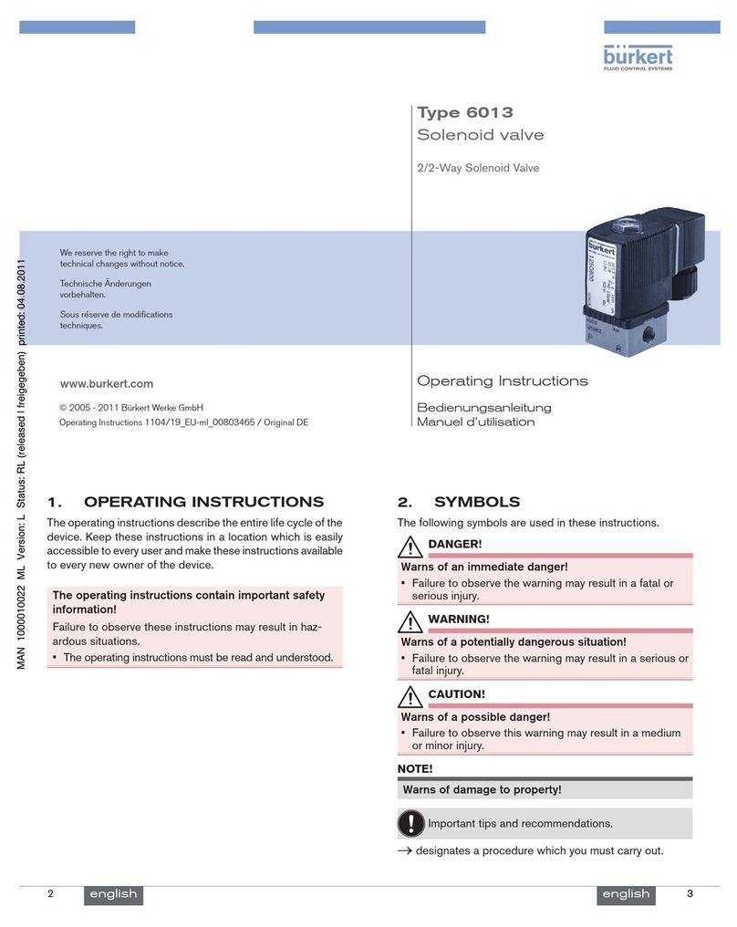
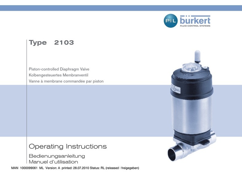
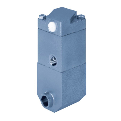
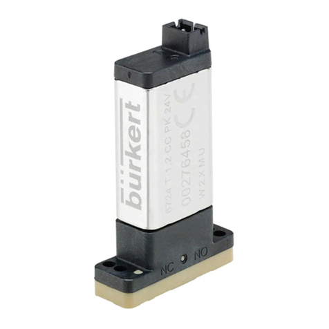
Burkert 2060 User manual

Quickstart
English Deutsch Français
Type 2060
INOX
2/2-way angle seat valve
2/2-Wege Schrägsitzventil
Vanne à siège incliné 2/2 voies

2
Quickstart
Type 2060 INOX
1 QUICKSTART ........................................................................ 2
2 CONTACT ADDRESSES ....................................................... 2
3 INTENDED USE .................................................................... 3
4 BASIC SAFETY INSTRUCTIONS.......................................... 3
5 TECHNICAL DATA................................................................. 4
6 INSTALLATION ...................................................................... 6
7 START-UP.............................................................................. 8
8 MAINTENANCE, CLEANING ................................................ 8
9 DISASSEMBLY...................................................................... 9
10 TRANSPORTATION, STORAGE, DISPOSAL........................ 9
1 QUICKSTART
The Quickstart contains important information.
▶Carefully read the Quickstart and follow the safety instructions.
▶The Quickstart must be available to each user.
▶The liability and warranty for the Type2060 INOX will be invali-
dated if the Quickstart instructions are not followed.
The Quickstart provides an exemplary description of the installation
and start-up of the device. The detailed description of the device can
be found in the operating instructions for Type2060 INOX online at:
country.burkert.com
2 CONTACT ADDRESSES
Bürkert Fluid Control Systems/Sales Center
Christian-Bürkert-Str.13–17
D-74653 Ingelngen, Germany
Tel. +49(0)7940-1091111/Fax +49(0)7940-1091448
E-mail: [email protected]
International
You can nd the international contact addresses on the Internet
at: www.burkert.com
Contact the Bürkert sales department with any questions.
Contents
We reserve the right to make technical changes without notice.
Technische Änderungen vorbehalten.
Sous réserve de modications techniques.
©Bürkert WerkeGmbH&Co.KG, 2020
Operating Instructions 2009/00_EU-ML_00815368/Original DE
English

3
Quickstart
Type 2060 INOX
2.1 Symbols
Warns of fatal or serious injuries:
DANGER!
Warns of an immediate danger!
WARNING!
Warns of a potentially hazardous situation!
Warns of moderate or minor injuries:
CAUTION!
Warns of a potential danger!
NOTE!
Warns of damage!
Important tips and recommendations.
→Designates a procedure which you must carry out.
3 INTENDED USE
The Type2060 INOX angle seat valve is designed to control the
ow of liquid and gaseous media.
•To use the device, observe the permitted application conditions.
•Only use the device when it is in perfect condition; always ensure
proper storage, transportation, installation and operation.
•In potentially explosive environments, the device must only be
used in accordance with the specications on the separate
Ex-type label. The additional information and safety instructions
relating to Ex areas enclosed with the device must be adhered
to when deploying the device.
•Devices without a separate Ex type label must not be used in the
potentially explosive atmosphere.
•Use the device only in conjunction with third-party devices and
components recommended or approved by Bürkert.
•Only use the device as intended.
4 BASIC SAFETY INSTRUCTIONS
Danger from high pressure.
▶Before loosening lines or valves, switch o the pressure and
bleed/drain the lines.
Danger due to electrical voltage.
▶Before reaching into the device or the system, switch o the
power supply and secure to prevent reactivation!
▶Observe the applicable accident prevention and safety regu-
lations for electrical devices!
Risk of crushing due to moving pneumatic port.
▶Do not touch the moving pneumatic port when opening and
closing the device.
▶Do not reach into the area directly above and below the pilot
air port.
Risk of pressure surge ow with ow direction above the seat.
▶Because of the risk of pressure surge, angle seat valves with the
ow direction above the seat must not be used for uid media.
English

4
Quickstart
Type 2060 INOX
Risk of burns/re due to hot device surface if device operated
continuously!
▶Do not touch the device with your bare hands.
▶Keep the device away from highly ammable substances and
media.
Ensure the following the prevent injuries:
▶Secure the system/device against unintentional activation.
▶Feed only those media, which are listed in the chapter "Tech-
nical data" as ow media, into the medium ports.
▶Do not make any internal or external changes to the Type2060
INOX device.
▶Only trained technicians carry out installation and mainte-
nance work.
▶Following an interruption in the power supply, ensure that
the process is restarted in a controlled manner.
▶Do not use in areas susceptible to vibrations.
▶Do not mechanically load the device.
▶Observe general engineering standards and rules.
5 TECHNICAL DATA
5.1 Conformity
The angle seat valve Type2060 INOX conforms to the EU directives
as per the EUDeclaration of Conformity.
5.2 Standards
The applied standards as used to verify compliance with the
EUDirectives can be found in the EUtype examination certicate
and/or the EUDeclaration of Conformity.
5.3 General technical data
Control functions: A (CFA)/B (CFB)
CFA: Closed by spring force in rest position.
CFB: Opened by spring force in rest position.
For materials and ports: see data sheet
Installation position: any, preferably actuator facing up
5.4 Inscription on the type label
Flow direction
Seal material
Flow
coecient
Control function (CF)
Type
Permitted ambient temperature
For derating, please refer to the
operating instructions,
Identication number of device
Manufacture code
CE marking (if applicable)
Permissible medium pressure, permissible
pilot pressure
English

5
Quickstart
Type 2060 INOX
5.5 Operating conditions
5.5.1 Permitted temperatures
Ambient temperature: 0°C...+60°C
Medium temperature: 0°C...+200°C
The angle seat valve is autoclavable.
The pilot air port must be removed for this.
Derating pressure and temperature ranges
Usage limits of the armature (derating medium pressure)
Temperature Medium pressure
150°C 14.8bar
200°C 13.7bar
Tab. 1: Derating the medium pressure as per ASMEB16.5/
ASMEB16.34Cl.150
Temperature Medium pressure
–10...+50 °C 14bar
100°C 14bar
150°C 13.4bar
200°C 12.4bar
Tab. 2: Derating the medium pressure as per JISB222010K
0 20 40 60 80 100 120 140 160 180 200
50
60
140
130
120
110
100
90
80
70
Ambient temperature [°C]
Medium temperature [°C]
Fig. 1: Derating VA actuator INOX ANTG32
5.5.2 Pressure ranges
WARNING!
Risk of medium leak and bursting.
Exceeding the permissible medium or pilot pressure can
cause a leak and bursting of the lines or device. With control
functionB, too little pilot pressure can cause a leak.
▶Do not exceed the medium pressure and pilot pressure.
▶With control function B, adhere to the minimum pilot pres-
sure of 4bar.
The following product-specic pressure information is provided
on the type label. Pilot pressure for control functionB: 4bar
English

6
Installation
Type 2060 INOX
5.5.3 Media
WARNING!
Risk of injury due to burst lines caused by a pressure surge.
If the valve with ow direction above the seat is used for liquid
media, a pressure surge can cause the lines and device to
burst.
▶Do not use valves with ow direction above the seat for
liquid media.
Control medium: neutral gases, air
Flow media: Water, alcohols, oils, fuels, hydraulic uids, saline
solutions, lyes, organic solvents, vapour, air, neutral gases.
6 INSTALLATION
DANGER!
Risk of injury from high pressure in the system.
▶Before loosening lines or valves, switch o the pressure and
bleed/drain the lines.
WARNING!
Risk of injury due to improper installation!
▶Installation may be carried out by authorised technicians
only and with the appropriate tools!
Risk of injury due to unintentional activation of the system
and uncontrolled restart!
▶Secure the system against unintentional activation.
▶Following installation, ensure a controlled restart.
Risk of crushing due to moving pneumatic port!
▶Do not touch the moving pneumatic port when opening and
closing the device.
▶Do not reach into the area directly above and below the pilot
air port.
6.1 Preparatory work
→Ensure that (de-energized) pipelines are aligned before con-
necting the valve.
→Clear impurities from pipelines (seal material, metal chips,
etc.).
Devices with welded connection:
Remove the actuator from the valve body:
English

7
Installation
Type 2060 INOX
→Clamp valve body into a collet.
NOTE!
Damage to the seat seal or seat contour!
→With control functionA, open valve: Pressurize lower pilot
air port with compressed air (5bar).
→Place a suitable open-end wrench on the wrench at of the
nipple.
→Unscrew actuator from the valve body.
Devices with socket connection:
→Only uninstall the actuator if required by the customer.
6.2 Installation
6.2.1 Install valve body into pipeline
For welded connections:
→Weld or bond valve body in pipeline system.
→Check graphite seal and replace if required.
Graphite seal
For other device variants:
→Connect valve body to pipeline.
6.2.2 Installing actuator on valve body
DANGER!
Risk of explosion due to incorrect lubricants!
Unsuitable lubricant may contaminate the medium. There is a
risk of explosion in oxygen applications.
▶For specic applications, e.g. oxygen or analysis applica-
tions, use approved lubricants only.
WARNING!
Risk of injury due to damaged devices!
Using the wrong tool and too much tightening torque can
damage the device during installation.
▶Use an open-end wrench when installing the actuator, never
a pipe wrench.
▶Observe the tightening torque (40±3Nm)
→Before re-installation, grease the pipe thread of the actuator
(e.g. using Klüberpaste UH196-402 from Klüber).
→For control functionA: Apply compressed air to the pilot air
port (5.5bar) so that the swivel plate lifts up from the valve seat
and is not damaged during the screw-in process.
→Screw actuator into the valve body.
Observe the tightening torque (40±3Nm)!
English

8
Start-up
Type 2060 INOX
6.3 Pneumatic connection
WARNING!
Risk of injury due to unsuitable connection hoses!
Hoses that cannot withstand the pressure and temperature
range can cause hazardous situations.
▶Only use hoses that are permitted for the specied pressure
and temperature range.
▶Note the data sheet information from the hose
manufacturers.
6.3.1 Pilot air ports
The 45° elbow connection, available separately, is
recommended as a pilot air port!
The free-moving hose length for this should be
at least 250mm. A shorter hose length reduces
the durability and function of the plug-in coupling!
Order no.903383
When using a straight pilot air port, the free-
moving hose length should be at least 400mm.
A shorter hose length reduces the durability and
function of the plug-in coupling!
Risk of crushing!
▶Because of the risk of crushing, a
90° pilot air port must not be used!
7 START-UP
WARNING!
Risk of injury due to improper operation!
▶Before start-up, ensure that the operating personnel are
aware of and have completely understood the contents of
the operating instructions.
▶The safety instructions and the intended use must be
observed.
▶Only adequately trained personnel may start up the system/
device.
Observe the type label information as well as the pressure
and temperature values in chapter “5 Technical data”.
8 MAINTENANCE, CLEANING
→Perform a visual inspection of the device once per year. Shorter
maintenance intervals are recommended depending on the
usage conditions.
Wearing parts: Swivel plate and graphite seal.
→If leaks occur, replace the respective wearing part.
For a description, refer to the main instructions online.
8.1 Cleaning
Commercially available cleaning agents can be used to clean the
device surface.
NOTE!
Before cleaning, check that the cleaning agents are compatible
with body materials and seals.
English

9
Disassembly
Type 2060 INOX
9 DISASSEMBLY
DANGER!
Risk of injury from discharge of pressure and escaping medium!
Dismantling a device which is under pressure is hazardous due to
a sudden discharge of pressure or escaping medium.
▶Before cleaning, shut o the pressure and vent all lines.
Procedure:
→Disconnect the pneumatic connection.
→Disassemble the device.
10 TRANSPORTATION, STORAGE,
DISPOSAL
NOTE!
Damage from transport and storage!
•Protect the device against moisture and dirt in shock-
resistant packaging during transportation and storage.
•Permitted storage temperature: –20...+65°C.
Damage to the environment caused by device parts con-
taminated with media.
•Dispose of the device and packaging in an environmentally
friendly manner!
English

10
Der Quickstart
Typ 2060 INOX
1 DER QUICKSTART.............................................................. 10
2 KONTAKTADRESSEN ......................................................... 10
3 BESTIMMUNGSGEMÄSSER GEBRAUCH......................... 11
4 GRUNDLEGENDE SICHERHEITSHINWEISE..................... 11
5 TECHNISCHE DATEN ......................................................... 12
6 MONTAGE ........................................................................... 15
7 INBETRIEBNAHME............................................................. 17
8 WARTUNG, REINIGUNG .................................................... 17
9 DEMONTAGE ...................................................................... 17
10 TRANSPORT LAGERUNG, ENTSORGUNG....................... 17
1 DER QUICKSTART
Der Quickstart enthält wichtige Informationen.
▶Quickstart sorgfältig lesen und Hinweise zur Sicherheit
beachten.
▶Quickstart muss jedem Benutzer zur Verfügung stehen.
▶Die Haftung und Gewährleistung für Typ 2060 INOX entfällt,
wenn die Anweisungen des Quickstarts nicht beachtet werden.
Der Quickstart erläutert beispielhaft die Montage und Inbetriebnahme
des Geräts. Die ausführliche Beschreibung des Geräts nden Sie in
der Bedienungsanleitung für den Typ 2060 INOX im Internet unter:
country.burkert.com
2 KONTAKTADRESSEN
Bürkert Fluid Control Systems / Sales Center
Christian-Bürkert-Str. 13-17
D-74653 Ingelngen
Tel. + 49 (0) 7940 - 10 91 111 / Fax + 49 (0) 7940 - 10 91 448
E-mail: [email protected]
International
Die Kontaktadressen nden Sie im Internet unter:
www.burkert.com
Bei Fragen Ihre Bürkert-Vertriebsniederlassung kontaktieren.
InhaltsverzeIChnIs
deutsch

11
Der Quickstart
Typ 2060 INOX
2.1 Darstellungsmittel
Warnung vor tödlichen oder schweren Verletzungen:
GEFAHR!
Warnt vor einer unmittelbaren Gefahr!
WARNUNG!
Warnt vor einer möglicherweise gefährlichen Situation!
Warnung vor mittelschweren oder leichten Verletzungen:
VORSICHT!
Warnt vor einer möglichen Gefährdung!
HINWEIS!
Warnt vor Sachschäden!
Wichtige Tipps und Empfehlungen.
→markiert einen Arbeitsschritt den Sie ausführen müssen.
3 BESTIMMUNGSGEMÄSSER
GEBRAUCH
Das Schrägsitzventil Typ 2060 INOX ist für die Steuerung des
Durchusses von üssigen und gasförmigen Medien konzipiert.
•Für den Einsatz die zulässigen Einsatzbedingungen beachten.
•Nur in einwandfreiem Zustand betreiben und auf sachgerechte
Lagerung, Transport, Installation und Bedienung achten.
•Im explosionsgefährdeten Bereich darf das Gerät nur entspre-
chend der Spezikation auf dem separaten Ex-Typschild einge-
setzt werden. Für den Einsatz muss die dem Gerät beiliegende
Zusatzinformation mit Sicherheitshinweisen für den Ex-Bereich
beachtet werden.
•Geräte ohne separates Ex-Typschild dürfen nicht im explosions-
gefährdeten Bereich eingesetzt werden.
•Das Gerät nur in Verbindung mit von Bürkert empfohlenen bzw.
zugelassenen Fremdgeräten und -komponenten einsetzen.
•Das Gerät nur bestimmungsgemäß einsetzen.
4 GRUNDLEGENDE
SICHERHEITSHINWEISE
Gefahr durch hohen Druck!
▶Vor dem Lösen von Leitungen oder Ventilen den Druck
abschalten und Leitungen entlüften/entleeren.
Gefahr durch elektrische Spannung!
▶Vor Eingrien in das Gerät oder die Anlage, Spannung
abschalten und vor Wiedereinschalten sichern!
▶Die geltenden Unfallverhütungs- und Sicherheitsbestimmun-
gen für elektrische Geräte beachten!
Quetschgefahr durch sich bewegenden pneumatischen
Anschluss!
▶Beim Önen und Schließen des Gerätes nicht den sich
bewegenden pneumatischen Anschluss berühren.
▶Nicht in den unmittelbaren Bereich oberhalb und unterhalb
des Steuerluftanschlusses fassen.
deutsch

12
Technische Daten
Typ 2060 INOX
▶Schließschlaggefahr bei Anströmung über Sitz!
•Bei Anströmung über Sitz das Schrägsitzventil, wegen Schließ-
schlaggefahr nicht für üssige Medien einsetzen.
Verbrennungsgefahr/Brandgefahr bei Dauerbetrieb durch
heiße Geräteoberäche!
▶Das Gerät nicht mit bloßen Händen berühren.
▶Das Gerät von leicht brennbaren Stoen und Medien
fernhalten.
Zum Schutz vor Verletzungen ist zu beachten:
▶Anlage/Gerät vor unbeabsichtigtem Betätigen sichern.
•In die Medienanschlüsse nur Medien einspeisen, die im Kapitel
„Technische Daten“ als Durchussmedien aufgeführt sind.
▶An Typ 2060 INOX keine inneren oder äußeren Veränderungen
vornehmen.
▶Nur geschultes Fachpersonal darf Installations- und Instand-
haltungsarbeiten ausführen.
▶Nach Unterbrechung der elektrischen Versorgung für einen
kontrollierten Wiederanlauf des Prozesses sorgen.
▶Nicht in schwingungsgefährdeten Bereichen verwenden.
▶Gerät nicht mechanisch belasten.
▶Die allgemeinen Regeln der Technik einhalten.
5 TECHNISCHE DATEN
5.1 Konformität
Das Schrägsitzventil, Typ 2060 INOX ist konform zu den EU-
Richtlinien entsprechend der EU-Konformitätserklärung
5.2 Normen
Die angewandten Normen, mit denen die Konformität zu den EU-
Richtlinien nachgewiesen wird, sind in der EU-Baumusterprüfbe-
scheinigung und/oder der EU-Konformitätserklärung nachzulesen.
5.3 Allgemeine Technische Daten
Steuerfunktionen: A (SFA) / B (SFB)
SFA: In Ruhestellung durch Federkraft geschlossen.
SFB: In Ruhestellung durch Federkraft geönet.
Werkstoe und Anschlüsse: siehe Datenblatt
Einbaulage: beliebig, vorzugsweise Antrieb nach oben
deutsch

13
Technische Daten
Typ 2060 INOX
Beschriftung des Typschilds:
Durchussrichtung
Dichtwerksto
Durchuss-
koezient
Steuerfunktion (SF)
Typ
Zulässige Umgebungstemperatur
Derating siehe Bedienungsanleitung,
Identnummer des Geräts
Herstellcode
CE-Kennzeichnung (wenn anwendbar)
Zulässiger Mediumsdruck, Zulässiger
Steuerdruck
5.4 Betriebsbedingungen
5.4.1 Zulässigen Temperaturen
Umgebungstemperatur: 0 °C…+60 °C
Mediumstemperatur: 0 °C…+200 °C
Das Schrägsitzventil ist autoklavierbar.
Hierzu muss der Steuerluftanschluss entfernt werden.
Derating Druck- und Temperaturbereich
Einsatzgrenzen der Armatur (Derating Mediumsdruck)
Temperatur Mediumsdruck
150 °C 14,8 bar
200 °C 13,7 bar
Tab. 1: Derating des Mediumsdrucks nach ASME B16.5/ ASME B16.34
Cl.150
Temperatur Mediumsdruck
-10...+50 °C 14 bar
100 °C 14 bar
150 °C 13,4 bar
200 °C 12,4 bar
Tab. 2: Derating des Mediumsdrucks nach JIS B 2220 10K
deutsch

14
Technische Daten
Typ 2060 INOX
0 20 40 60 80 100 120 140 160 180 200
50
60
140
130
120
110
100
90
80
70
Umgebungstemperatur [°C]
Mediumstemperatur [°C]
Bild 1: Derating VA-Antrieb INOX ANTG 32
5.4.2 Druckbereiche
WARNUNG!
Mediumsaustritt und Berstgefahr.
Ein Überschreiten des zulässigen Mediums- oder Steuerdrucks
kann zu Undichtigkeit und zum Bersten von Leitungen oder
Gerät führen. Bei Steuerfunktion B kann ein zu geringer Steuer-
druck zu Undichtigkeit führen.
▶Mediumsdruck und Steuerdruck nicht überschreiten.
▶Bei Steuerfunktion B den Mindeststeuerdruck von 4 bar
einhalten.
Die produktspezischen Druckangaben sind auf dem Typschild
angegeben. Mindeststeuerdruck bei Steuerfunktion B: 4 bar
5.4.3 Medien
WARNUNG!
Verletzungsgefahr durch berstende Leitungen infolge eines
Schließschlags!
Wird bei Anströmung über Sitz das Ventil für üssige Medien
eingesetzt, kann ein Schließschlag zum Bersten von Leitungen
und Gerät führen.
▶Ventile mit Anströmung über Sitz nicht für üssige Medien
einsetzen!
Steuermedium: neutrale Gase, Luft
Durchussmedien: Wasser, Alkohole, Öle, Treibstoe, Hydraulik-
üssigkeiten, Salzlösungen, Laugen, organische Lösungsmittel,
Dampf, Luft, neutrale Gase.
deutsch

15
Montage
Typ 2060 INOX
6 MONTAGE
GEFAHR!
Verletzungsgefahr durch hohen Druck in der Anlage.
▶Vor dem Lösen von Leitungen oder Ventilen den Druck
abschalten und Leitungen entlüften/entleeren.
WARNUNG!
Verletzungsgefahr bei unsachgemäßer Montage!
▶Die Montage darf nur autorisiertes Fachpersonal mit geeig-
netem Werkzeug durchführen!
Verletzungsgefahr durch ungewolltes Einschalten der Anlage
und unkontrollierten Wiederanlauf!
▶Anlage vor unbeabsichtigtem Betätigen sichern.
▶Nach der Montage einen kontrollierten Wiederanlauf
gewährleisten.
Quetschgefahr durch sich bewegenden pneumatischen
Anschluss!
▶Beim Önen und Schließen des Gerätes nicht den sich
bewegenden pneumatischen Anschluss berühren.
▶Nicht in den unmittelbaren Bereich oberhalb und unterhalb
des Steuerluftanschlusses fassen.
6.1 Vorbereitende Arbeiten
→Vor dem Anschluss des Ventils auf uchtende (spannungs-
freie) Rohrleitungen achten.
→Rohrleitungen von Verunreinigungen säubern (Dichtungsma-
terial, Metallspäne etc.)
Geräte mit Schweißgehäuse:
Antrieb vom Ventilgehäuse demontieren:
→Ventilgehäuse in eine Haltevorrichtung einspannen.
HINWEIS!
Beschädigung Sitzdichtung bzw. Sitzkontur!
→Bei Steuerfunktion A Ventil önen: Unteren Steuerluftan-
schluss mit Druckluft (5 bar) beaufschlagen.
→An der Schlüsseläche des Nippels mit passendem Gabel-
schlüssel ansetzen.
→Antrieb vom Ventilgehäuse abschrauben.
Geräte mit Muengehäuse:
→Antrieb nur bei kundenspezischem Erfordernis demontieren.
6.2 Einbau
6.2.1 Ventilgehäuse in Rohrleitung einbauen
Bei Schweißgehäusen:
→Ventilgehäuse in Rohrleitungssystem einschweißen.
→Graphitdichtung prüfen und bei Bedarf erneuern.
Graphitdichtung
Bei anderen Gehäuseausführungen:
→Ventilgehäuse mit Rohrleitung verbinden.
deutsch

16
Montage
Typ 2060 INOX
6.2.2 Antrieb auf Ventilgehäuse montieren
GEFAHR!
Explosionsgefahr durch falsche Schmierstoe!
Ungeeigneter Schmiersto kann das Medium verun-
reinigen. Bei Sauerstoanwendungen besteht dadurch
Explosionsgefahr.
▶Bei spezischen Anwendungen wie z. B. Sauersto - oder
Analyseanwendungen nur entsprechend zugelassene
Schmierstoe verwenden.
WARNUNG!
Verletzungsgefahr durch beschädigte Geräte!
Durch falsches Werkzeug und ein zu großes Anziehdreh-
moment kann das Gerät bei der Montage beschädigt werden.
▶Zur Montage des Antriebs einen Gabelschlüssel, keinesfalls
eine Rohrzange verwenden.
▶Anziehdrehmoment beachten (40 ± 3 Nm)
→Rohrgewinde vor Wiedereinbau des Antriebes einfetten
(z. B. mit Klüberpaste UH1 96-402 der Fa. Klüber).
→Bei Steuerfunktion A: Steuerluftanschluss mit Druckluft (5,5 bar)
beaufschlagen, damit der Pendelteller vom Ventilsitz abhebt und
beim Einschrauben nicht beschädigt wird.
→Antrieb in das Ventilgehäuse einschrauben.
Anziehdrehmoment (40 ± 3 Nm) beachten!
6.3 Pneumatischer Anschluss
WARNUNG!
Verletzungsgefahr durch ungeeignete Anschlussschläuche!
Schläuche die dem Druck- und Temperaturbereich nicht stand-
halten, können zu gefährlichen Situationen führen.
▶Nur Schläuche verwenden, die für den angegeben Druck-
und Temperaturbereich zugelassen sind.
▶Die Datenblattangaben der Schlauchhersteller beachten.
6.3.1 Steuerluftanschlüsse
Als Steuerluftanschluss ist der separat bestellbare
45°-Winkelanschluss zu empfehlen!
Hier sollte die freibewegliche Schlauchlänge min.
250 mm betragen. Bei einer kürzeren Schlauch-
länge wird die Haltbarkeit und Funktion der
Steckkupplung beeinträchtigt! Bestell-Nr. 903383
Bei der Verwendung eines geraden Steuerluftan-
schlusses sollte die freibewegliche Schlauchlänge
min. 400 mm betragen.
Bei einer kürzeren Schlauchlänge wird die
Haltbarkeit und Funktion der Steckkupplung
beeinträchtigt!
Quetschgefahr!
▶Aufgrund der Quetschgefahr darf ein
90°-Steuerluftanschluss nicht verwendet
werden!
deutsch

17
Inbetriebnahme
Typ 2060 INOX
7 INBETRIEBNAHME
WARNUNG!
Verletzungsgefahr bei unsachgemäßem Betrieb!
▶Vor der Inbetriebnahme muss gewährleistet sein, dass der
Inhalt der Bedienungsanleitung dem Bedienungspersonal
bekannt ist und vollständig verstanden wurde.
▶Die Sicherheitshinweise und die bestimmungsgemäße Ver-
wendung müssen beachtet werden.
▶Nur ausreichend geschultes Personal darf die Anlage/das
Gerät in Betrieb nehmen.
Typschildangaben und die Hinweise zu Druck- und Tem-
peraturwerten in Kapitel „5 Technische Daten“ beachten.
8 WARTUNG, REINIGUNG
→Sichtkontrolle einmal pro Jahr am Gerät durchführen. Je nach Ein-
satzbedingungen werden kürzere Wartungsintervalle empfohlen.
Verschleißteile: Pendelteller und Graphitdichung.
→Bei Undichtheiten das jeweilige Verschleißteil austauschen.
Beschreibung siehe Hauptanleitung im Internet.
8.1 Reinigung
Zur Reinigung der Geräteoberäche können handelsübliche Rei-
nigungsmittel verwendet werden.
HINWEIS!
Die Verträglichkeit der Mittel mit den Gehäusewerkstoen und
Dichtungen vor der Reinigung prüfen.
9 DEMONTAGE
GEFAHR!
Verletzungsgefahr durch Mediumsaustritt und Druckentladung!
Der Ausbau eines Geräts das unter Druck steht ist wegen plötz-
licher Druckentladung oder Mediumsaustritt gefährlich.
▶Vor dem Ausbau den Druck abschalten und Leitungen
entlüften.
Vorgehensweise:
→Pneumatischer Anschluss lösen.
→Gerät demontieren.
10 TRANSPORT LAGERUNG,
ENTSORGUNG
HINWEIS!
Transportschäden und Lagerschäden!
•Gerät vor Nässe und Schmutz geschützt in einer stoßfesten
Verpackung transportieren und lagern.
•Zulässige Lagertemperatur: –20 … +65 °C.
Umweltschäden durch von Medien kontaminierte Geräteteile.
•Gerät und Verpackung umweltgerecht entsorgen!
deutsch

18
Quickstart
Type 2060 INOX
1 QUICKSTART ...................................................................... 18
2 ADRESSES DE CONTACT .................................................. 18
3 UTILISATION CONFORME ................................................. 19
4 CONSIGNES DE SÉCURITÉ FONDAMENTALES............... 19
5 CARACTÉRISTIQUES TECHNIQUES ................................. 20
6 INSTALLATION .................................................................... 23
7 MISE EN SERVICE.............................................................. 25
8 NETTOYAGE, MAINTENANCE............................................ 25
9 DÉMONTAGE ...................................................................... 25
10 TRANSPORT, STOCKAGE, ÉLIMINATION ......................... 26
1 QUICKSTART
Le Quickstart contient des informations importantes.
▶Lire attentivement le Quickstart et tenir compte des consignes
de sécurité.
▶Le Quickstart doit être mis à disposition de chaque utilisateur.
▶La responsabilité et la garantie légale concernant le type 2060
INOX sont exclues en cas de non-respect des instructions
gurant dans le Quickstart.
Le manuel Quickstart explique à l’aide d’exemples l’installation
et la mise en service de l’appareil. Vous trouverez la description
détaillée de l'appareil dans le manuel d'utilisation du type 2060
INOX sur Internet sous:
country.burkert.com
2 ADRESSES DE CONTACT
Bürkert Fluid Control Systems / Sales Center
Christian-Bürkert-Str. 13-17
D-74653 Ingelngen
Tél. + 49 (0) 7940 - 10 91 111 / Fax + 49 (0) 7940 - 10 91 448
E-mail: [email protected]
International
Vous trouverez les adresses de contact sur le site Internet:
www.burkert.com
En cas de questions, contacter votre distributeur Bürkert.
table des matIères
Français

19
Quickstart
Type 2060 INOX
2.1 Moyens de signalisation
Mise en garde contre des blessures graves, voire mortelles:
DANGER!
Met en garde contre un danger imminent!
AVERTISSEMENT!
Met en garde contre une situation potentiellement
dangereuse!
Mise en garde contre les blessures légères ou moyennement
graves:
ATTENTION!
Met en garde contre un risque potentiel!
REMARQUE!
Met en garde contre les dommages matériels!
Conseils et recommandations importants.
→identie une opération que vous devez eectuer.
3 UTILISATION CONFORME
La vanne à siège incliné de type 2060 INOX a été conçue pour la
commande du débit de uides liquides et gazeux.
•Pour l'utilisation, il convient de respecter les conditions d'utili-
sation autorisées.
•Ne l’exploiter que si elle est en parfait état. Veiller à un stockage,
à un transport, à une installation et à la commande conformes.
•Dans une zone exposée à un risque d'explosion, l’appareil doit
impérativement être installé conformément à la spécication
indiquée sur l’étiquette d'identicationEx. L’information supplé-
mentaire comportant des consignes de sécurité pour zoneEx
fournie avec l’appareil, doit être respectée lors de l’utilisation
de celui-ci.
•Les appareils sans étiquette d'identication Ex séparée ne doivent
pas être utilisés en zone explosible.
•Utiliser uniquement l'appareil en association avec les appareils et
composants étrangers recommandés et homologués par Bürkert.
•L'appareil doit être utilisé uniquement de manière conforme.
4 CONSIGNES DE SÉCURITÉ
FONDAMENTALES
Danger lié à une pression élevée!
▶Avant de desserrer les conduites ou les vannes, couper la
pression et purger/vidanger les conduites.
Danger lié à une tension électrique!
▶Avant d’intervenir dans l’appareil ou l’installation, cou-
per la tension et empêcher toute remise sous tension par
inadvertance!
▶Respecter les réglementations en vigueur pour les appareils
électriques en matière de prévention des accidents et de
sécurité!
Français

20
Caractéristiques techniques
Type 2060 INOX
Risque d’écrasement dû à un raccord pneumatique en
mouvement!
▶Lors de l’ouverture et de la fermeture de l’appareil, ne pas
entrer en contact avec le raccord pneumatique en mouvement.
▶Ne pas passer la main dans la zone juste au-dessus et en-des-
sous du raccord d’air de pilotage.
Risque de coup de bélier pour l'arrivée du uide sur le siège!
▶En cas d'arrivée du uide sur le siège de la vanne à siège
incliné, ne pas l'utiliser pour les substances liquides en raison
du risque de coup de bélier.
Risque de brûlures/d’incendie en service continu dû à des
surfaces d’appareil brûlantes!
▶Ne pas toucher l’appareil à mains nues.
▶Tenir l'appareil éloigné des matières et uides facilement
inammables.
Pour prévenir toute blessure, tenir compte de ce qui suit:
▶Empêcher tout actionnement involontaire de l'installation/
appareil.
▶Alimenter les raccords de uides seulement avec les uides
énumérés au chapitre «Caractéristiques techniques».
▶Ne pas entreprendre de modications internes ou externes sur
le type 2060INOX.
▶Seul du personnel qualié et formé doit eectuer les travaux
d'installation et d'entretien.
▶Garantir un redémarrage contrôlé du process après une cou-
pure de l'alimentation électrique.
▶Ne pas utiliser dans des zones avec risque de vibrations.
▶Ne pas exposer l'appareil à des charges mécaniques.
▶Respecter les règles techniques généralement reconnues.
5 CARACTÉRISTIQUES TECHNIQUES
5.1 Conformité
La vanne à siège incliné type 2060 INOX répond aux directives UE
conformément à la déclaration de conformité UE.
5.2 Normes
Les normes appliquées justiant la conformité aux directives UE
peuvent être consultées dans l'attestation d'examen UE de type
et/ou la déclaration de conformité UE.
5.3 Caractéristiques techniques
générales
Fonctions: A (FA) / B (FB)
FA: Fermé en position de repos par la force du ressort.
FB: Ouvert en position de repos par la force du ressort.
Matériaux et raccords: voir la che technique
Position de montage: au choix, de préférence actionneur vers
le haut
Français
Other manuals for 2060
7
Table of contents
Languages:
Other Burkert Control Unit manuals

Burkert
Burkert 2301 Element Guide

Burkert
Burkert 2106 User manual

Burkert
Burkert 6516 User manual

Burkert
Burkert 2712 Series User manual

Burkert
Burkert 6014 User manual

Burkert
Burkert 6020 User manual

Burkert
Burkert 2101 User manual

Burkert
Burkert 3360 User manual

Burkert
Burkert 6511 User manual

Burkert
Burkert 2300 Series User manual

Burkert
Burkert 3364 User manual

Burkert
Burkert 0258 User manual

Burkert
Burkert 8691 User manual

Burkert
Burkert 8640 User manual

Burkert
Burkert 0290 User manual

Burkert
Burkert 5470 User manual

Burkert
Burkert 2103 Series User manual
Burkert
Burkert 2101 User manual

Burkert
Burkert 0121 User manual

Burkert
Burkert 2060 User manual