manuals.online logo
Brands
  1. Home
  2. •
  3. Brands
  4. •
  5. BWI Eagle
  6. •
  7. Transceiver
  8. •
  9. BWI Eagle AIR-EAGLE XLT Manual

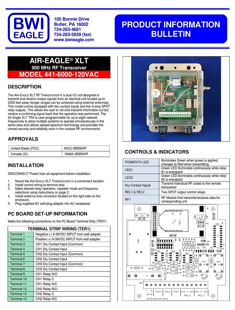
BWI Eagle AIR-EAGLE XLT Manual

PRODUCT INFORMATION
BULLETIN
105 Bonnie Drive
Butler, PA 16002
724-283-4681
724-283-5939 (fax)
www.bwieagle.com
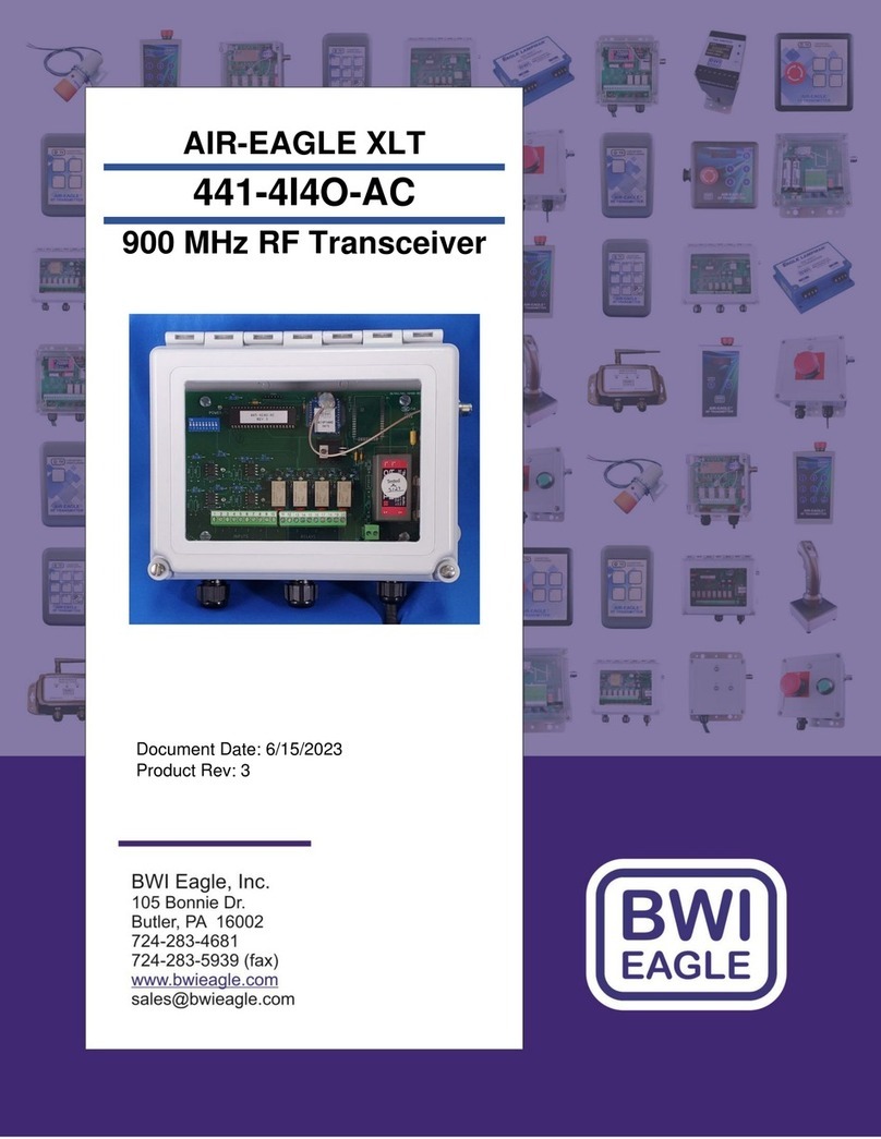
AIR-EAGLE®XLT
900 MHz RF Transceiver
MODEL 44-40100-DC
DESCRIPTION
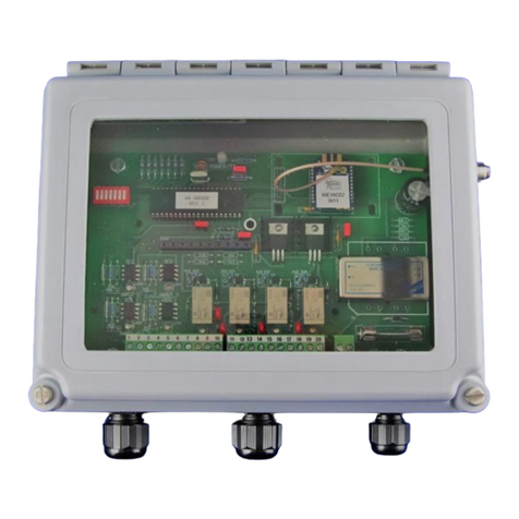
The AIR-EAGLE XLTRFTRANSCEIVER IS a single I/O unitdesigned to
transmit and receive unique signals from another transceiver located upto
2500 feet away. This model comes equipped with a single contact input
and a 5amp SPDT relay output.This allows the user to not only transmit
information out, but receive a confirming signal back that the operation
was performed. The Air-Eagle XLT TRX is user-programmable for up to
seven network frequenciesto allow multiplesystems to operate
simultaneously in the same area and utilizes spread-spectrumtechnology
and provides the utmostsecurity and reliability even in the noisiest RF
environments.A terminal strip has been provided for interfacing with
external dry contact inputs as well as dry contact relay outputs. This unit
canoperate remotemachinery such as pumps, gates, chutes etc.
APPROVALS
United States (FCC)
MCQ-XB900HP
Canada (IC)
1846A-XB900HP
APPLICATIONS
Doors, gates, barriers, tail gates, electrically controlled hydraulicvalves,
propaneshut off controls, winches,anchor lifts, lights, sprinkling systems,
moviescreens, curtains, news weather screens, alarm systems, skeet
throwers, saw mill applications, grain or aggregate chutes, conveyor belts,
boat lifts, and more.
INSTALLATION
DISCONNECT DC Power from all equipment before installation.
1. Mount the AIR-EAGLE XLT TRANSCEIVER in a convenient
location.
2. Install wiring to contact input terminal strip
3. Install antenna onto connector located onthe right side on the
enclosure.
4. Connect DC power to the proper terminals in your control
circuit.
TERMINAL STRIP WIRING
TER 3
DRY CONTACT INPUT
TER 2
RELAY OUTPUT
TER 1
AC/DC POWER INPUT
1
Input 1 C
1
N/O
1
(-) 9-36VDC
2
Input 1
2
C (common)
2
(+) 9-36VDC
3
N/C
3
Not Used
Dimensions (with mounting plate) 7.07L x 3.57W x 1.62H
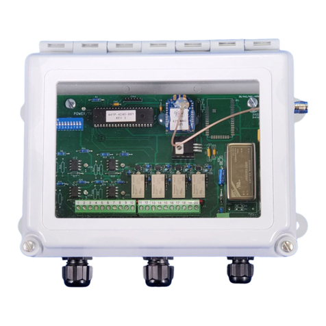
CONTROLS AND INDICATORS
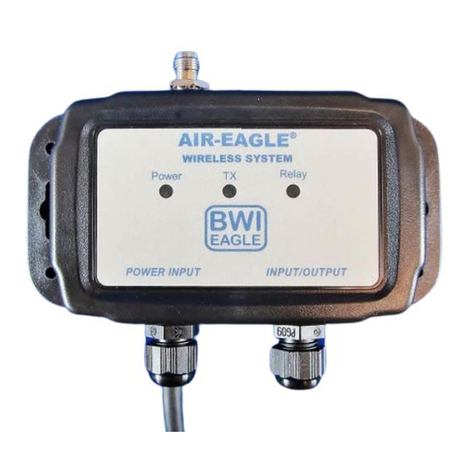
Power –LED1
Illuminates green when unit is powered
TX –LED2
Illuminates red when unit is transmitting
Relay –LED3
Illuminates green whenrelay is energized
RF1
RF module that sends data to the remote
receiver
SEL1
Seven dip switches for selecting options and
network frequency
TER3
Dry contact input
TER2
Relay output
TER1
Power Input
AIR-EAGLE®XLT
900 MHz RF Transceiver
MODEL 44-40100-DC
RELAY & FREQUENCY SET-UP
The unit is shipped from the factory with SEL1 switches in the open
positions. The relay will operate as maintained momentary and unit is
receiving commands on frequency one. If you wish to change these
default settings, follow the instructions onthe table below.
1) Remove power from unit
2) Remove top cover.
3) Select desired relay operation and/or network frequency using table
below.
4) Reattach cover and apply power.
5) Programming is now complete.
RELAY CONFIGURATION
SEL1
(SW1-2)
Relay Operation
SW1
SW1
Momentary (default)
OPEN
OPEN
Toggle/Latch
CLOSED
OPEN
Latching
OPEN
CLOSED
OPTIONS
SW3
Vibrating Feedback Off
Vibrating Feedback On
SW4**
Repeater Function Off (default)
Repeater Function On
Maintained Momentary –Relay mimics button or input –when
depressed or closed, relay will be energized; when released, relay de-
energizes
Toggle/Latch –Relay changes (and holds) its state each time the
corresponding button or input is depressed or closed.
Latching –Relay requires two buttons or inputs for operation –
momentary press of 1st button energizes relay; momentary press of 2nd
button de-energizes relay
** EnableSW4 Repeater Function in ONLY one Receiver per System
FREQUENCY SET-UP
SEL1
(SW5-7)
Network
Frequency
SW5
SW6
SW7
1 (default)
OPEN
OPEN
OPEN
2
CLOSED
OPEN
OPEN
3
OPEN
CLOSED
OPEN
4
CLOSED
CLOSED
OPEN
5
OPEN
OPEN
CLOSED
6
CLOSED
OPEN
CLOSED
7
OPEN
CLOSED
CLOSED
FACTORY PROGRAMMED CHANNEL
OPTIONS
The 44-40100 can be factory programmed to operate on separate
channels for use with multi I/O transceivers. The default is channel 1, but if
you’d like your unit to transmit and receive different channel information,
usethe following part numbers for ordering:
Model 44-40100-2
Will TXand RX Channel 2 info
Model 44-40100-3
Will TXand RX Channel 3 info
Model 44-40100-4
Will TXand RX Channel 4 info
Model 44-40100-5
Will TXand RX Channel 5 info
Model 44-40100-6
Will TXand RX Channel 6 info
Model 44-40100-7
Will TXand RX Channel 7 info
Model 44-40100-8
Will TXand RX Channel 8 info
etc…
SPECIFICATIONS
DC Input
9 –36 VDC @ 10 Watts
RF Output Power
250 mW
Transmit Data
Dry-Contact Input
Relay Contact
SPDT 5 amp @ 120VAC or 30VDC per
channel
Fuse Protected
1 amp
Receiver Range
Up to 2500 Ft. with Standard Antenna –
Up to 4 Miles with External High Gain
Antenna
Receiver Frequency
900 MHz Spread Spectrum
Receiver Channels
Seven independent network frequencies
Operating Temperature
-40oF to +185oF
Enclosure
Polycarbonate NEMA 4, 12, 13 –IP66
Weight
Approx 2 lbs.
DIMENSIONS
REPLACEMENT PARTS & ACCESSORIES
PC Board (Main)
44-40102-DC
Standard Antenna (Included):
900MHz Portable Antenna (For distances up
to 2500 feet*)
49-1103
Optional Antennas and Accessories –
Used to increase range in both non line of sight and line of sight
applications. - Contact BWI Eagle for recommendations
900MHz Omni Directional Antenna (For
distances up to 2 miles*)
49-3101
900MHz 13dB Yagi Antenna
Long Range Operation (For distances up to
4 miles*)
49-3102
Flex Coax Cable w/Connectors
49-4000-XX
(XX = # of Feet)
2 Ft. Bulkhead Assembly (Used when
mounting receiver inside another enclosure)
49-5004-2-ISO
AIR-EAGLE®XLT
900 MHz RF Transceiver
MODEL 44-40100-DC
LIMITED WARRANTY STATEMENT
BWI Eagle Inc. warrants the Air-Eagle Remote Control System, if properly
used and installed, will be free from defects inmaterial and workmanship
for a period of 1 year after date of purchase. Said warranty to include the
repair or replacement of defective equipment. This warranty does not
cover damage due to external causes, including accident, problems with
electrical power, usage not in accordance with product instructions,
misuse, neglect, alteration, repair,improperinstallation, or improper
testing. This limited warranty, and any implied warranties that may exist
under state law, apply only to the original purchaser of the equipment, and
last only for as long as such purchaser continues to owntheequipment.
This warranty replaces all other warranties, express or implied including,
but not limited to, the implied warranties ormerchantability and fitness for
a particular purpose. BWI Eaglemakes no express warranties beyond
thosestatedhere. BWI disclaims without limitation, implied warranties of
merchantability and fitness for a particular purpose. Some jurisdictions do
not allowthe exclusion of implied warranties so this limitation may not
apply to you. To obtain warranty service, contact BWI Eagle for a return
material authorization. When returning equipment to BWI Eagle, the
customer assumes the risk of damage or loss duringshipping and is
responsible forthe shipping costs incurred.
DOCUMENT DATE: 08/05/19 / PRODUCT REV. 5
105 Bonnie Drive
Butler, PA 16002
(724) 283-4681
Fax (724) 283-5939
www.bwieagle.com

Other manuals for AIR-EAGLE XLT

40

This manual suits for next models

1

Other BWI Eagle Transceiver manuals

BWI Eagle AIR-EAGLE XLT 441-40400-DC Manual

BWI Eagle

BWI Eagle AIR-EAGLE XLT 441-40400-DC Manual

BWI Eagle AIR-EAGLE SR PLUS 36-6000-DC Manual

BWI Eagle

BWI Eagle AIR-EAGLE SR PLUS 36-6000-DC Manual

BWI Eagle AIR-EAGLE XLT 441-40100-AC Manual

BWI Eagle

BWI Eagle AIR-EAGLE XLT 441-40100-AC Manual

BWI Eagle AIR-EAGLE SR PLUS 36-40100-AC Manual

BWI Eagle

BWI Eagle AIR-EAGLE SR PLUS 36-40100-AC Manual

BWI Eagle AIR-EAGLE XLT PLUS 461-8000-VBR-AC Manual

BWI Eagle

BWI Eagle AIR-EAGLE XLT PLUS 461-8000-VBR-AC Manual

BWI Eagle AIR-EAGLE XLT Manual

BWI Eagle

BWI Eagle AIR-EAGLE XLT Manual

BWI Eagle AIR-EAGLE XLT 441-4I4O-DC User manual

BWI Eagle

BWI Eagle AIR-EAGLE XLT 441-4I4O-DC User manual

BWI Eagle AIR-EAGLE SR PLUS Manual

BWI Eagle

BWI Eagle AIR-EAGLE SR PLUS Manual

BWI Eagle AIR-EAGLE XLT Manual

BWI Eagle

BWI Eagle AIR-EAGLE XLT Manual

BWI Eagle AIR-EAGLE XLT PLUS 461-40800-AC User manual

BWI Eagle

BWI Eagle AIR-EAGLE XLT PLUS 461-40800-AC User manual

BWI Eagle AIR-EAGLE XLT Manual

BWI Eagle

BWI Eagle AIR-EAGLE XLT Manual

BWI Eagle AIR-EAGLE XLT 44-40100-AC Manual

BWI Eagle

BWI Eagle AIR-EAGLE XLT 44-40100-AC Manual

BWI Eagle AIR-EAGLE XLT User manual

BWI Eagle

BWI Eagle AIR-EAGLE XLT User manual

BWI Eagle AIR-EAGLE XLT PLUS Manual

BWI Eagle

BWI Eagle AIR-EAGLE XLT PLUS Manual

BWI Eagle AIR-EAGLE SR PLUS Manual

BWI Eagle

BWI Eagle AIR-EAGLE SR PLUS Manual

BWI Eagle AIR-EAGLE SR PLUS 36-40100-DC Manual

BWI Eagle

BWI Eagle AIR-EAGLE SR PLUS 36-40100-DC Manual

BWI Eagle AIR-EAGLE XLT PLUS 461-20800-AC Manual

BWI Eagle

BWI Eagle AIR-EAGLE XLT PLUS 461-20800-AC Manual

BWI Eagle AIR-EAGLE XLT 441AN-6000-4-20O-120VAC Manual

BWI Eagle

BWI Eagle AIR-EAGLE XLT 441AN-6000-4-20O-120VAC Manual

BWI Eagle AIR-EAGLE SR PLUS Manual

BWI Eagle

BWI Eagle AIR-EAGLE SR PLUS Manual

BWI Eagle AIR-EAGLE XLT 441-4I4O-AC User manual

BWI Eagle

BWI Eagle AIR-EAGLE XLT 441-4I4O-AC User manual

BWI Eagle AIR-EAGLE XLT 461-40400-DC Manual

BWI Eagle

BWI Eagle AIR-EAGLE XLT 461-40400-DC Manual

BWI Eagle AIR-EAGLE SR PLUS 36-4000-DC Manual

BWI Eagle

BWI Eagle AIR-EAGLE SR PLUS 36-4000-DC Manual

BWI Eagle AIR-EAGLE SR PLUS Manual

BWI Eagle

BWI Eagle AIR-EAGLE SR PLUS Manual

BWI Eagle AIR-EAGLE XLT PLUS Manual

BWI Eagle

BWI Eagle AIR-EAGLE XLT PLUS Manual

Popular Transceiver manuals by other brands

Omega WRS232-USB user guide

Omega

Omega WRS232-USB user guide

Kenwood TK-880 series Service manual

Kenwood

Kenwood TK-880 series Service manual

Yaesu FT-2700RH operating manual

Yaesu

Yaesu FT-2700RH operating manual

Chipcon CC1000 manual

Chipcon

Chipcon CC1000 manual

Omnitron Systems Technology FlexPoint 10AUI/T User instructions

Omnitron Systems Technology

Omnitron Systems Technology FlexPoint 10AUI/T User instructions

CeoTronics CT-DECT Base operating instructions

CeoTronics

CeoTronics CT-DECT Base operating instructions

Midland G9 user manual

Midland

Midland G9 user manual

MADD wM-Bus 868 USB Key Quick reference guide

MADD

MADD wM-Bus 868 USB Key Quick reference guide

Xilinx Virtex-7 VC7203 user guide

Xilinx

Xilinx Virtex-7 VC7203 user guide

Kenwood 144MHz FM TRANSCEIVER K2E Service manual

Kenwood

Kenwood 144MHz FM TRANSCEIVER K2E Service manual

TMC Radio SRM9010 Service manual

TMC Radio

TMC Radio SRM9010 Service manual

ATIM ARM-N8-LRW user guide

ATIM

ATIM ARM-N8-LRW user guide

Cisco FM3500 Endo Installation and configuration manual

Cisco

Cisco FM3500 Endo Installation and configuration manual

POLMAR DB-32 user manual

POLMAR

POLMAR DB-32 user manual

Kenwood TK-7108 Service manual

Kenwood

Kenwood TK-7108 Service manual

QRP Labs QMX Assembly manual

QRP Labs

QRP Labs QMX Assembly manual

Intek SL-02 owner's manual

Intek

Intek SL-02 owner's manual

Linksys MFEFX1 Product data

Linksys

Linksys MFEFX1 Product data

manuals.online logo
manuals.online logoBrands
  • About & Mission
  • Contact us
  • Privacy Policy
  • Terms and Conditions

Copyright 2025 Manuals.Online. All Rights Reserved.