C.T.M. HS-928 User manual

Service Manual
This product has passed CE certifications, including GMP Taiwan,
ISO9001, and ISO13485.
※In case of any discrepancy between the illustrations and accessories in this manual
and the actual Scooter, the actual Scooter shall prevail.
※The Company reserves the right to design and modify this scooter.
HS-928
S81201-92800

Table of Contents :
1-1 Repair instructions
2-1 Front shroud parts
2-2 Front frame parts
2-3 Rear shroud parts
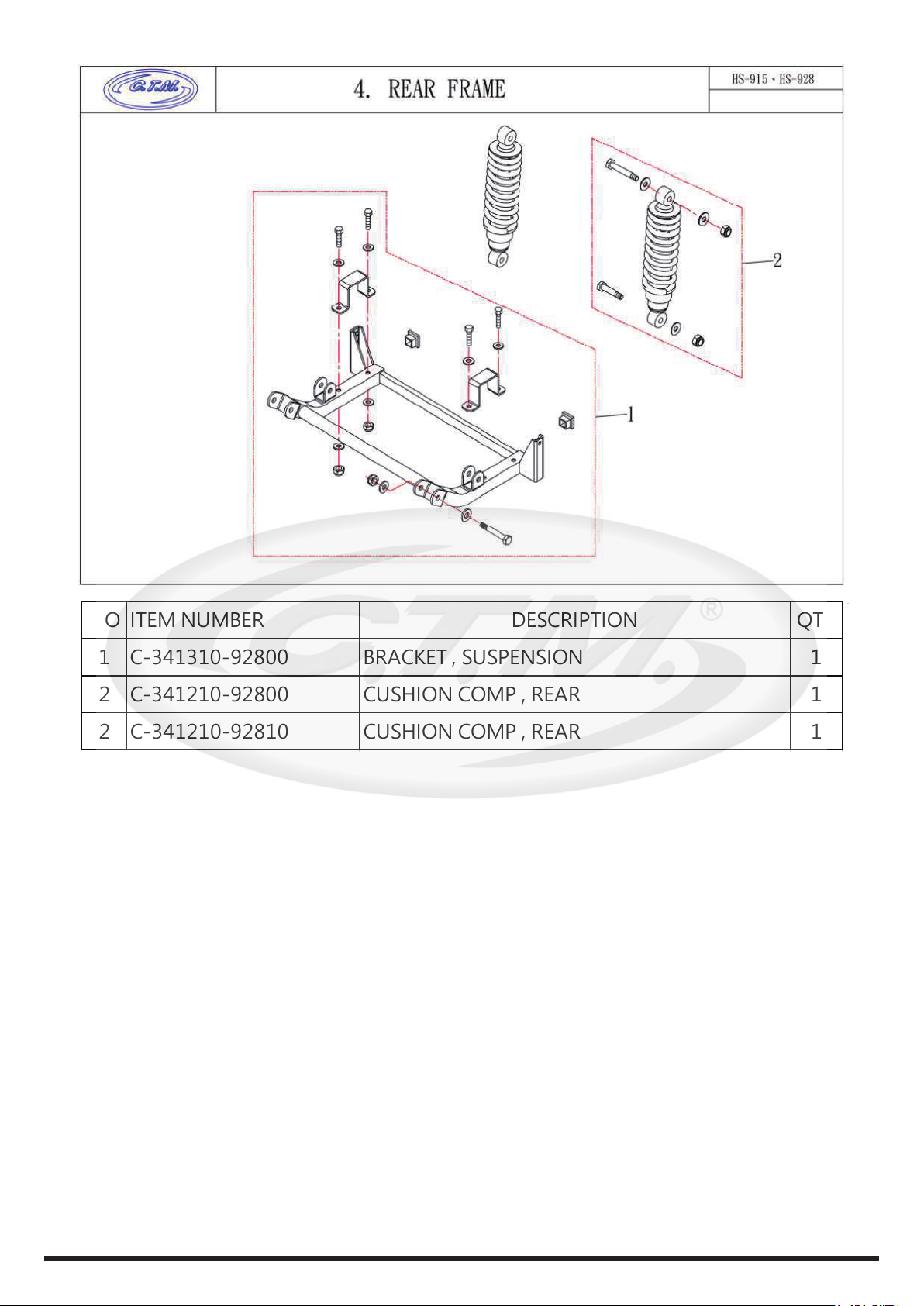
2-4 Rear frame parts
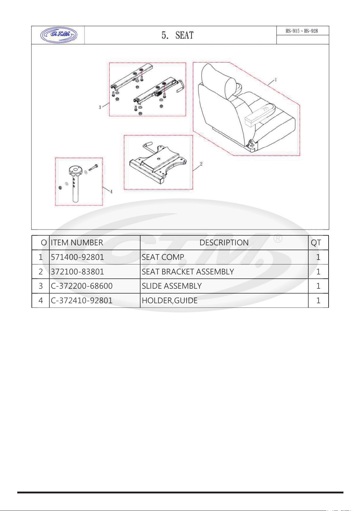
2-5 Seat parts
2-6 Front wheel parts
2-7 Rear wheel parts
2-8 Brake set parts
2-9 Front slanting parts
2-10 Steering parts
2-11 Optional parts
3-1 Battery power-off
3-2 Battery disassembly
3-3 Battery connection cable maintenance
3-4 Battery connection cable set disassembly
3-5 Charging operation instructions
4-1 Main switch and upper control panel instructions
4-2 Upper control panel adjustment
4-3 Control panel maintenance
4-4 Panel wiring instructions
4-5 Maintenance of the VR initiator controller
4-6 Steering cover maintenance
5-1 Front slanting maintenance
5-2 Box back cover maintenance
5-3 Speed reduction maintenance
5-4 Temperature sensor maintenance
5-5 Headlight maintenance
5-6 Front turn light maintenance
5-7 Main power switch maintenance
5-8 charging port maintenance
6-1 Steering frame repair
6-2 Maintenance of front cover of front box
6-3 Front shroud upper cover maintenance
6-4 Front cover maintenance
6-5 Center bar maintenance
7-1 Seat board maintenance
7-2 Seat holder adjustment
7-3 Seat bracket maintenance
7-4 Main controller maintenance
8-1 Front wheel maintenance
8-2 Meter gear maintenance (right front wheel)
8-3 Rear wheel maintenance
8-4 Left/right brake adjustment
8-5 Left/right brake plate maintenance
8-6 Brake lever maintenance
8-7 Rear cover maintenance
8-8 Rear Light maintenance
8-9 Left / right fender maintenance
9-1 Motor maintenance
9-2 Electromagnetic brake maintenance
9-3 Differential mechanism maintenance
9-4 Rear shock absorber maintenance
9-5 Front shock absorber maintenance
9-6 Main cable maintenance
9-7 Brake cable maintenance
........................................................................01
........................................................................04
..........................................................................05
.........................................................................06
..........................................................................07
.....................................................................................08
..........................................................................09
..........................................................................10
.............................................................................09
.......................................................................12
.............................................................................14
.............................................................................15
..........................................................................18
.....................................................................18
........................................19
...................................19
...................................................20
........................22
...................................................23
..........................................................24
..............................................................24
....................................25
........................................................25
..........................................................26
.......................................................26
.....................................................27
................................................28
................................................................28
........................................................29
..................................................29
..........................................................30
...................................................................31
........................................31
.......................................32
.............................................................32
..............................................................33
..............................................................34
................................................................34
...........................................................35
........................................................35
.............................................................36
.................................36
.............................................................37
..........................................................38
...............................................38
..............................................................38
..............................................................39
...............................................................39
....................................................39
......................................................................40
............................................40
...........................................41
..............................................41
..............................................42
..............................................................42
.............................................................44

01
1-1 Repair instructions
Foreword :
※The repair manual is the technical data for maintenance and inspection of all parts of the HS-928.
Its contents are arranged together with pictures and texts, with the key items of "work order",
“work points”, and "inspection and adjustment" in order to provide maintenance standards for
technical personnel.
※If the content and type contained in this repair manual differ slightly from those of the actual scooter,
the actual scooter shall prevail. If the illustrations or instructions of this manual differ from those
of the actual scooter due to a change in the scooter style or structure, the actual scooter shall
prevail. Your understanding is greatly appreciated.
※Regarding all materials, illustrations, instructions, and specifications in this manual, the Company
reserves the right to modify and revise them at any time without notice and free of liability,
according to the latest product information at the time of approval and publication.
※This service manual should not be copied or scanned without permission.
Notes before starting maintenance :
※Please read the service manual carefully before maintenance in order to determine the correct
cause of failure and carry out maintenance.
※Please follow the instructions of the operation procedures in the maintenance manual to avoid
injuries to personnel and damage to the scooter during operation.
※Before performing maintenance on the scooter, it is recommended to first turn off the battery to
prevent the risk of electric shock during maintenance.
※During maintenance, due to the complexity of some steps, the number of maintenance technicians
is suggested to be more than two for better and safer operation.
※When using manual / electric / pneumatic tools, please refer to the torque specification to prevent
damage to the scooter.
※In case of any discrepancy between the illustration in the repair manual and the actual scooter,
the actual scooter shall prevail.
※Please properly preserve the parts of the dismantled scooter to prevent loss.
※A new product does not include screws, gaskets, fixing accessories and other parts. When replacing
the new product, the aforementioned parts disassembled from the old product shall be used to
assemble the new product. If the parts removed from the old product have abnormal phenomena,
such as corrosion, damage, deformation, etc., please replace them first.
※After the scooter is disassembled, please follow the instructions to reassemble it correctly to
prevent scooter damage or personnel injury.
※After the scooter maintenance has been completed, it is recommended to ride/operate the scooter
to confirm that the scooter failure has been eliminated.
※The motor will generate heat when running. If is the scooter needs to be repaired, please wait for
the motor to be cool before operation to prevent burns.
※When repairing the scooter, please put the N-D lever into the D gear to prevent the scooter from
moving.
※It is strictly prohibited to disassemble and repair the scooter when it is powered on.
※Please refer to the instructions on the last page of the service manual for scooter failure.
Personal safety equipment preparation :
•Safety goggles
They can prevent eye damage in case of leakage of lead-acid battery fluid during maintenance.
•Steel-point safety shoes
They can prevent foot injuries when carrying or assembling the scooter.
•Working gloves
When relocating or disassembling iron parts, they can increase friction to effectively hold the
objects. In case of dealing with leakage of lead-acid battery fluid, acid-resistant gloves are needed.
•Repair tools
Please prepare the tools according to the reference tools in the notes for each maintenance item.

02
1-1 Repair instructions
Maintenance instructions :
In order to keep your electric scooter in optimal use, please perform regular maintenance.
Clean and check the following :
※Whether the front/rear tire pressure is within the normal range of 35-40 psi.
※Whether the front/rear tire pattern is lower than the normal value by more than 0.5 mm.
※Whether the frame and components are cleaned.
※Whether the joints and lock points are correct and have signs of corrosion
※Whether the rearview mirror and rear retro reflector are in good condition.
※The motor, battery, controller, and other components do not require maintenance, please do not
disassemble them without authorization. In case of any problems, please immediately send them
for repair.
※The scooter is strictly forbidden from being rinsed with high pressure water in order to prevent
electronic components and wiring from becoming wet and causing accidents.
※
It is strictly forbidden to clean the scooter with corrosive solvents or detergents to prevent discoloration
and deformation of plastic parts and painted surfaces.
※When cleaning the shell, please wipe it with a neutral solution.
※When cleaning the metal part of the scooter shroud, please wipe it with a dry cloth.
※For the internal electrical appliances and wiring of the scooter shroud, please try to avoid contact
with detergents and water. If the surface needs to be wiped, it is recommended to use a dry cloth.
It is recommended that the following parts be oiled and lubricated every 3,000 km or every six months
of use.
1.Front / rear axle
※Oiling is prohibited on the following parts :
shroud, tires, brake drums, electromagnetic brakes, and brake rubber block.
2.Seat holder fixing hole 3.Upper and lower copper
beads set of the center bar

03
2-01 Front shroud parts
2-02 Front frame parts
2-03 Rear shroud parts
2-04 Rear frame parts
2-05 Seat parts
2-06 Front wheel parts
2-07 Rear wheel parts
2-08 Brake set parts
2-09 Front slanting parts
2-10 Steering parts
2-11 Optional parts
Parts Categories

04
NO ITEM NUMBER DESCRIPTION QTY
1 C-332110-92800-RD2 FRONT SHROUD ASSEMBLY 1
1 C-332100-92810-RD2 FRONT SHROUD ASSEMBLY 1
2 C-335110-92800 COVER , BUMPER FRONT 1
2 C-335110-92821 COVER , BUMPER FRONT 1
3 C-313300-92820 BATTERY 12V/100Ah 1
3 C-313300-92830 BATTERY 12V/100Ah 1
3a C-313300-92800 BATTERY ASSEMBLY 12V/100Ah 1
3a C-313300-92810 BATTERY ASSEMBLY 12V/100Ah 1
3a C-313275-92800 BATTERY 12V/75Ah 1

05
NO ITEM NUMBER DESCRIPTION QTY
1 531100-92822 FRAME COMP. , FRONT 1
1 531100-92833 FRAME COMP. , FRONT 1
2 C-317100-92800 CONTROLLER 160A 1
3 336110-92800 BAR ASSEMBLY 1
4 C-336215-56000 BALLS SET. 1
5 526680-52800 PADLOCK 1
6 C-331160-91500 HOLDER , SEAT LOWER BRACKET 1
7 C-315618-92801 Battery,Thermal Circuit Breaker 1
7a C-315300-92800 WIRE HARNESS BATTERY OUTPUT 1
8 C-315650-92800 Wire Controller Socket 1
9 515000-92801 WIRE HARNESS 1
10 317920-52000 GYROSCOPE 1
11 515170-92800 TEMPERATURE SENSOR 1
12 542220-72000 BAND , BATTERY COMP. 1

06
NO ITEM NUMBER DESCRIPTION QTY
1 C-342100-92800-RD2 SHROUD REAR COMP. 1
1 C-342100-92820-RD2 SHROUD REAR COMP. 1
2 C-345100-92800 COVER , BUMPER REAR ASSEMBLY 1
2 C-345100-92810 COVER , BUMPER REAR ASSEMBLY 1
2 C-345100-92820 COVER , BUMPER REAR ASSEMBLY 1
2 C-345100-92831 COVER , BUMPER REAR ASSEMBLY 1
3 C-342150-92801 FENDER RIGHT 1
4 C-342160-92801 FENDER LEFT 1

07
NO ITEM NUMBER DESCRIPTION QTY
1 C-341310-92800 BRACKET , SUSPENSION 1
2 C-341210-92800 CUSHION COMP , REAR 1
2 C-341210-92810 CUSHION COMP , REAR 1

08
NO ITEM NUMBER DESCRIPTION QTY
1 571400-92801 SEAT COMP 1
2 372100-83801 SEAT BRACKET ASSEMBLY 1
3 C-372200-68600 SLIDE ASSEMBLY 1
4 C-372410-92801 HOLDER,GUIDE 1

09
NO ITEM NUMBER DESCRIPTION QTY
1 C-361200-92812 FRONT WHEEL ASSEMBLY 1
1 C-361200-92820 FRONT WHEEL ASSEMBLY 1
1 C-361200-92830 FRONT WHEEL ASSEMBLY 1
2 C-333310-92800 SUSEPNSION ASSEMBLY, FRONT WHEEL R 1
3 C-333410-92800 SUSEPNSION ASSEMBLY, FRONT WHEEL L 1
4 C-334110-92800 AXLE COMP., FRONT WHEEL R 1
5 C-334120-92800 AXLE COMP., FRONT WHEEL L 1
6 C-333210-92800 CUSHION COMP. 1
7 C-333130-92800 FRONT ROD ASSEMBLY 1
7 C-333130-92810 FRONT ROD ASSEMBLY 1
8 C-333140-92800 REAR ROD ASSEMBLY 1
8 C-333140-92810 REAR ROD ASSEMBLY 1
9 C-333305-92800 BOLT , SUSEPNSION COMP.(M10 X 230L) 1
10 517820-92800 METTER GEAR 1
11 517830-92801 WIRE, METTER GEAR 1

10
NO ITEM NUMBER DESCRIPTION QTY
1 C-351000-92800 DIFFERENTIAL COMP. 1
1 C-351000-91500 DIFFERENTIAL COMP. 1
2 C-311100-91511 MOTOR ASSEMBLY 15km 1
2 C-311100-91531 MOTOR ASSEMBLY 15km 1
2 C-311100-91521 MOTOR ASSEMBLY 12.8km 1
2 C-311100-91541 MOTOR ASSEMBLY 12.8km 1
2 C-311100-92881 MOTOR ASSEMBLY 18km (928) 1
2 C-311100-91550 MOTOR ASSEMBLY 15km (1100W) 1
3 C-362000-92812 REAR WHEEL ASSEMBLY 1
3 C-362000-92820 REAR WHEEL ASSEMBLY 1
4364340-56000 WHEEL , ANTI-TIPPER 1

11
NO ITEM NUMBER DESCRIPTION QTY
1 565310-92800 CABLE 1
2 C-365110-92801 PANEL,REAR BRAKE CAM R 1
3 C-365210-92801 PANEL,REAR BRAKE CAM L 1

12
NO ITEM NUMBER DESCRIPTION QTY
1 C-324310-92801-RD2 FRONT SLANTING LID COMP. 1
1 C-324310-92812-RD2 FRONT SLANTING LID COMP. 1
1 C-324310-92821-RD2 FRONT SLANTING LID COMP. 1
1 C-324310-92841-RD2 FRONT SLANTING LID COMP. 1
2 C-324320-92820 BOX ASSEMBLY , KEY TYPE:A01 1
2 C-324320-92830 BOX ASSEMBLY , RANDOM KEY TYPE 1
2 C-324320-92840 BOX ASSEMBLY , KEY TYPE:A01 1
2 C-324320-92850 BOX ASSEMBLY , RANDOM KEY TYPE 1
3 C-324120-92801-RD2 COVER , STEERING FRONT ASSEMBLY 1
3 524120-92801-RD2 COVER , STEERING FRONT 1
4 C-324130-92801 COVER , STEERING REAR 1
5 C-324110-92800 COVER , STEERING UPPER ASSEMBLY 1
5 C-324110-92810 COVER , STEERING UPPER ASSEMBLY 1
5 C-324110-92820 COVER , STEERING UPPER ASSEMBLY 1
6 C-318100-92800 HEAD LAMP COMP 1
6 C-318120-92800 HEAD LAMP COMP 1

13
7 C-318300-92800 LAMP ASS’Y,FRONT TURN SIGNAL-R 1
7 C-318320-92800 LAMP ASS’Y,FRONT TURN SIGNAL-R 1
8 C-318400-92800 LAMP ASS’Y,FRONT TURN SIGNAL-L 1
8 C-318420-92800 LAMP ASS’Y,FRONT TURN SIGNAL-L 1
9 525210-61500 COVER , STEERING JOINT 1
10 C-324335-92800 GUARD+VEL-CRO 1

14
NO ITEM NUMBER DESCRIPTION QTY
1 521100-92801 STEERING COMP. 1
2 C-321220-92800 GRIP , HANDLE BAR 1
3 C-316300-57001 STARTER ASSEMBLY 1
4 C-326120-68600 LEVER , BRAKE RIGHT 1
5 C-325300-89003 STEERING ADJ ASSEMBLY 1
6 C-325390-92810 REGULATOR ROD 1
7 C-325120-89001 JOINT B,STEERING ADJ LOWER 1
8 326200-92800 BACK MIRROR COMP 1
9 C-314280-89001 CHARGER COMP. 24DCV/8.0Amp 1
9 C-314280-89011 CHARGER COMP. 24DCV/8.0Amp 1
9a C-314215-92820 CHARGER COMP. 24DCV/15.0Amp. 1
9b C-314812-92800 CHARGER COMP. 24DCV/12.0Amp 1
10 515190-85500 TIE, WIRE HARNESS 1

15
NO ITEM NUMBER DESCRIPTION QTY
1 377200-92800 CANE HOLDER COMP 1
2 377300-28000 OXYGEN CYLINDER COMP 1
3 377100-28001 BRACKET COMP., CANE 1
4 377600-28000 BRACKET ASSEMBLY , WALKER 1
5 377400-28000 REAR BASKET COMP. 1
6 379830-92800 GOLF HOLDER ASSEMBLY 1
7 C-331160-72800 LIFTING GEAR ASSEMBLY 1
8 7-ABL0 SHROUD TOUCH UP PAINT BL0 1
8 7-ABU1 SHROUD TOUCH UP PAINT BU1 1
8 7-ABU4 SHROUD TOUCH UP PAINT BU4 1
8 7-ABU6 SHROUD TOUCH UP PAINT BU6 1
8 7-AGR3 SHROUD TOUCH UP PAINT GR3 1
8 7-AGY5 SHROUD TOUCH UP PAINT GY5 1
8 7-AGY7 SHROUD TOUCH UP PAINT GY7 1
8 7-ARD2 SHROUD TOUCH UP PAINT RD2 1
8 7-ARD6 SHROUD TOUCH UP PAINT RD6 1

16
8 7-ASG1 SHROUD TOUCH UP PAINT SG1 1
8 7-ASG5 SHROUD TOUCH UP PAINT SG5 1
8 7-AWH1 SHROUD TOUCH UP PAINT WH1 1

17
3-1 Powering off the battery
3-2 Battery removal
3-3 Battery connection cable set maintenance
3-4 Battery connection cable set disassembly
3-5 Charging operation instructions
4-1 Main switch and upper control panel instructions
4-2 Upper control panel adjustment
4-3 Control panel maintenance
4-4 Panel wiring instructions
4-5 Maintenance of the VR initiator controller
4-6 Steering cover maintenance
5-1 Front slanting maintenance
5-2 Box rear cover maintenance
5-3 Microswitch set maintenance
5-4 Temperature sensor maintenance
5-5 Headlight maintenance
5-6 Front turn light maintenance
5-7 Main power switch set maintenance
5-8 charging port maintenance
6-1 Steering frame repair
6-2 Maintenance of front cover of front box
6-3 Front shroud upper cover maintenance
6-4 Front cover maintenance
6-5 Center bar maintenance
7-1 Seat board maintenance
7-2 Seat holder adjustment
7-3 Seat bracket maintenance
7-4 Main controller maintenance
8-1 Front wheel maintenance
8-2 Meter gear maintenance (wheel-FR)
8-3 Rear wheel maintenance
8-4 Left/right brake adjustment
8-5 Left/right brake plate maintenance
8-6 Brake lever maintenance
8-7 Rear cover maintenance
8-8 Rear Light maintenance
8-9 Left / right fender maintenance
9-1 Motor maintenance
9-2 Electromagnetic brake maintenance
9-3 Differential mechanism maintenance
9-4 Rear shock absorber maintenance
9-5 Front shock absorber maintenance
Maintenance Manual :

18
3-1 Powering off the battery :
3-2 Battery removal :
5.Remove the upper cover of
the rear shroud of the scooter.
※Before performing maintenance on the scooter, first cut off the power. If the power is
not cut off first, it may cause the risk of electric shock.
※Before performing maintenance on the scooter, please park it in an open space on level
ground and make sure the N-D lever is put in “D.”
※The battery itself is very heavy. Please be careful not to carry more than you can handle.
※The positive and negative terminals on the battery should not be touched with metal
tools to prevent the risk of danger.
6.Remove the scooter power
connector (1pcs). ※Power cut-off is completed.
※
Please follow the above steps
in reverse for reassembly.
※Sleeve Tool #10 x 1pcs ※Cross Tool
1.Refer to 3-1 Powering off the battery to first power off the scooter.
2.Loosen the entire belt.
3.Remove the positive terminal on both the battery connection cable and the battery.
4.Remove the negative terminal on both the battery connection cable and the battery.
5.Remove the positive and negative terminals on both the battery power cable and the battery.
6.The battery can now be removed.
※Please follow the above steps in reverse for reassembly and replacement.
4.
4.
3.
2.
6.
5.
4. 3.
※No tools required
1.Ensure the scooter’s power is off.
2.Adjust the gearshift of the scooter to “D.”
3.Pull the handle on the left side of the seat.
4.Remove the scooter seat.
Table of contents
Other C.T.M. Scooter manuals

C.T.M.
C.T.M. 5 series User manual

C.T.M.
C.T.M. HS-290 User manual

C.T.M.
C.T.M. HS-730 User manual

C.T.M.
C.T.M. 2 Series User manual

C.T.M.
C.T.M. HS-850 User manual

C.T.M.
C.T.M. HS-125 User manual

C.T.M.
C.T.M. HS-290 User manual

C.T.M.
C.T.M. HS-539 User manual

C.T.M.
C.T.M. HS-588 5 series User manual

C.T.M.
C.T.M. HS-115 User manual

C.T.M.
C.T.M. HS-915 User manual

C.T.M.
C.T.M. HS-320 User manual

C.T.M.
C.T.M. 7 Series User manual

C.T.M.
C.T.M. HS-300E User manual

C.T.M.
C.T.M. HS-855 User manual

C.T.M.
C.T.M. HS-570 User manual

C.T.M.
C.T.M. HS-295E User manual

C.T.M.
C.T.M. HS-559 User manual

C.T.M.
C.T.M. HS-575 User manual

C.T.M.
C.T.M. HS-665 User manual