CAME MR8204 User manual

1
2
3
48
5
6
7
MR8204
TECHNICAL SPECIFICATIONS
1. cover
2. radar antenna (wide field)
3. radar field size adjustment
4. IR-prism (2 m)
DESCRIPTION
Presence
Typical response time: <256 ms
Active infrared with background analysis
Spot diameter: 0.1 m (typ)
Number of spots: 24
Number of curtains: 2
From -4 ° to +4 ° (adjustable)
Solid-state-relay
(free of potential, free of polarity)
Max. contact current: 100 mA
Max. contact voltage: 42 V AC/DC
0.3 s to 1 s (not adjustable)
Typical: < 5 ms
ENGLISH
5. main connector
6. IR-angle adjustment
7. push button for setup or DIP-setting confirmation
8. DIP-switch
12 V - 30 V DC -5%/+10% (to be operated from SELV compatible power supplies only)
< 2.2 W
1.8 m to 3 m
< 1 V : Log. L; > 10 V: Log. H (max. 30 V)
-25 °C to +55 °C
IP54
< 70 dB
20 years
R&TTE 1999/5/EC; MD 2006/42/EC; LVD 2006/95/EC; ROHS 2 2011/65/EU; EN 16005:2012;
EN 12978:2009; EN IEC 62061:2005 SIL2, EN 61496-1:2012 ESPE Type 2; EN ISO 13849-1:2008
Pl «c» CAT.2 (under the condition that the door control system monitors the sensor at least once per door cycle)
Supply voltage:
Power consumption:
Mounting height:
Sensitivity of the test input:
Temperature range:
Degree of protection:
Noise:
Expected lifetime:
Norm conformity:
Motion
Min. detection speed: 5 cm/s
Microwave doppler radar
Transmitter frequency: 24.150 GHz
Transmitter radiated power: < 20 dBm EIRP
Transmitter power density: < 5 mW/cm2
From 15 ° to 50 ° vertical (adjustable)
Solid-state-relay
(free of potential, free of polarity)
Max. contact current: 100 mA
Max. contact voltage: 42 V AC/DC
0.5 s
Detection mode:
Technology:
Angle:
Output:
Hold time output signal:
Response time on test request:
User’s Guide for product version 0100 and higher. See product label for serial number.
Specifications are subject to changes without prior notice. All values measured in specific conditions
.
GREEN
LED
RED
LED
MR8204 / FA00025M06 ☜☞ VIO-DT2 / 42.8274 / v2 - 02.15
Opening & safety sensor
for automatic sliding doors
Other use of the device is outside the permitted purpose and can not be guaranteed by the manufacturer.
The manufacturer cannot be held responsible for incorrect installations or inappropriate adjustments of the sensor.

1
2
3
0
1
2
12
0
1
2
33
0
1
«click»
12-30 V DC
1
1
H
W
2 m
max.
5 cm
MIN MAX
max. 5 cm
+
-
+
-
2.2 m 2.2 m
field size: max
4 x 2 m
1 x 0.5 m
MOUNTING & WIRING
RADAR FIELD - OPENING IMPULSE
FIELD SIZE
ANGLE
GREEN
LED
RED
LED
1Output status when sensor is operational
2For compliance with EN 16005, connection
to door controller test output is required.
2.2 m
The door control unit and the door cover profile must be correctly earthed.
Check position of IR-curtains with
Spotfinder and adjust if necessary.
ANGLE
Detection field width indicated according to conditions defined in EN 16005 and including dimension of test body CA.
INFRARED FIELD - SAFETY
WIDTH
HW
2.20 m 2.30 m
2.50 m 2.55 m
3.00 m 2.80 m
* in standard presetting
GREEN
BROWN
YELLOW
WHITE
PINK
GREY
RED2
BLUE2
POWER SUPPLY
OPENING INPUT
OPENS DOOR
SAFETY INPUT
KEEPS DOOR OPEN
TEST
OUTPUT
RELAY R1
RELAY R2
DOOR
CLOSER
CLOSER
AWAY
AWAY
SENSOR
The size of the detection field varies according to the mounting height of the sensor.
ORANGE
@ 2.2 m:
Depth of curtain : 8-10 cm
Depth of safety field: 25 cm*
MR8204 / FA00025M06 ☜☞ VIO-DT2 / 42.8274 / v2 - 02.15

4
5
+
+
- Test the good functioning of the installation before leaving the premises.
- The device cannot be used for purposes other than its intended use. All other uses cannot be guaranteed by the manufacturer
of the sensor.
- The manufacturer of the door system is responsible for carrying out a risk assessment and installing the sensor and the door system
in compliance with applicable national and international regulations and standards on door safety.
- The manufacturer of the sensor cannot be held responsible for incorrect installations or inappropriate adjustments of the sensor.
- Only trained and qualified personnel may install and setup the sensor.
- The warranty is void if unauthorized repairs are made or attempted by unauthorized personnel.
- Avoid touching any electronic and optical components, avoid vibrations, do not cover the sensor and avoid proximity to
neon lamps or moving objects.
- It is recommended to clean the optical parts at least once a year or more often if required due to environmental conditions.
PRESETTINGS ENVIRONMENT RELAY R1 ACTIVATION
SAFETY INSTRUCTIONS
TIP: Launch an ASSISTED SETUP to verify wiring, position of the
curtains and correct functioning of the sensor.
SETTINGS (by DIP-switch)
QUICK SETUP ASSISTED SETUP
SETUP
Step outside of the infrared field before launching a setup.
LONG (> 3s)
SHORT
standard
critical
environment
shopping
street1
hospital2
standard
extreme3
1 Can only be used if DIP 4 is OFF.
2 Not available on MR8204. If selected, the presetting «standard» is applicable.
3Enhanced IR-immunity which excludes EN 16005-conformity of the door system.
4The opening relay (R1) is activated in case of detection in the radar or infrared field.
motion
or
presence4
motion
After changing a DIP-switch, the orange LED flashes.
A LONG push on the push button confirms the setting.
Always launch a setup after changes of the DIP-settings.
LONG (> 3s)
critical environment: enhanced immunity (rain, snow, lamps...) and only 1 IR-curtain activated.
shopping street: optimized for narrow sidewalks > the opening relay (R1) is activated in case of detection in radar + IR-field.
hospital: optimized for persons with reduced mobility (PRM)
standard: standard environments (factory setting)
OFF
RED-GREEN
RED-GREEN OFF OFF
OPEN+CLOSE
ORANGE
MR8204 / FA00025M06 ☜☞ VIO-DT2 / 42.8274 / v2 - 02.15

2
1
4
5
1
2
1
1
2
1
2
1
2
1
2
1
1
2
1
2
1
1
1
1
1
2
1
1
2
1
2
Came S.p.A.- Via Martiri Della Liberta 15 - IT-31030 DOSSON DI CASIER (TV)
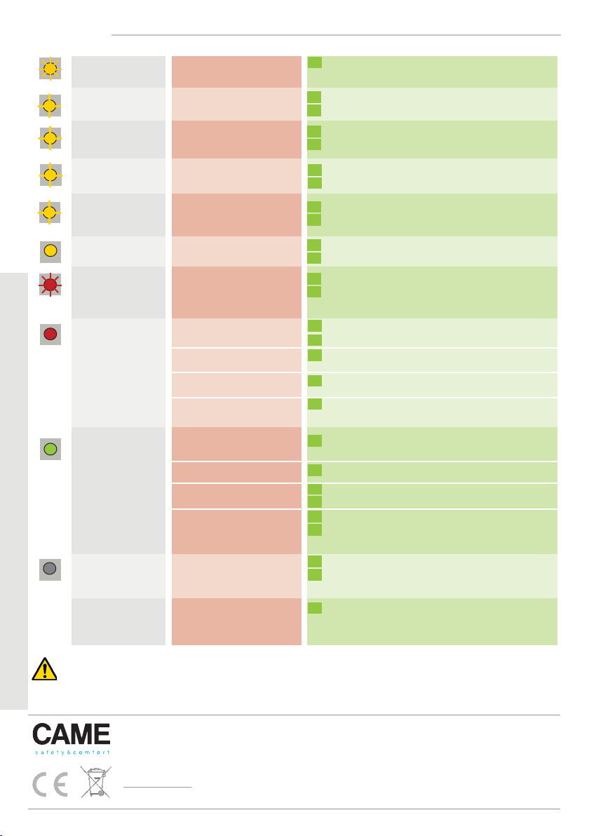
LED-SIGNALS
The ORANGE LED
flashes 1 x.
The ORANGE LED
flashes 2 x.
The ORANGE LED
flashes 4 x.
The ORANGE LED
flashes 5 x.
The ORANGE LED
flashes quickly.
The ORANGE LED
is on.
The RED LED flashes
quickly after an
assisted setup.
The RED LED
lights up
sporadically.
The GREEN LED
lights up
sporadically.
The LED is off.
The reaction of
the door does not
correspond to the
LED-signal.
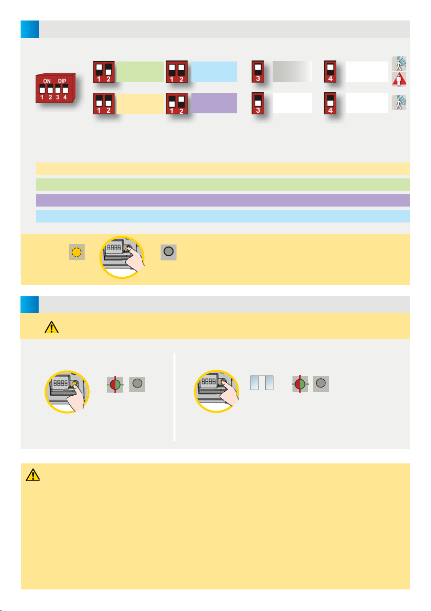
A DIP-switch was changed
without confirmation.
The sensor signals
an internal fault.
Irregularities in the
power supply
The sensor receives
not enough IR-energy.
The sensor receives
too much IR-energy.
The sensor encounters
a memory problem.
The sensor vibrates.
The sensor sees the door
during the assisted setup.
The sensor sees the door.
The sensor is disturbed by
lamps or another sensor.
The sensor is disturbed
by the rain.
The sensor is disturbed by
rain and/or leaves.
The sensor vibrates.
Ghosting
The sensor sees the door
or other moving objects.
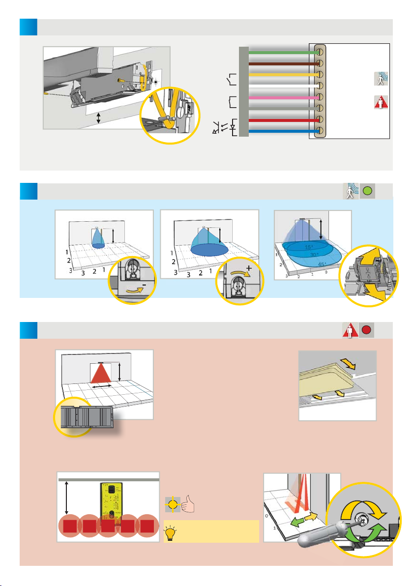
Check power supply.
Check wiring.
Use the 1 m prism if possible (accessory).
Check the angle of the IR-curtains.
Confirm the DIP-settings by a long push on the
push button.
Cut and restore power supply.
If orange LED lights up again, replace sensor.
Check the angle of the IR-curtains.
Launch a new assisted setup.
Attention: Do not stand in the detection field!
Change the activation mode of relay R1 (DIP 4).
Use a low energy prism if possible (accessory).
Check the angle of the IR-curtains.
Check if the sensor is fastened firmly.
Check position of prism and cover.
Choose the critical environment presetting (DIP 1+2).
Change radar antenna angle.
Check if the sensor is fastened firmly.
Check position of cable and cover.
Remove the objects if possible.
Change radar field size.
Launch an assisted setup and adjust the IR angle.
Cut and restore power supply.
If orange LED flashes again, replace sensor.
Check connections to test output.
If your door controller is not able to test the sensor,
connect the red and blue cable to the power supply.*
SAFETY INSTRUCTIONS
The manufacturer of the door system is responsible for carrying out a risk assessment and installing the sensor and the door system
in compliance with applicable national and international regulations and standards on door safety and if applicable, the machinery directive 2006/42/EC.
Only trained and qualified personnel may install and setup the sensor. The warranty is void if unauthorized repairs are made or attempted by unauthorized personnel. Avoid
touching any electronic and optical components.
MR8204 / FA00025M06 ☜Original instructions☞ VIO-DT2 / 42.8274 / v2 - 02.15
Came S.p.A. hereby declares that MR8204 is in conformity with the basic requirements and the other relevant provisions
of the directives 1999/5/EC, 2004/108/EC and 2006/42/CE.
Only for EC countries: According to the European Guideline 2002/96/EC for Waste Electrical and Electronic Equipment
(WEEE)
Original upon request.
BUY-TO-SELL PRODUCT
Other manuals for MR8204
1
Table of contents
Other CAME Accessories manuals