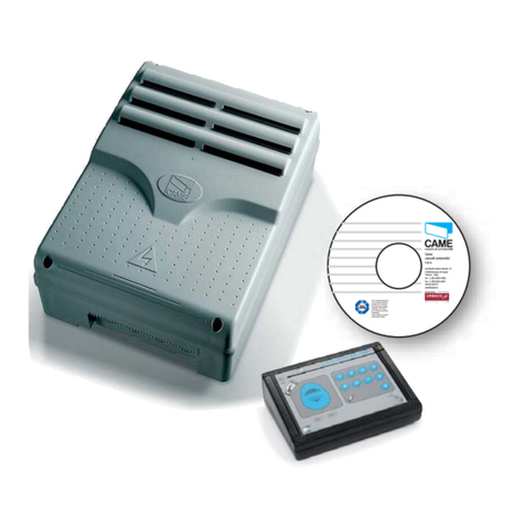
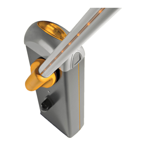
CAME FA01584M4A User manual

FA0 1 58 4 M 4A
88006-0057
IT Italiano
EN English
FR Français
RU Русский
CAME S.p.A.
Via Martiri della Libertà,
15
31030 Dosson di Casier
Treviso - Italy
Tel. (+39) 0422 4940
Fax (+39) 0422 4941
ITALIANO
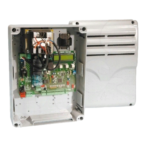
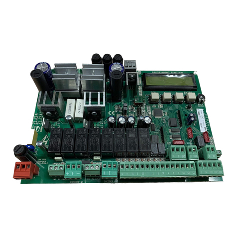
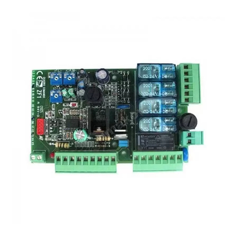
Descrizione componenti della scheda
1Fusibile per gli accessori
2Fusibile per la scheda elettronica
3Morsettiera per l'alimentazione della scheda
elettronica
4Morsettiera per il collegamento dei
dispositivi di segnalazione
5Morsettiera per il collegamento dei
dispositivi di comando
6Display
7Morsettiera per il collegamento dei
dispositivi di sicurezza
8Connettore per scheda Memory Roll
9Connettore per CAME KEY
10 Connettore per scheda RIO CONN
11 Morsettiera per collegamento CRP
12 Connettore per scheda RSE
13 Morsettiera per il collegamento dell'antenna
14 Connettore per scheda radiofrequenza a
innesto (AF)
15 Tasti per la programmazione
16 Morsettiera per dispositivi BUS
17 Morsettiera per il collegamento dei micro di
finecorsa e/o encoder
18 Morsettiera per il collegamento del
motoriduttore con encoder o con interruttore di
rallentamento ed elettroserratura
FA01584M4A - 02/2022
88006-0057

2 - FA01584M4A - 02/2022 - © CAME S.p.A.
Installazione

3 - FA01584M4A - 02/2022 - © CAME S.p.A.
Programmazione
Per la programmazione completa consultare il fascicolo tecnico di 801QA-0050/801QA-0070 su www.came.com ( > documentazione tecnica).
Funzione dei tasti di programmazione
1Tasto ESC
Il tasto ESC permette di eseguire le operazioni di seguito descritte.
Uscire dal menu
Annullare le modifiche
Tornare alla schermata precedente
2Tasti < >
I tasti < > permettono di eseguire le operazioni di seguito descritte.
Navigare attraverso le voci del menu
Incrementare o decrementare un valore
3Tasto ENTER
Il tasto ENTER permette di eseguire le operazioni di seguito descritte.
Entrare nei menu
Confermare la scelta
Fuori dal menu il tasto ESC esegue l'arresto del cancello e i tasti < > eseguono l'apertura e chiusura del cancello.

4 - FA01584M4A - 02/2022 - © CAME S.p.A.
Messa in funzione
Terminati i collegamenti elettrici, procedere con la messa in funzione. L'operazione deve essere eettuata solo da personale esperto e qualificato.
Controllare che l’area di manovra sia libera da qualsiasi ostacolo.
Dare tensione e procedere con le operazioni di seguito indicate.
A1 - Tipo motore
F46 - Numero motori
A2 - Prova motore > apre l'anta M2
< apre l'anta M1
Verificare che entrambe le ante procedano in apertura altrimenti invertire MN sul relativo morsetto.
F2 - Ingresso CX
F3 - Ingresso CY
F72 - Funzione finecorsa*
F73 - Tipo ingressi FC/FA**
A8 - Potenza motore**
A3 - Taratura corsa
*Solo con microswitch di finecorsa utilizzati.
**Solo con tipo motore generico [Funzione A1 impostata su 0].
Se sul display scorre la scritta A1 è necessario impostare il tipo motore prima di modificare altri parametri.
Se sul display scorre la scritta A3 è necessario eseguire la taratura della corsa. Il quadro non accetta comandi di movimentazione ad esclusione della prova motore (A2).
Completata la programmazione, controllare il buon funzionamento dei dispositivi di segnalazione e di sicurezza.
Dopo aver dato tensione all’impianto, la prima manovra è sempre in apertura; attendere il completamento della manovra.
Premere immediatamente il tasto ESC o il pulsante di STOP se si riscontrano anomalie, malfunzionamenti, rumorosità o vibrazioni sospette o comportamenti inattesi
dell’impianto.

5 - FA01584M4A - 02/2022 - © CAME S.p.A.
Esportare / importare dati
È possibile salvare i dati relativi agli utenti e alla configurazione dell'impianto in una scheda MEMORY ROLL.
I dati memorizzati possono essere riutilizzati in un'altra scheda elettronica dello stesso tipo per riportare le stesse configurazioni.
Prima di inserire ed estrarre la scheda MEMORY ROLL, è OBBLIGATORIO TOGLIERE LA TENSIONE DI LINEA.
1Inserire la scheda MEMORY ROLL sul
connettore dedicato presente sulla scheda
elettronica.
2Premere il pulsante Enter per accedere alla
programmazione.
3Usare le frecce per scegliere la funzione
desiderata.
Le funzioni vengono visualizzate solo quando viene inserita una scheda MEMORY ROLL
F50 -Salvataggio dati
Salva nel dispositivo di memoria (memory roll) i dati relativi agli utenti, alle temporizzazioni e alle configurazioni.
F51 -Lettura dati
Carica dal dispositivo di memoria (memory roll) i dati relativi agli utenti, alle temporizzazioni e alle configurazioni.
Terminate le operazioni di salvataggio e caricamento dati è possibile rimuovere la MEMORY ROLL.

6 - FA01584M4A - 02/2022 - © CAME S.p.A.
Messaggi di errore
E1 Errore di taratura del motore M1
E2 Errore di taratura del motore M2
E3 Errore segnale encoder non rilevato
E4 Errore di test servizi fallito
E7 Errore tempo di lavoro
E9 Ostacoli consecutivi rilevati durante la chiusura
E10 Ostacoli consecutivi rilevati durante l'apertura
E11 Errore massimo di ostacoli
E12 Tensione di alimentazione del motore mancante o non suciente
E13 Errore su ingressi finecorsa o finecorsa entrambi aperti
E15 Errore trasmettitore non compatibile
E17 Errore sistema wireless non comunica
E18 Errore sistema wireless non configurato
E24 Errore di comunicazione con i dispositivi BUS
E25 Errore di impostazione indirizzi sui dispositivi BUS

7 - FA01584M4A - 02/2022 - © CAME S.p.A.
ENGLISH
Description of control board components
1Accessories fuse
2Control board fuse
3Terminal board for power supply to the control board
4Terminal board for connecting the signalling devices
5Terminal board for connecting control devices
6Display
7Terminal board for connecting the safety devices
8Memory Roll card connector
9Connector for CAME KEY
10 RIO CONN card connector
11 Terminal board for CRP connection
12 RSE card connector
13 Terminal board for connecting the antenna
14 Connector for plug-in radio frequency card (AF)
15 Programming buttons
16 Terminal board for BUS devices
17 Terminal boards for connecting micro limit switches and/or encoders
18 Terminal board for connecting the gearmotor with encoder or with
slowdown switch and electric lock

8 - FA01584M4A - 02/2022 - © CAME S.p.A.
Installation

9 - FA01584M4A - 02/2022 - © CAME S.p.A.
Programming
For full programming information, please see the technical manual 801QA-0050/801QA-0070 at www.came.com ( > Tech Docs).
Programming button functions
1ESC button
The ESC button is used to perform the operations described below.
Exit the menu
Delete the changes
Go back to the previous screen
2< > buttons
The <> buttons are used to perform the operations described below.
Navigate the menu
Increase or decrease values
3ENTER button
The ENTER button is used to perform the operations described below.
Access menus
Confirm choice
Outside the menu, the ESC key stops the gate and the < > keys open and close the gate.

10 - FA01584M4A - 02/2022 - © CAME S.p.A.
Getting started
Once the electrical connections have been made, proceed with commissioning. Only skilled and qualified sta may perform this operation.
Make sure that there are no obstacles in the way.
Power up and proceed with the operations indicated below.
A1 - Motor type
F46 - Number of motors
A2 - Motor test > open the M2 leaf
< open the M1 leaf
Check that both leaves open. If they do not, invert M and N on the relevant terminal.
F2 - CX input
F3 - CY input
F72 - Limit-switch function*
F73 - Input type FC/FA**
A8 - Motor power**
A3 - Travel calibration
*Only with end-of-travel microswitches used.
**Only with generic motor [Function A1 set at 0].
If “A1” scrolls across the display, this means the type of motor must be set before any other parameters can be modified.
If “A3” scrolls across the display, calibrate the travel. The panel does not accept motion commands, except for the motor test (A2).
Complete programming and check the warning and safety devices are working properly.
After powering up the system, the first manoeuvre is always to open the gate Wait for the manoeuvre to be completed.
Press the ESC button or STOP button immediately in the event of any faults, malfunctions, strange noises or vibrations, or unexpected behaviour in the system.

11 - FA01584M4A - 02/2022 - © CAME S.p.A.
Import/export data
Save user data and system configuration data on a MEMORY ROLL card.
The stored data can be reused for another control board of the same type to carry across the same configuration.
Before inserting and removing the MEMORY ROLL card, DISCONNECT THE MAINS POWER SUPPLY TO THE LINE.
1Insert the MEMORY ROLL card into the
corresponding connector on the control board.
2Press the “Enter” button to access
programming.
3Use the arrows to choose the desired
function.
The functions are displayed only when a MEMORY ROLL card is inserted.
F50 -Save data
Save user data, timings and configurations to the memory device (memory roll).
F51 -Read data
Upload user data, timings and configurations to the memory device (memory roll).
Once the data have been saved and loaded, the MEMORY ROLL can be removed.

12 - FA01584M4A - 02/2022 - © CAME S.p.A.
Error messages
E1 Motor M1 calibration error
E2 Motor M2 calibration error
E3 Encoder signal not detected error
E4 Service test failure error
E7 Operating time error
E9 Consecutive obstacles detected during closing
E10 Consecutive obstacles detected during opening
E11 Maximum number of obstacles
E12 Motor supply voltage missing or insucient
E13 Limit switch input error or both limit switches open
E15 Incompatible transmitter error
E17 Wireless system communication error
E18 Wireless system not configured error
E24 BUS device communication error
E25 Address settings error on BUS devices

13 - FA01584M4A - 02/2022 - © CAME S.p.A.
FRANÇAIS
Description des composants de la carte
1Fusible pour les accessoires
2Fusible pour la carte électronique
3Bornier pour l'alimentation de la carte électronique
4Bornier de connexion des dispositifs de signalisation
5Bornier de connexion des dispositifs de commande
6Acheur
7Bornier de connexion des dispositifs de sécurité
8Connecteur pour carte Memory Roll
9Connecteur pour CAME KEY
10 Connecteur pour carte RIO CONN
11 Bornier de connexion CRP
12 Connecteur pour carte RSE
13 Bornier de connexion de l’antenne
14 Connecteur pour carte radiofréquence enfichable (AF)
15 Touches de programmation
16 Bornier pour dispositifs BUS
17 Bornier de connexion des minirupteurs de fin de course et/ou
encodeurs
18 Bornier de connexion du motoréducteur avec encodeur ou avec
interrupteur de ralentissement et serrure de verrouillage électrique

14 - FA01584M4A - 02/2022 - © CAME S.p.A.
Installation

15 - FA01584M4A - 02/2022 - © CAME S.p.A.
Programmation
Pour la programmation complète, consulter le manuel technique de 801QA-0050/801QA-0070 sur www.came.com (> documentation technique).
Fonction des touches de programmation
1Touche ESC
La touche ESC permet d’eectuer les opérations décrites ci-après.
Sortir du menu
Annuler les modifications
Revenir à la page-écran précédente
2Touches < >
Les touches <> permettent d’eectuer les opérations décrites ci-après.
Naviguer dans les options du menu
Augmenter ou diminuer une valeur
3Touche ENTER
La touche ENTER permet d’eectuer les opérations décrites ci-après.
Entrer dans les menus
Confirmer le choix
Hors du menu, la touche ESC provoque l'arrêt du portail tandis que les touches < > permettent d'obtenir l'ouverture et la fermeture du portail.

16 - FA01584M4A - 02/2022 - © CAME S.p.A.
Mise en fonction
Au terme des branchements électriques, eectuer la mise en marche. L’opération ne doit être eectuée que par du personnel qualifié et spécialisé.
S'assurer que la zone de manœuvre ne présente aucun obstacle.
Mettre sous tension et exécuter les opérations suivantes.
A1 - Type moteur
F46 - Nombre moteurs
A2 - Essai moteur > ouvre le vantail M2
> ouvre le vantail M1
Contrôler que les deux vantaux s'ouvrent, dans le cas contraire inverser MN sur la borne correspondante.
F2 - Entrée CX
F3 - Entrée CY
F72 - Fonction fin de course*
F73 - Type entrées FC/FA**
A8 - Puissance moteur**
A3 - Auto-apprentissage de la course
*Uniquement avec les micro-interrupteurs de fin de course utilisés.
**Uniquement avec type moteur général [Fonction A1 configurée sur 0].
Si A1 défile à l'écran, il faut configurer le type de moteur avant de modifier d'autres paramètres.
Si A3 défile à l'écran, il faut eectuer l'auto-apprentissage de la course. L'armoire n'accepte aucune commande de mouvement, à l'exception du test moteur (A2).
Au terme de la programmation, contrôler le bon fonctionnement des dispositifs de signalisation et de sécurité.
Après avoir mis l'installation sous tension, la première manœuvre a toujours lieu en ouverture; attendre l’exécution complète de la manœuvre.
Appuyer immédiatement sur la touche ESC ou le bouton d'ARRÊT (STOP) en cas d’anomalies, mauvais fonctionnements, bruit, vibrations suspectes ou comportements
imprévus de l’installation.

17 - FA01584M4A - 02/2022 - © CAME S.p.A.
Exporter / importer les données
Il est possible d’enregistrer les données des utilisateurs et de la configuration de l'installation dans une carte MEMORY ROLL.
Les données stockées peuvent être réutilisées dans une autre carte électronique du même genre pour adopter les mêmes configurations.
Avant d'installer et d’extraire la carte MEMORY ROLL, il est OBLIGATOIRE DE METTRE HORS TENSION.
1Insérer la carte MEMORY ROLL sur le
connecteur dédié sur la carte électronique.
2Appuyer sur le bouton Enter pour accéder à
la programmation.
3Se servir des flèches pour choisir la fonction
souhaitée.
Les fonctions ne sont visualisées qu’à l’installation d’une carte MEMORY ROLL
F50 -Sauvegarde des données
Sauvegarde les données des utilisateurs, de synchronisation et de configuration sur le périphérique mémoire (memory roll).
F51 -Lecture données
Télécharge les données des utilisateurs, de synchronisation et de configuration sur le périphérique mémoire (memory roll).
Au terme des opérations de sauvegarde et de téléchargement des données, enlever la MEMORY ROLL.

18 - FA01584M4A - 02/2022 - © CAME S.p.A.
Messages d'erreur
E1 Erreur de réglage du moteur M1
E2 Erreur de réglage du moteur M2
E3 Erreur signal encodeur non détecté
E4 Erreur test services échoué
E7 Erreur temps de fonctionnement
E9 Obstacles consécutifs détectés durant la fermeture
E10 Obstacles consécutifs détectés durant l’ouverture
E11 Erreur maximum obstacles
E12 Tension d’alimentation du moteur absente ou insusante
E13 Erreur sur les entrées fin de course ou bien butées de fin de course toutes deux ouvertes
E15 Erreur émetteur incompatible
E17 Erreur le système sans fil ne communique pas
E18 Erreur le système sans fil n’est pas configuré
E24 Erreur de communication avec les dispositifs BUS
E25 Erreur de configuration des adresses sur les dispositifs BUS

19 - FA01584M4A - 02/2022 - © CAME S.p.A.
РУССКИЙ
Описание компонентов платы
1Предохранитель для дополнительных устройств
2Предохранитель для платы управления
3Контакты электропитания платы управления
4Контакты для подключения сигнальных устройств
5Контакты подключения устройств управления
6Дисплей
7Контакты подключения устройств безопасности
8Разъем для карты памяти
9Разъем для CAME KEY
10 Разъем для платы RIO CONN
11 Контакты для подключения CRP
12 Разъем для платы RSE
13 Контакты для подключения антенны
14 Разъем для встраиваемой платы радиоприемника (AF)
15 Кнопки программирования
16 Контакты для шинных устройств
17 Контакты для подключения концевых микровыключателей и/
или энкодеров
18 Контакты для подключения электропривода с энкодером или с
выключателем замедления и электрозамком

20 - FA01584M4A - 02/2022 - © CAME S.p.A.
Монтаж
Table of contents
Languages:
Other CAME Control System manuals

CAME
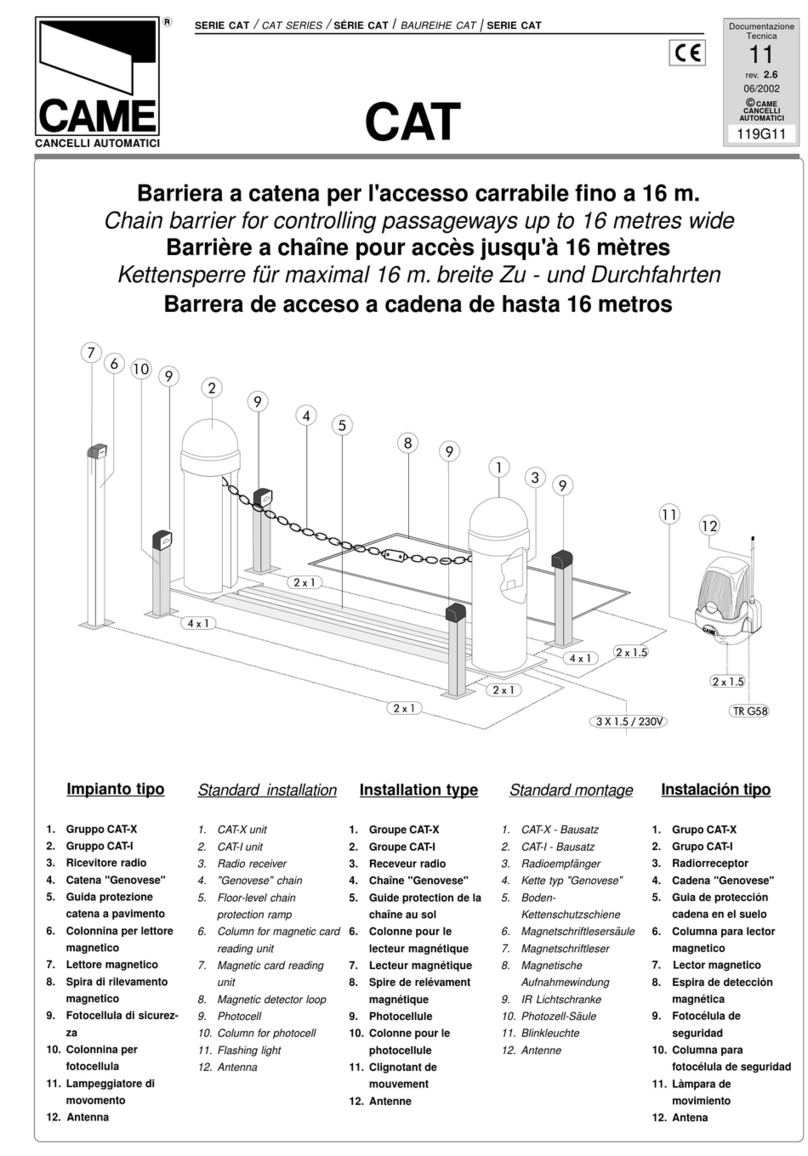
CAME CAT Series User manual

CAME
CAME G4040EZT User manual

CAME
CAME GARD 8 SERIES Owner's manual

CAME
CAME AF43SR User manual

CAME
CAME 803XA-0600 User manual

CAME
CAME GLT40AOS User manual

CAME
CAME GARD 8 SERIES User manual

CAME
CAME RBM84-HW User manual

CAME
CAME CAT Series User manual

CAME
CAME GARD 8 SERIES User manual