Camsat CAM-Analog2.0 User manual

CAM-Analog2.0
CVI/TVI/AHD
User manual
ver. 1.1
Wireless signal transmission kit or analog CVI, TVI and
AHD CCTV cameras with resolution up to 2Mpix

Thank you for choosing our product. We are sure that you will appreciate its unique
features. Please read the manual to ensure safe use and enable maximum performance.
Table o contents
Sa ety and maintenance tips. .............................................................................................. 2
R&TTE declaration o con ormity ......................................................................................... 3
Basic in ormation ................................................................................................................. 4
Package contents: ................................................................................................................ 5
Technical parameters: .......................................................................................................... 5
First start .............................................................................................................................. 6
Be ore you begin .................................................................................................................. 6
Working channel settings (dipswitch CHANNEL) ................................................................ 7
Setting up the radio power (dipswitch SETTINGS – 5) ........................................................ 7
Setting up working mode (dipswitch SETTINGS - 6) ........................................................... 7
Installation ........................................................................................................................... 7
Description o indicators and joints ..................................................................................... 8
Recommendations ............................................................................................................... 9
Sa ety warnings .................................................................................................................... 9
General warranty terms ..................................................................................................... 10
Declaration o con ormity .................................................................................................. 10
Device disposal .................................................................................................................. 12

1. Sa ety and maintenance tips.
In order to safely use our device, you should read and observe the tips contained in this in
struction manual.
The devices do not need additional maintenance actions. We recommend
placing them on reliable construction and lying cables in that way to avoid
accidental damage and to avoid entering water into the device.
This device has been designed and manufactured with the utmost care for the safety of its
installers and users. For safety reason, observe all the guidelines in this manual and pe
ripheral devices’ manuals, such as the PC,IP camera, NVR recorder. Before installing the
devices, carefully read the entire instruction manual.
Ensure safe working conditions. The user’s own modifications of the device will prevent its
legal use and render the warranty null and void. The devices have passed through the
mandatory compliance assessment and its basic requirements in the European New Ap
proach Directives. The product is CE marked.
The device is suitable for use in the European Union and beyond. It is necessary to comply
with laws and regulations of the country. The device can work with power and on the fre
quencies forbidden in some countries.
It is necessary to comply with current norms and safety standards in current location and
on current site. Both user and installer are obliged to check the current norms and condi
tions of specific installation every time. In case non compliance of norms with current
safety requirements please refrain from installing the devices.
CAM-Analog2.0 Instrukcja
3

2. R&TTE declaration o con ormity
This device meets requirements of the European directive on radio equipment, telecommu
nication terminals as well as on their mutual identification and compatibility (Directive
1999/5/CE of the European Parliament and the Council of Europe, march 1999, on radio
equipment and telecommunication terminal equipment and the mutual recognition of their
conformity).
CAM Analog2.0 is compliant with provisions related to the safety in using electrical de
vices. Observe the following guidelines:
•the power outlet must be grounded in compliance with applicable provisions,
•before transferring the device or performing any other technical operations, discon
nect the power supply,
•do not use any damaged or worn power supply cables, as the pose a threat to the
user’s safety,
•installation works must be performed by sufficiently qualified technicians,
•do not use the device on locations where flammable substances are kept,
•secure the device so that children or unauthorized persons should not have access to
it, make certain that the device has been reliably mounted,
•the device is off only after disconnecting its power supply cables and the cables be
tween it and other devices,
•if the device is transferred to a room where the temperature is higher than where it
has been previously kept, water vapour may condensate inside its casing which will
prevent its proper use (wait until the condensed water evaporates).
Distances and interferences
1. The transmission distance may vary, depending on the frequency,
environment, radio waves, buildings, weather conditions, etc.
2. When the transmitter is near such equipment as the TV set, R LAN
wireless network, another transmitter, or when it is placed between
other radio devices, then the video stream may be interrupted or the
devices might even lose the connection. If this occurs, increase the
distance between the interrupted devices and the transmitter.
3. The signal reception may vary, depending on the transmitter’s
working height and angle. If the signal reception is not stable,
optimise the antenna settings.
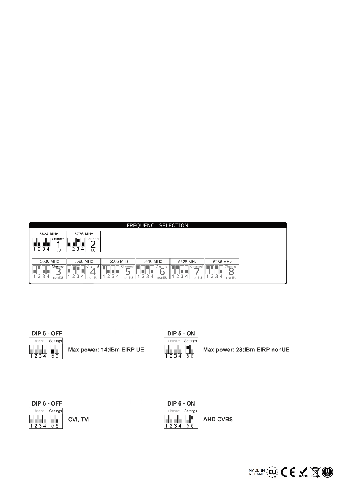
4. Meteorological radars operating withing the frequency ranges of
5.250 5.350MHz and 5.650 5.850MHz have the highest priority.
These radars can interrupt the device operation or prevent it entirely.
Warning
The antennas used for transmission from this transmitter must be installed
according to the instruction manual and they must be placed at least 30cm
from all persons. The transmitter is not compatible with another antenna
nor transmitter.
CAM-Analog2.0 Instrukcja
4

3. Basic in ormation
The kit is intended for wireless transmission of an HD TVI, HD CVI and AHD signal through
a radio link in the ISM 5.8GHz band. It supports 2 channels in the CE frequencies ranging
from 5725MHz and 5825MHz, and additional 4 channels in the frequencies from 5200MHz
to 5875MHZ intended for operation in some non EU countries.
The system enables camera image transmission in the following standards:
•HD TVI 2.0Mpix (1080p and below)
•HD CVI 2Mpix (1080p and below)
•AHD 2.0 Mpix (1080p and below)
•CVBS in the PAL/NTSC standard.
The system has surge protectors and anti interference protection built in. It guarantees in
put socket protected from damage and interference through wires.
Transmitter has:
•BNC 75ohm video input for cameras’ signal
•DC power socket
•DIPswitch for setting up channels and working parameters
Receiver has:
•BNC 75ohm video output for camera’s signal
•DC power socket
•DIPswitch for setting up channels and working parameters
a) Package contents:
•Transmitter video/audio with built in directional antenna
•Receiver video/audio with built in directional antenna
•U bolt or zip ties
•User manual
CAM-Analog2.0 Instrukcja
5

b) Technical parameters:
Video standard
TVI (TurboHD, Hikvision), CVI (Dahua, BCS)
AHD; Resulution up to 2Mpix
Range over 500 m
CE Frequencies / Frequencies for some non
UE countries
from 5725 MHz to 5875 MHz / from 5200 MHz
to 5875 MHz
Width of the working channel 20 / 40Mhz
Number of working channels: all/CE UE 6 / 2
Transmitting power
25 mW (14 dBm) maximal power permitted in
the EU (CE)
Antenna
Built in directional antenna, with working angle
45°
Audio No
OSD controls No
Video BNC 1Vp p (75 Ω)
Receiver sensitivity 85 dBm
Modulation Analog FM
Power supply
Transmitter: 9 16V DC / 800mA Receiver: 9 16V
DC / 500mA
Mounting Zip ties or u bolt
Working temperature 20°C ÷ 55°C
Dimensions Tx: 152x105x60 [mm], Rx: 164x164x80 [mm]
Use Outdoor IP66
Guarantee 2 years
Norms compliance CE, RoHS
CAM-Analog2.0 Instrukcja
6

4. First start
a) Be ore you begin
•Before you proceed to install the unit on the mast you need to:
◦check if the device has not been damaged during transport,
◦select the right location for installation to ensure full line of sight of the antennas;
materials and obstructions such as glass, a tree or walls cause significant attenu
ation of the signal and transmission interference,
◦it is recommended to install the device 3 meters above the highest obstruction in
the transmission route;
◦receiver and transmitter should be installed at long distance from other radio de
vices; the recommended minimal distance is 6m,
◦check the channel settings (dipswitch CHANNEL): transmitter and receiver must
be set to the same channel; if the settings are not the same, please select them as
specified in the table below.
b) Working channel settings (dipswitch CHANNEL)
In the EU countries you should use channels 1 and 2. Other channels are intended to use
in some non EU countries.
c) Setting up the radio power (dipswitch SETTINGS – 5)
Configure the radio power referring to current laws in the installation region using switch
SETTINGS nr 5. For most UE countries 14dBm in 5.8GHz is the maximal signal strength.
d) Setting up working mode (dipswitch SETTINGS - 6)
Configure the format of video signal using SETTINGS – 6 switch referring to camera stan
dard.
CAM-Analog2.0 Instrukcja
7

e) Installation
Mount the device to the pole in such way to direct the antenna directly into receiver
location. Attention: Transmitter’s antenna need to have clear line of sight with receiver’s
antenna (example of installation is shown below).
Connect the video signal cables to the BNC socket.
The length of the coaxial cable with video signal should not exceed 50m.
Attention: use only high quality 75Ω coaxial cables, for example RG6.
Using UTP 100Ω cables it is necessary to use high quality matching
transformer (Balum) Remember that every transformer or its passive video
converter cause video signal loss. With signal loss through the air, the level
of the signal may be visibly lowered.
Set up the working channel. Antennas polarisation (vertical installation) and the number of
the channel should be the same in both cooperating devices.
Nadajnik odbiornik
WARNING
To ensure stable radio range, the antennas need to have clear line of sight.
It is necessary to ensure full optical visibility in the first Fresnel zone. With
5.8GHz frequency and 400m distance you need to ensure at least free 3.2m
radius of space (r in the dr point) for radio beam.
CAM-Analog2.0 Instrukcja
8

) Description o indicators and joints
LED POWER indicator – lights up to indicate connected power
MODE indicator – type of video standard – lights up to indicate detected video signal in CVI
or TVI standard; only in the transmitter.
g) Recommendations
1. The system works in analog FM standard and may be exposed on interference
caused by other radio systems. Before the installation check the occupancy of 5GHz
band in the vicinity of the installation.
2. Larger systems containing a few sets should be launched and set in sequence, i.e.
connect the next set only after precise configuration and launching previous set.
3. Due to generating interferences it is not recommended use of cheap switch mode
power supplies and other power supplies than intended to use, for example CAMSAT
ZS12/1A.
4. It is not recommended to connect transmitter with receiver to one shared power
supply. It is possible to use one power supply with few receivers and another power
supply with few transmitters.
5. It is recommended to install the transmitters at the distance of 6 7m from other
wireless systems like GSM or Wi Fi.
6. High quality coaxial cables should be used.
CAM-Analog2.0 Instrukcja
9

5. Sa ety warnings
5.1. General warranty terms
The device is supplied with a standard warranty card. The manufacturer declines all other
warranties. In no case the producer is liable for any damages (including, without limita
tion, consequential, special, or incidental damages, or damage for loss of profits, business
interruption, loss of business information or other pecuniary loss) arising out of the use or
inability to use this product, even if the manufacturer has been advised of the possibility of
such damages.
Camsat grants a 24 month warranty for the CAM Analog2.0 transmission kit
1. If the device is not be operating properly, make sure, before returning the device for ser
vicing, that everything was done according to the operating manual.
2. If the faulty device is returned or send in for repairs, a thorough written description of
the signs of the device’s faulty operation, including the operating environment and the
manner in which they appear, should be enclosed.
3. The prerequisite for exercising the warranty rights is enclosing the proof of purchase, in
cluding the purchase date and description of damage, with faulty device.
4. Warranty repairs cover only faults occurring due to reasons inherent to the sold device.
5. Warranty repairs will be carried out in the shortest possible amount of time not exceed
ing 14 days, counting from the moment of accepting the device for servicing. If parts need
to be imported, the repair deadline may be extended by the repair time.
6. The warrantor is not responsible for the loss of the device configuration settings result
ing from device repair or malfunction.
7. The warrantor may refuse to carry out warranty repairs or terminate the warranty if it is
determined that the seals placed on devices or components comprising it are damaged.
8. All repair services resulting from warranty are made exclusively in the Camsat service.
Warranty does not cover
1. Mechanical damage of devices and failures occurring due to fortuitous events, such as:
fire, power grid overvoltage, electrical discharges, power supply, effects of chemical sub
stances.
2. Damage occurring due to: improper handling of the device, using the device against its
intended use or the operating manual, customer’s negligence, improper use (temperature,
humidity, flooding, dust, sanding up, improper supply voltage).
3. Claims on account of the technical parameters, if they are consistent with those indi
cated by the manufacturer.
CAM-Analog2.0 Instrukcja
10

5.2. Declaration o con ormity
CAM-Analog2.0 Instrukcja
11

Hereby, CAMSAT Gralak Przemysław declares that the product series CAM Analog2.0
meets the essential requirements and other relevant provisions of Directive 1999/5/WE.
The device is CE marked, which indicates compliance with the guidelines of the Directive.
The device can be sold and used for transmission in the 5GHz band. The frequency range
can be adjusted using the settings in accordance with legal regulations in every country.
It is your responsibility to be adequate settings of the complying with the applicable laws
in the country or region.
5.3. Device disposal
The mark presented to the left informs that this electrical or electronic
device, after its use has ended, cannot be thrown together with house
hold refuse. The device should be delivered to a specialised collection
point. Detailed information about the closest collection point is avail
able from local authorities.
The proper disposal of this device allows for preserving precious resources and avoiding
the negative impact on health and environment, which may be endangered if the waste is
handled improperly. Importer waste disposal is subject to penalties provided for in the
appropriate regulations.
Manufacturer:
CAMSAT
Ogrodowa 2a
86 050 Solec Kujawski
Poland
Offer and information: www.camsat.com.pl
Service: [email protected]om.pl
Technical support
tel. + 48 505 272 224
CAM-Analog2.0 Manual
Table of contents
Other Camsat Transmitter manuals

Camsat
Camsat CDS-6IP SMA User manual

Camsat
Camsat CAM8h-Multi2/AHD User manual

Camsat
Camsat CDS-5IPmini Operator's manual

Camsat
Camsat CDS-6IPeco Operator's manual

Camsat
Camsat CDS-6IP MULTI POE User manual

Camsat
Camsat CAM8h-AHD User manual

Camsat
Camsat TCO 5807m User manual

Camsat
Camsat CAM-9 User manual

Camsat
Camsat GlobalCAM-LTE User manual

Camsat
Camsat TCO-7h Plus User manual