Camsat CDS-6IP 3PoE User manual

Thank you for choosing the CDS-6IP PoE. We trust that its unique features will come in
ery handy. Please, read this manual to ensure safe operation and maximise efficiency
of the de ice.
The contents of this manual comprise proprietary information of CAMSAT and are intended
only for use by purchasers of the equipment described herein.
In order to copy or use any part of this manual for purposes other than the application or
maintenance of the described equipment, it is required that the customer should first
obtain a written consent from CAMSAT.

Table of Contents
I Safety and maintenan e tips...................................................................................................4
1. Safety tips.............................................................................................................................. 4
2. R&TTE declaration of conformity...........................................................................................5
3. Distances and interferences..................................................................................................5
II CDS-6IP 3PoE.........................................................................................................................6
1. IP cameras bitrate................................................................................................................. 6
2. PoE ports................................................................................................................................ 6
3. Power supply.......................................................................................................................... 6
4. Contents of the package........................................................................................................ 7
5. Description of the connectors................................................................................................ 8
6. Some connection options with IP cameras...........................................................................9
III System onfiguration.........................................................................................................12
1. First system start-up........................................................................................................... 12
2. WWW panel.......................................................................................................................... 13
3. Mounting the de ice on site................................................................................................14
4. Launching the de ice........................................................................................................... 14
5. Logging in............................................................................................................................ 15
6. Setting up IP address.......................................................................................................... 15
7. Scanning the usage of operating channels.........................................................................16
8. Operating mode settings (transmitter / recei er)..............................................................17
9. SSID radio link name........................................................................................................... 17
10. Distance............................................................................................................................. 18
11. Wireless transmission testing...........................................................................................18
12. Password changing............................................................................................................19
13. Connection testing with PING command..........................................................................19
14. Security of radio connection.............................................................................................20
15. The list of a ailable frequencies........................................................................................20
16. Test and installation tools................................................................................................. 21
17. Troubleshooting................................................................................................................. 22
IV Appendix A..........................................................................................................................23
V General warranty terms........................................................................................................24
VI Devi e disposal....................................................................................................................26
3

I Safety and maintenan e tips
In order to safely use our de ice, you should read and obser e the tips contained in this
manual.
CDS-6IP 3PoE module is maintenance-free. We recommend installing it on a
stable structure and connecting its power cables in a manner that would
pre ent them from being accidentally damaged by the operator or any
bystanders.
1. Safety tips
This de ice has been designed and manufactured with the utmost care for the safety of
its installers and users. For safety reasons, obser e all the guidelines in this manual and
peripheral de ices’ manuals, such as the PC or IP camera. Before installing the de ice,
carefully read the entire manual, especially the part regarding safety.
Ensure safe working conditions. The user’s own modifications of the de ice will pre ent
its legal use and render the warranty null and oid. The de ice has passed through the
mandatory compliance assessment and it meets basic requirements in the European New
Approach Directi es. The product is CE-marked.
The de ice is suitable for use in the European Union and beyond. You must comply with
the laws and regulations in force in your country. The de ice has the ability to work with
power and frequency not allowed in your country.
WARNING: You should not be present at a distance smaller than 30 m from the radio
devi e working.
4

2. R&TTE de laration of onformity
This de ice meets requirements of the European directi e on radio equipment, telecom-
munications terminals as well as on their mutual identification and compatibility (RED:
2014/53/UE).
CDS-6IP 3PoE module is compliant with pro isions related to the safety in using electri-
cal de ices. Obser e the following guidelines:
•the power outlet must be earthed in compliance with applicable pro isions,
•before transferring the de ice or performing any other technical operations, di-
sconnect the power supply,
•do not use any damaged or worn power supply cables, as they pose a threat to the
user’s safety,
•installation works must be performed by sufficiently qualified technicians,
•do not use the de ice in locations where flammable substances are kept,
•secure the de ice so that children or unauthorized persons should not gain access
to it, make sure that the de ice has been reliably fixed,
•the de ice is off only after disconnecting its power supply cables and the cables
between it and other de ices,
•if the de ice is transferred to a room where the temperature is higher than where it
has pre iously been kept, water apor may condensate inside its casing, which will
pre ent its proper use (in that case, wait until the condensed water e aporates).
3. Distan es and interferen es
•The transmission distance may ary, depending on the frequency, en ironment, ra-
dio wa es, buildings, weather conditions, etc.
•When the transmitter is near such equipment as the TV set, R-LAN wireless ne-
twork, another transmitter, or when it is placed between other radio de ices, then
the ideo stream may be interrupted or the de ices might e en lose the connec-
tion. If this occurs, increase the distance between the interrupting de ices and the
transmitter.
•The signal reception may ary, depending on the transmitter’s working height and
angle. If the signal reception is not stable, optimize the antenna settings.
•Meteorological radars operating within the frequency ranges of 5,250-5,350MHz
and 5,650-5,850MHz ha e the highest priority. These radars can interrupt the de-
ice operation or e en pre ent it entirely.
The antennas used for the transmission from this transmitter must be installed
according to the manual and they must be placed at least 30cm from all
persons.
5
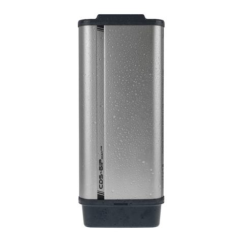
II CDS-6IP 3PoE
A system with 3 PoE ports, for wireless transmission of video and audio from IP ameras.
The CDS-6IP 3PoE radio unit is designed for two-way transmission of all data between IP
cameras and the IP network in which the recorder or VSM ideo recording system is located.
The de ice is adapted to work with the cameras with resolution up to 16Mpix and 63Mbps
bitrate.
The CDS-6IP 3PoE is a two-unit that transparently transmits all data between networks. It is
not necessary to assign the same family of IP addresses as in the camera. Abo e all, radio
de ices that communicate wirelessly must ha e the same addressing family.
1. IP ameras bitrate
The unit guarantees continuous and stable transmission capacity of up to 63Mbps bitrate and
pro ides wireless connecti ity o er a distance of up to 2km according to this specification:
• 63Mbps bitrate – 100m,
• 60Mbps bitrate – 500m,
• 48Mbps bitrate – 1000m,
• 33Mbps bitrate – 1500m,
• 12Mbps bitrate – 2000m.
2. PoE ports
The de ice has three RJ45 10/10 Ethernet ports with PoE+ function. PoE ports are acti e
when supplying the unit with 48V DC, PoE48 PSU or PoE switch.
3. Power supply
48V DC – Due to the highest current efficiency, we recommend using a 48V DC power supply
with a minimum capacity of 2A. If the unit is powered by a 48V DC/2A power supply, the
efficiency of each PoE port is 30W.
It is also possible to power the radio unit directly from the PoE switch or PoE adapter that is
included in the set.
Powering the devi e from the PoE swit h or PoE power supply - RJ45 LAN port has double
functionality. It can work as an input for a PoE power supply and can be a port for connecting
and powering an IP camera with PoE. The functionality of this port changes automatically
when a PoE adapter or PoE switch connection is detected. Please remember that the current
efficiency of such a system is limited to the maximum efficiency of the switch or connected
PoE power supply. PoE switches ha e a capacity of about 15W or 30W depending on the
standard used (802.3af, 802.3at).
6

The PoE48V/0.5A power supply, in luded in the set – The 24W PoE48 power supply which is
included in each set pro ides power for the radio unit itself which consumes up 8W of power
and for one or two IP cameras with current consumption which should not exceed 15W in
total.
Power supply from 12V to 24V DC - DC if it is not necessary to use PoE, it is possible to power
the radio unit itself with low oltage 12-24V DC. This is ery helpful when using battery, car or
low oltage buffer power supplies.
Point-to-Point and Point-to-Multipoint – works in both Point-to-Point and Point-to-Multipoint
configuration, which allows collecting signals from many distributed transmitters and enables
efficient connection of two IP networks in the BRIDGE mode.
Maximum CE power allowed by law in Europe – output power: 27dBm (500mW).
5GHz – stable radio band with 16 operating frequencies that allows you to create a network
with more than 100 IP cameras.
Transmission en oding – transmission secured by 64/128-bit code and the newest WPA-
PSK2 encoding.
2km LOS range – the built-in dual MIMO 5GHz 2 x 14dbi antenna pro ides a stable range up to
2000m. 5GHz high-frequency band requires the correct optical isibility of the so-called LOS
antennas. If there are obstacles along the way, the wireless range will be significantly reduced
– Fresnel Zone.
Housing protecting the entire installation against external weather conditions with IP55
tightness class. Working temperature: from -20°C to +70°C.
iCAMSAT – ideo communication protocol, guaranteeing stable and uninterrupted
transmission of nearly 100% of frames.
36 months of warranty – peace and full technical support for years.
4. Contents of the pa kage
•CDS-6IP 3PoE x 1
•PoE48V 0.5A power supply with 230V European or UK adapter x 1
•Clamping grip to mount the de ice on the pole x 2szt
•User’s manual and CE Declaration of Conformity
7

5. Des ription of the onne tors
CONNECTORS
PORT 1 - Dual-function LAN port (RJ45) which has an input for a PoE power supply or an output for
powering a PoE IP camera.
PORT 2 & PORT 3 - LAN ports with PoE to power IP cameras or power another CDS-6IP 3PoE radio
unit.
Power strip – triple electric strip for connecting electric wires with cross section up to 1,0mm2. with:
•Clip 1 is a place to connect a +48V power.
•Clip 2 (middle) is used to connect the minus (GND – ommon to all voltages)
•Clip 3 is a place to connect a +12-24V DC power. WARNING – Do not onne t voltage
above 30V here. This will permanently damage the devi e.
RESET – button for resetting the radio module to the default settings. Press and hold for a minimum
of 5 seconds to reset the settings.
8

6. Some onne tion options with IP ameras
9

10

11

III System onfiguration
1. First system start-up
IMPORTANT: It is recommended to make first start and configuration of the system du-
ring dry run. Mount the de ices on the site only after a full radio connection.
To start and onfigure a radio devi e connect the CDS-6IP 3PoE to the power supply. Use one
of 4 power options:
•PoE48V/0,5A power supply that is included in the set – connect to the port 1 with UPT
cable (length up to 50m).
•Swit h PoE – connect UTP cable to any PoE switch with 802.3at or 802.3af support.
After few seconds switch will recognize the standard and turn on powering the radio
unit. When connecting PoE cameras to ports 2 and 3, please take into account the
maximum camera power which cannot exceed 15W in total.
•48V DC power supply – the best power source when connecting se eral PoE IP
cameras to ports 1, 2, 3.
•Power supply from 12V to 24V DC – low oltage power supply is reser ed only to power
the radio module itself and this power option will not supply power to the PoE ports.
Conne t the omputer to the radio unit using a straight (not crosso er) UTP cable. All 3 ports
in the radio unit are used for communication with the computer. You can also use the LAN port
on the PoE power supply.
To onfigure the devi e, use any web browser on the computer or mobile de ice.
12

To log into the CDS-6IP 3PoE wireless module, set the computer’s IP address in the same IP
subnet (the radio unit’s default IP address in 192.168.1.1). Then start the web browser and
enter the IP address of the radio unit. The login menu will appear on the s reen:
When using the IE browser, due to the lack of manufacturer’s support for this browser,
some web content may not display properly. In this case, please delete in IE browser
„browsing history” together with cookies ( ools / Delete browser history or Ctrl+Shift+Del).
In the abo e screen, enter your login details (default alues: Username: camsat,
Password: camsat), then click the Login button to log in to the module.
2. WWW panel
LINK INFORMATION
•LAN Status – basic information about the IP radio module settings.
•Wireless Status – list of acti e wireless connections, along with information about the
connection quality of the IP modules.
•Devi e Info – information about this IP module.
CAMERA CONNECTION SETTINGS
Wireless
•Wireless Settings – setting up working mode - Master (recei er) / Sla e
(transmitter), encoding settings of transmission.
•WAN Settings – mode settings of the wireless link, e.g. Video Bridge.
•Wireless Advan ed Settings – the configuration of the wireless link, e.g. channel
number, distance, region, the strength of the signal.
Network Settings
•LAN Settings – setting up IP address, subnet mask, gate.
13

ADVANCED SETTINGS
•Time Zone Setting – Set the time of the NTP ser er.
•System Log – a re iew of recent work and changes in the CDS-6IP 3PoE de ice.
•Upgrade Firmware – update software.
•Ba kup/Restore – sa e/restore the system configuration.
•Password – change the password.
•Dual Slave – adding a second connection to another Master, e.g. to create a
connection ser ice network.
•Multi Masters – adding additional radio links with a different SSID, for example
ser ice connection, the second stream ideo, test, etc.
•Servi es – automation and ser ice tools.
3. Mounting the devi e on site
Fo mounting on the pole, use the cable ties included in the kit. These are special bands
designed for external atmospheric conditions and resistant to UV radiation.
While installing units on outdoor poles, make sure to use overvoltage prote tion for Ethernet ables.
The pole must be earthed un onditionally. Failure to follow these guidelines may result in damaging
the equipment during lightning strikes. This type of damage is not overed by the warranty.
4. Laun hing the devi e
Configuration of CDS-6IP 3PoE modules should be carried out in turn, starting from the
recei ing point, i.e. the recorder side (MASTER operating mode). It is recommended to
configure the de ices in dry run (without hanging the de ices on the site). Before setting up
the radio system, you must first configure the IP camera, install it on your computer and check
the correct reception of the image.
a) Knowing the IP addresses of cameras and the address of the CDS-6IP 3PoE module,
set the computer’s IP address in such a way that all de ices work in one subnet (IP
addresses in the range 192.168.1.2 – 192.168.1.254 are recommended). It is not
allowed to set two identical addresses in one local network.
b) Launch a web browser (e.g. Internet Explorer). In the address bar, enter the IP
address of the CDS-6IP 3PoE de ice (by default 192.168.1.1). The login panel should
appear on the screen.
If the browser returns an error or a page is missing, make sure that our network card has a
fixed (not DHCP) IP address from the subnet 1 2.168.1.x.
If the de ice with the address 192.168.1.1 is already working in the local network, it should be
disconnected for the time of configuration in order to a oid conflicts of IP addresses. You can
also temporarily disconnect your computer from the local network.
14

5. Logging in
To log in to the network interface, the user must enter a user name and password (default:
Username: camsat, Password: camsat) and confirm with a Login button. It will be included in
the management interface of CDS-6IP 3PoE module.
Warning! Any remote hanges in the radio link settings, after installing the units on the poles,
starting from the transmitting side. Otherwise, after a hange in the re eiving unit (e.g. working
hannel), we ould lose onne tion with the transmitting units and thus we would lose the possibility
of remote re onfiguration.
REALLY USEFUL: CDS-6IP 3PoE has a spe ial fun tion of testing the onne tion after hanging the settings. If
you do not a ept the displayed message, the unit will return to its previous settings.
6. Setting up IP address
First, configure the LAN network parameters. Go to menu CAMERA CONNECTION SETTINGS
→ Network Settings. The following screen will appear:
Enter the new IP address for the CDS-6IP 3PoE (IP Address field) (IP address must be on the
same subnet as the computer), subnet mask, IP address of the gateway (Default Gateway)
(entering the IP address of the gateway is only necessary if the de ice operates outside the
local network). Remember to set a unique IP address for the local network (each CDS-6IP
3PoE must ha e a unique IP address). Subnet mask and gateway must be identical throughout
the network. Confirm changes with the Save Changes button.
The devi e an reset itself automati ally and then you will need to log in again.
15

7. S anning the usage of operating hannels
The CDS-6IP 3PoE modules allow scanning the ether for frequencies used
nearby. It is a ery useful tool when setting up the working channel. With it, we
know which channels to a oid and which are free and can be used for wireless
transmission of signals from the IP cameras. Using a channel that is already occupied by other
transmission lines may result in interference or no transmission at all.
To scan channels, temporarily switch unit to SLAVE mode (Cameras). To do this, go to the
menu CAMERA CONNECTION SETTINGS → Wireless Settings and select the Sla e (Cameras)
parameter. Confirm with the Sa e Changes button.
Click the SCAN MASTERS button to begin scanning automatically. After a while, the list of
frequencies used in the area will be displayed together with the strength of their signals. The
signals below -85 and that kind of frequencies, alongside with channels not listed, may be
used for wireless ideo transmission.
Warning
Do not use the AUTO hannel settings. Be sure to sele t the hannel number permanently a ording
to the urrent network bandwidth onsumption.
16

8. Operating mode settings (transmitter / re eiver)
The next step is to configure the basic parameters of the radio connection to be set
in the menu CAMERA CONNECTION SETTINGS → Wireless.
WAN Connection Type in the WAN Settings tab should remain set to VIDEO BRIDGE – it is the
default option recommended for use with IP cameras. Next, select the operating Mode in the
Wireless Settings tab:
MASTER (NVR/DVR) – for the collection point, (unit connected to the recorder).
SLAVE (Cameras) – for broadcasting points (connected to the IP cameras).
Important: Set up the frequen y hannels taking into a ount information from point 15 of hapter
III of this manual.
9. SSID radio link name
(Required only for subsequent re eivers)
To ensure communication between the CDS-6IP 3POE wireless modules, all units must use the
same SSID (set it in the Wireless Settings tab, Link Name (SSID) parameter). When setting up
the SLAVE (Cameras) modules you can search for already working MASTER (NVR/DVR)
modules using the SCAN MASTERS option and select the module with which you want to
connect to from the list.
The changes must be confirmed by pressing the Save Changes button.
The SSID must be unique for ea h re eiver on the site.
17

10. Distan e
Another important parameter to declare is the distance between transmitter and
recei er. In the menu CAMERA CONNECTION SETTINGS → Wireless, under the
Wireless Advan ed Settings tab, change the Distance parameter by entering the
actual distance on kilometers.
When configuring the MASTER unit (NVR/DVR), you must select the frequency of the radio link
(Channel). By default. the de ice is set to automatic channel selection (DFS) but it is ad isable
to select a free, not used by other users operating channel. Confirm the change by clicking the
Save Changes button. Before setting up the operating channel it is recommended to scan the
radio frequency to check the busy channels. See chapter III, point 7.
11. Wireless transmission testing
The last step is to check the correctness of transmission between de ices. To
check the information about connected CDS-6IP 3PoE de ices such as MAC
address, signal strength, connection time, IP address, etc., go to the Link Status.
Basic information about the wireless connection will appear in the Wireless Status
tab. Additionally, in the unit working in the MASTER (NVR/DVR) mode, the Wireless Clients
tab will display a list of CDS-6IP 3PoE wireless units connected to this module.
18

12. Password hanging
Go to the ADVANCED SETTINGS → Password and change the default password to
your own to pre ent the possibility to log into the de ice by unauthorized persons.
In the New Password field, enter the new password and confirm it in the Confirm
Password field. Confirm the change by Save Changes button.
13. Conne tion testing with PING ommand
To erify the configuration of the de ices, connection parameters, and connection
stability when mounted on a site, you can run a test using the PING command
(enter the command into Windows’ command line).
In order to run the command line in Windows, click on Start → Run (on newer systems, type
CMD).
In the console, enter the command ping 192.168.1.1 and press Enter.
Example ommand
Chacking if your computer can communicate with the CDS-6IP 3PoE de ice with assigned
address 192.168.1.1 (the 192.168.1.1 IP address is assigned by default to each new CDS-6IP
3PoE de ice).
In the console, enter the command ping 192.168.1.1 and press Enter.
Example of returned message:
Reply from 192.168.1.1: bytes=32 time<1 ms TTL=64
If the response time of the de ice is shorter than 200-400ms it means that configuration is
correct.
To make sure that all de ices are correctly configured, you can execute the command PING
with the address of each de ice in the system (CDS-6IP 3PoE, IP cameras, routers, recorders).
19

14. Se urity of radio onne tion
The CDS-6IP 3PoE de ices ha e the option of secure ideo transmission with an
encryption key or such algorithms as WPA-PSK and WPA-PSK2.
To secure the transmission, select the CAMERA CONNECTION SETTINGS →
Wireless Settings. From the drop-down menu, select the Authentication method
Security
•Open: This option enables connecting to any de ice without any protection measures.
The wireless onne tion is not en oded if this option is hosen.
•WPA-PSK: This is the simplified WPA mode, which does not need any special ser er for
authentication. Instead, it uses the WPA network key, pre-determined for e ery radio
link node. This is an efficient solution for big and medium-sized stationary structures.
•WPA-PSK2: It is the new WPA ersion; only clients with the WPA2 are a ailable. If this
option is selected, the data will be encrypted with the AES algorithm and a password
will be required for communication.
If the WPA data encryption method is selected, a network key is required, the same for all
CDS-6IP 3PoE units. User can select the encryption key type in the Data Encryption menu:
64-bit WEP: consists of no more than 10 hexadecimal characters.
128-bit WEP: consists of no more than 26 hexadecimal characters.
15. The list of available frequen ies
(for the default hannel width of 40MHz).
Regulation Range (intended use) Channel number Channel frequen y
ETSI (European Union) 5,15~5,25GHz
(indoor)
36 5180
44 5220
5,25~5,35GHz
(indoor)
52 5260
60 5300
5,50~5,70GHz
(outdoor)
100 5500
108 5540
116 5580
124 5620
136 5680
Use the respecti e channels according to their intended purpose:
•indoor – only inside buildings,
•outdoor – only outside buildings.
Selecting other frequencies depends on legal regulation applicable in the country of use. If not
sure what regulations are applicable in the country of use, consult with the CDS-6IP 3PoE
module seller.
20
Table of contents
Other Camsat Transmitter manuals

Camsat
Camsat CAM8h-AHD User manual

Camsat
Camsat TCO 5807m User manual

Camsat
Camsat CDS-6IP SMA User manual

Camsat
Camsat TCO-7h Plus User manual

Camsat
Camsat CDS-6IPeco Operator's manual

Camsat
Camsat CDS-6IP MULTI POE User manual

Camsat
Camsat CDS-LIFT IP User manual

Camsat
Camsat CDS-5IPmini Operator's manual

Camsat
Camsat GlobalCAM-LTE User manual

Camsat
Camsat CAM-Analog2.0 User manual
Popular Transmitter manuals by other brands

Emerson
Emerson Rosemount 3051 quick start guide

ATEN
ATEN VE2812T user manual

EUTECH INSTRUMENTS
EUTECH INSTRUMENTS ALPHA PH1000 PHORP CONTROLLERTRANSMITTER Instructions d'utilisation

MSA
MSA General Monitors S4100T instruction manual

Aukey
Aukey BT-F4 user manual

Risco
Risco 4 Button Rolling Code Keyfob quick start guide