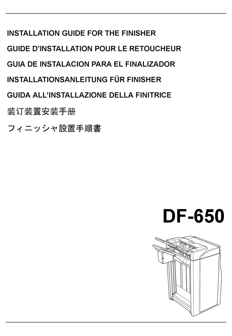
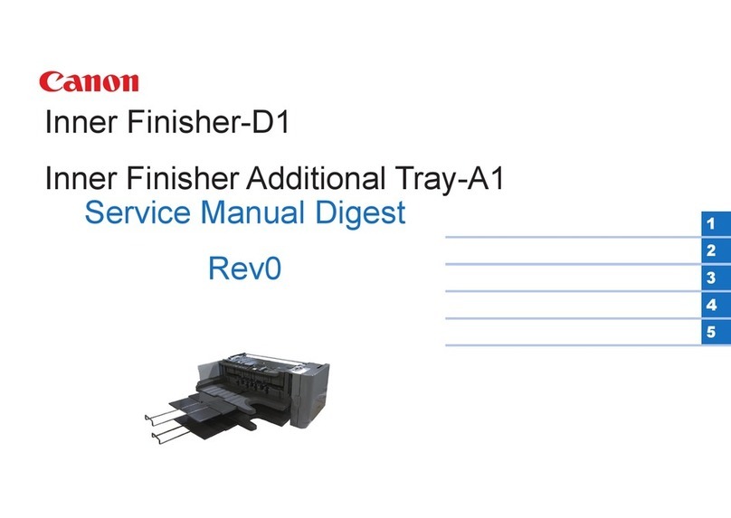
Canon Staple Finisher-D1 User manual

7654321
Product Outline
Technology
Periodic Servicing
Parts Replacement and Cleaning Procedure
Adjustment
Installation
Appendix
Staple Finisher-D1 / Booklet Finisher-D1
Service Manual
F-0-1F-0-1
May 5, 2010
Revision 0

0
00-2
0-2
Application
This manual has been issued by Canon Inc. for qualied persons to learn technical theory,
installation, maintenance, and repair of products. This manual covers all localities where the
products are sold. For this reason, there may be information in this manual that does not
apply to your locality.
Corrections
This manual may contain technical inaccuracies or typographical errors due to improvements
or changes in products. When changes occur in applicable products or in the contents of this
manual, Canon will release technical information as the need arises. In the event of major
changes in the contents of this manual over a long or short period, Canon will issue a new
edition of this manual.
The following paragraph does not apply to any countries where such provisions are
inconsistent with local law.
Trademarks
The product names and company names used in this manual are the registered trademarks
of the individual companies.
Copyright
This manual is copyrighted with all rights reserved. Under the copyright laws, this manual may
not be copied, reproduced or translated into another language, in whole or in part, without the
written consent of Canon Inc.
(C) CANON INC. 2009
Caution
Use of this manual should be strictly supervised to avoid disclosure of condential
information.

0
00-3
0-3
Explanation of Symbols
The following symbols are used throughout this Service Manual.
Symbols Explanation Symbols Explanation
Check. Remove the claw.
Check visually. Insert the claw.
Check the noise. Use the bundled part.
Disconnect the connector. Push the part.
Connect the connector. Plug the power cable.
Remove the cable/wire
from the cable guide or wire
saddle. Turn on the power.
Set the cable/wire to the
cable guide or wire saddle.
Remove the screw.
Tighten the screw.
The following rules apply throughout this Service Manual:
1. Each chapter contains sections explaining the purpose of specic functions and the
relationship between electrical and mechanical systems with reference to the timing of
operation.
In the diagrams, represents the path of mechanical drive; where a signal name
accompanies the symbol, the arrow indicates the direction of the electric
signal.
The expression "turn on the power" means ipping on the power switch, closing the
front door, and closing the delivery unit door, which results in supplying the machine with
power.
2. In the digital circuits, '1' is used to indicate that the voltage level of a given signal is
"High", while '0' is used to indicate "Low". (The voltage value, however, differs from
circuit to circuit.) In addition, the asterisk (*) as in "DRMD*" indicates that the DRMD
signal goes on when '0'.
In practically all cases, the internal mechanisms of a microprocessor cannot be checked
in the eld. Therefore, the operations of the microprocessors used in the machines
are not discussed: they are explained in terms of from sensors to the input of the DC
controller PCB and from the output of the DC controller PCB to the loads.
The descriptions in this Service Manual are subject to change without notice for product
improvement or other purposes, and major changes will be communicated in the form of
Service Information bulletins.
All service persons are expected to have a good understanding of the contents of this Service
Manual and all relevant Service Information bulletins and be able to identify and isolate faults
in the machine.

0
00-4
0-4

0
00-5
0-5
Contents
Safety Precautions
Notes Before it Works Servicing ------------------------------------------0-2
Product Outline
Features-------------------------------------------------------------------------1-2
Specications ------------------------------------------------------------------1-3
Finisher Unit------------------------------------------------------------------------- 1-3
Staple Unit --------------------------------------------------------------------------- 1-4
Saddle Stitcher Unit (Booklet Finisher-D1)---------------------------------- 1-5
Others--------------------------------------------------------------------------------- 1-6
Names of Parts----------------------------------------------------------------1-7
External View(Front) -------------------------------------------------------------- 1-7
Finisher (Staple Finisher)----------------------------------------------------------------- 1-7
Saddle Finisher (Booklet Finisher) ----------------------------------------------------- 1-7
External View(Rear)--------------------------------------------------------------- 1-8
Finisher (Staple Finisher)----------------------------------------------------------------- 1-8
Saddle Finisher (Booklet Finisher) ----------------------------------------------------- 1-8
External View(Internal) ----------------------------------------------------------- 1-9
Saddle Finisher (Booklet Finisher) ----------------------------------------------------- 1-9
Cross Section(Front)-------------------------------------------------------------1-10
Finisher (Staple Finisher)----------------------------------------------------------------1-10
Saddle Finisher (Booklet Finisher) ----------------------------------------------------1-11
Optional Construction------------------------------------------------------1-12
Technology
Basic Conguration-----------------------------------------------------------2-2
Functional Conguration -------------------------------------------------------- 2-2
Overview of Electrical Circuitry ------------------------------------------------- 2-3
Controls--------------------------------------------------------------------------2-4
Controls ------------------------------------------------------------------------------ 2-4
Feeding Unit--------------------------------------------------------------------2-5
Outline-------------------------------------------------------------------------------- 2-5
Basic Operations------------------------------------------------------------------- 2-6
Straight Path Paper Feed Operation------------------------------------------ 2-7
Processing Tray Paper Feed Operation-------------------------------------- 2-9
Buffer Path Paper Feed Operation-------------------------------------------2-10
Switching Over the Paper Path------------------------------------------------2-11
Stack Tray Unit --------------------------------------------------------------2-13
Stack Tray Operation ------------------------------------------------------------2-13
Shutter Operation-----------------------------------------------------------------2-14
Processing Tray Unit -------------------------------------------------------2-15
Outline-------------------------------------------------------------------------------2-15
Basic Operation -------------------------------------------------------------------2-16
Processing Tray Paper Stacking Operation--------------------------------2-17
Shift Operation---------------------------------------------------------------------2-18
Staple Operation------------------------------------------------------------------2-19
Stack Delivery Operation -------------------------------------------------------2-21
Swing Height Detection Control -----------------------------------------------2-21
Saddle Stitcher Unit --------------------------------------------------------2-22
Outline-------------------------------------------------------------------------------2-22
Basic Sequence of Operations------------------------------------------------2-23
Paper Feed Operation-----------------------------------------------------------2-24
Roller Guide Clearance Control-----------------------------------------------2-25
Alignment Operation -------------------------------------------------------------2-26
Staple Operation------------------------------------------------------------------2-27
Paper Folding/Delivery Operations-------------------------------------------2-28
Controller Unit----------------------------------------------------------------2-30
Outline-------------------------------------------------------------------------------2-30
Finisher Controller PCB---------------------------------------------------------2-30
Saddle Stitcher Controller PCB -----------------------------------------------2-31
Detecting Jams--------------------------------------------------------------2-32
Detecting Jams--------------------------------------------------------------------2-32
Power Supply ----------------------------------------------------------------2-34
Outline-------------------------------------------------------------------------------2-34
Protective Functions -------------------------------------------------------------2-34
Work of Service--------------------------------------------------------------2-36
When replacing the parts -------------------------------------------------------2-36

0
00-6
0-6
Periodic Servicing-----------------------------------------------------------------2-36
Upgrading---------------------------------------------------------------------------2-36
Periodic Servicing
List of Work for Scheduled Servicing ------------------------------------3-2
Parts Replacement and Cleaning Procedure
List of Parts ---------------------------------------------------------------------4-2
External / Internal Covers-------------------------------------------------------- 4-2
Main Units --------------------------------------------------------------------------- 4-4
Consumable Parts Requiring Periodic Replacementand Cleaning
Points --------------------------------------------------------------------------------- 4-4
List of Solenoid --------------------------------------------------------------------- 4-5
List of Clutchs----------------------------------------------------------------------- 4-6
List of Cooling Fans --------------------------------------------------------------- 4-6
List of Motors------------------------------------------------------------------------ 4-7
List of Sensors---------------------------------------------------------------------4-11
List of Switchs ---------------------------------------------------------------------4-14
List of PCBs ------------------------------------------------------------------------4-15
Other---------------------------------------------------------------------------------4-16
External / Internal Covers-------------------------------------------------4-17
Removing the Front Door (Finisher [Staple Finisher])-------------------4-17
Removing the Front Door (Saddle Finisher [Booklet Finisher]) -------4-17
Removing the Upper Cover (Finisher [Staple Finisher]) ----------------4-18
Removing the Upper Cover (Saddle Finisher [Booklet Finisher]) ----4-18
Removing the Rear Cover (Upper) -------------------------------------------4-19
Removing the Rear Cover (Lower) -------------------------------------------4-19
Removing the Left Inner Cover (Finisher [Staple Finisher])------------4-20
Removing the Left Inner Cover (Saddle Finisher [Booklet Finisher]) 4-20
Removing the Right Inner Cover (Finisher [Staple Finisher])----------4-21
Removing the Right Inner Cover (Saddle Finisher [Booklet Finisher])----
4-21
Removing the Saddle Stitcher Cover----------------------------------------4-22
Main Units---------------------------------------------------------------------4-23
Removing the Grate-shaped Upper Guide ---------------------------------4-23
Removing the Tray-1 unit / Tray-2 unit --------------------------------------4-24
Removing the Grate-shaped Lower Guide ---------------------------------4-26
Removing the Saddle Delivery Tray------------------------------------------4-27
Removing the Stapler Drive Unit----------------------------------------------4-28
Removing the Processing Tray Unit------------------------------------------4-30
Pull out the Saddle Unit (Service Position)---------------------------------4-32
Removing the Saddle Unit------------------------------------------------------4-34
Removing the Thrust Unit-------------------------------------------------------4-37
Consumable Parts Requiring Periodic Replacement and Cleaning
Points --------------------------------------------------------------------------4-39
Removing the Static Eliminator (Feed Guide Unit)-----------------------4-39
Removing the Shutter Torque Limiter----------------------------------------4-40
Removing the Stapler Unit------------------------------------------------------4-40
Removing the Paper Holding Torque Limiter ------------------------------4-41
Removing the Tray-1 Torque Limiter -----------------------------------------4-42
Removing the Tray-2 Torque Limiter -----------------------------------------4-43
Removing the Static Eliminators (Swing Guide Unit) --------------------4-44
Checking the position attached the Swing Guide Unit-------------------4-45
Removing the Stack Delivery Upper Roller --------------------------------4-46
Removing the Sub Guide Torque Limiter -----------------------------------4-47
Removing the Static Eliminator (Grate-shaped lower guide unit) ----4-48
Removing the Paper Holding Rubber----------------------------------------4-48
Removing the Swing Guide Open Solenoid (SL101) --------------------4-49
Removing the Torque Limiter (Tray1/2 Paper Holder) -------------------4-50
Remove the Paper Holding Rollers (Front) and (Left)-------------------4-51
Removing the Paper Holding Roller------------------------------------------4-54
Removing the Shutter Clutch (CL102)---------------------------------------4-54
Clutchs/Solenoids-----------------------------------------------------------4-55
Removing the Saddle Inlet Flapper Solenoid (SL206) ------------------4-55
Adjusting the position attached the Saddle Inlet Flapper Solenoid
(SL206) ------------------------------------------------------------------------------4-56
Motors--------------------------------------------------------------------------4-57
Removing the Paper Return Guide Roller Motor (M121)---------------4-57
Removing the Gripper Motor (M117)----------------------------------------4-58
Removing the Gripper Base Motor (M116)---------------------------------4-58
Removing the Stacking Tray Paper Retainer Motor (M114) -----------4-59
Removing the Tray Auxiliary Guide Motor (M120)------------------------4-59
0
00-7
0-7
Rear Alignment Motor (M109) -------------------------------------------------4-60
Removing the Front Alignment Motor (M108) -----------------------------4-61
Removing the Tray 1 Shift Motor (M105) -----------------------------------4-63
Removing the Tray 2 Shift Motor (M106) -----------------------------------4-64
Removing the Staple Shift Motor (M107)-----------------------------------4-65
Removing the Inlet Feed Motor (M200)-------------------------------------4-66
Removing the Processing Tray Paper Retainer Motor (M118)--------4-66
Removing the Buffer Feed Motor (M102)-----------------------------------4-67
Removing the Paper Trailing Edge Pushing Guide Motor (M113)----4-67
Removing the Feed Motor (M101)--------------------------------------------4-68
Removing the Stack Delivery Upper Motor (M104) ----------------------4-69
Removing the Stack Delivery Lower/Shutter Motor (M122)------------4-69
Removing the Swing Guide Motor (M110)----------------------------------4-70
Other Parts -------------------------------------------------------------------4-71
Removing the Alignment Roller -----------------------------------------------4-71
Removing the Thrust Plate-----------------------------------------------------4-74
Removing the Folding Rollers (Upper)/(Lower) ---------------------------4-75
Switches-----------------------------------------------------------------------4-79
Removing the Staple Safety Switch (Front/Rear) (SW102/SW104) -4-79
PCBs---------------------------------------------------------------------------4-80
Removing the Finisher Controller PCB--------------------------------------4-80
Removing the Tray 1 Motor Driver PCB-------------------------------------4-81
Removing the Tray 2 Motor Driver PCB-------------------------------------4-82
Removing the AC Noise Filter PCB ------------------------------------------4-83
Removing the Power Supply Unit---------------------------------------------4-83
Adjustment
Overview ------------------------------------------------------------------------5-2
Overview ----------------------------------------------------------------------------- 5-2
Detail Description------------------------------------------------------------------ 5-2
Major Adjustments----------------------------------------------------------------- 5-2
Basic Adjustment--------------------------------------------------------------5-3
Paper Bump Amount Adjustment at the high-accuracy punch mode- 5-3
Paper Return Roller Descension Timing Adjustment --------------------- 5-4
Stack Delivery Upper Roller Ascension Timing Adjustment ------------- 5-5
Paper Switchback Position Adjustment -------------------------------------- 5-6
Paper Return Roller Ascension (Angle) Amount Adjustment ----------- 5-7
Buffer Operation Enable/Disable Mode Setting---------------------------- 5-8
Action on parts replacement -----------------------------------------------5-9
Checking the position attached the Swing Guide Unit-------------------- 5-9
Adjusting the position attached the Saddle Inlet Flapper Solenoid
(SL206) ------------------------------------------------------------------------------5-10
Note on replacing the nisher controller PCB -----------------------------5-10
Installation
How to Utilize This Installation Procedure ------------------------------6-2
Illustrations Used in This Procedure ------------------------------------------ 6-2
Descriptions Used in This Procedure ----------------------------------------- 6-2
When Using the Contained Parts (Bundled Components in the Shipping
Carton)-------------------------------------------------------------------------------- 6-2
Symbols in the Illustration ------------------------------------------------------- 6-2
Checking Before Installation -----------------------------------------------6-3
Checking the Power Supply----------------------------------------------------- 6-3
Selecting the Site of Installation------------------------------------------------ 6-4
Checking the Unpacking Space------------------------------------------------ 6-5
Points to Note on Installation --------------------------------------------------- 6-6
Order of Installation of Options---------------------------------------------------------- 6-6
Turning Off the Main Power of the Host Machine ---------------------------------- 6-7
Unpacking and Checking the Contents----------------------------------6-8
Checking the Contents ----------------------------------------------------------- 6-8
Unpacking Procedure------------------------------------------------------------- 6-9
Unpacking Procedure of the Saddle Unit [Booklet Finisher-D1 Only] -----
6-14
Installation Procedure------------------------------------------------------6-16
Installing Options------------------------------------------------------------------6-16
Preparation for Installation on Upstream Connection Machine Side
[Staple Finisher-D1 only]--------------------------------------------------------6-17
Connecting to Host Machine------------------------------------------------------------6-17
Connecting to Document Insertion Unit----------------------------------------------6-18
Connecting to Professional Puncher -------------------------------------------------6-18
Connecting to Paper Folding Unit -----------------------------------------------------6-19
Preparation for Installation on Upstream Connection Machine Side

0
00-8
0-8
[Booklet Finisher-D1 only] ------------------------------------------------------6-20
Connecting to Host Machine------------------------------------------------------------6-20
Connecting to Document Insertion Unit----------------------------------------------6-21
Connecting to Professional Puncher -------------------------------------------------6-21
Connecting to Paper Folding Unit -----------------------------------------------------6-22
Connecting to the Upstream Connection Machine -----------------------6-23
Making Adjustments--------------------------------------------------------6-30
Adjusting the Height and Tilt ---------------------------------------------------6-30
Checking the Difference in Height and the Tilt -------------------------------------6-30
Adjusting the Height and Tilt------------------------------------------------------------6-32
Making Checks after Completion of Adjustments-------------------------6-36
Operation Check ------------------------------------------------------------6-37
Machine Relocation Work-------------------------------------------------6-38
Appendix
Service Tools-------------------------------------------------------------------7-2
General Circuit Diagram-----------------------------------------------------7-3
General Circuit Diagram --------------------------------------------------------- 7-3

0
00-2
0-2
Safety Precautions > Notes Before it Works Servicing
Notes Before it Works Servicing
Caution:
At servicing, be sure to turn off the power source according to the specied steps and
disconnect the power plug.
Caution:
Do not turn off the power switch when downloading is under way.
Turning off the main power switch while downloading is under way can disable the
machine.

1
11-2
1-2
Product Outline > Features
Features
The gripper function is installed in the processing tray unit , and it improves the stacking
alignment on the stack tray. The gripper operates at the sort and the staple sort mode.
The four universal casters are installed, and it facilitates the maintenance work.
The innner puncher and innner trimmer(Saddle Finisher / Booklet Finisher only) are
installed in the nisher as the option, therefore, it can perform various paper and
bookbinding output by the compact system.
250 sheets(Escape tray), 1,500 sheets(Tray 1) and 2,500 sheets(Tray 2) in total 4,250
sheets of high stacking are possible at the maximum.
•
•
•
•

1
11-3
1-3
Product Outline > Specications > Finisher Unit
Specications
Finisher Unit
Item Specications Remarks
Stacking method Trays 1 and 2: Independently move up and down
Escape tray: operation with tray 1
Stacking orientation Face up, face down
Stacking size Feed direction: 182 to 487.7 mm
Cross feed direction: 182 to 330.2 mm
Paper weight 52g/m2 to 300g/m2
[Non sort: Escape tray, Tray 1, Tray 2]
A3, B4, A4, A4R, B5, B5R, 13" x 19" (330.2 x
482.6 mm), 12" x 18" (304.8 x 457.2 mm), 11" x
17" (279mm x 432mm), 12" x 19.2", LGL, LTR,
LTRR, EXEC, EXECR, 12 5/8" x 17 3/4" (320 x
450 mm) 8K, 16K and Irregular Size (182 mm x
182 mm to 330.2 mm x 487.7 mm)
[Sort: Tray 1, Tray 2]
A3, A4, A4R, B4, B5, 11" x 17"(279mm x
432mm), LGL, LTR, LTR-R, EXEC, 8K, 16K
[Staple sort: Tray 1, Tray 2]
A3, A4, A4R, B4, B5, 11" x 17"(279mm x
432mm), LGL, LTR, LTR-R, EXEC, 8K, 16K
Stacking capacity
(without Z-folding
sheets)
[Processing tray]
Feed length: 182mm to 216mm (less than 100
sheets)
Feed length: More than 216mm to 432mm (less
than 50 sheets)
Equivalent of 80g/m2 paper.
(including 2 sheets of cover
300g/m2)
[Escape tray: Non sort]
Small size: Height 32.3mm -/+ 3 mm or less
(equivalent of 250 sheets)
Large size: Height 16mm -/+ 3 mm or less
(equivalent of 125 sheets)
Equivalent of 80g/m2 paper.
Transparency, post card,
tracing paper, label and tab
paper: 10 sheets or less
Non sort stack only
[Tray 1: Non sort]
-Plain paper
Small size: Height 195mm -/+ 3 mm or less
(equivalent of 1500 sheets)
Large size: Height 97 mm -/+ 3 mm or less
(equivalent of 750 sheets)
-Coated paper
Small size/large size: Height 97mm -/+ 3 mm or
less (equivalent of 750 sheets)
Equivalent of 80g/m2 paper.
Transparency, post card,
tracing paper, label and tab
paper: 10 sheets or less
Alignment accuracy and
stacking capacity for stacks
of 1500 or more sheets are
not specied.
Item Specications Remarks
Stacking capacity
(without Z-folding
sheets)
[Tray 2: Non sort]
- Plain paper
Small size: Height 195 mm -/+ 3 mm or less
(equivalent of 1500 sheets)
Large size: Height 97 mm -/+ 3 mm or less
(equivalent of 750 sheets)
* It is possible to stack the same size sheets (A4,
B5, LTR) up to height 325 -/+ 3 mm (equivalent
of 2500 sheets) at the continuous non-sort mode.
- Coated paper
Small size/large size: Height 97mm -/+ 3 mm or
less (equivalent of 750 sheets)
[Tray 1/ tray 2: Staple sort]
- Plain paper
Small size: less than 195 mm -/+ 3 mm height, or
less than 100 sets
Large size: less than 97 mm -/+ 3 mm height, or
less than 50 sets
- Coated paper
Small size/large size: less than 97 mm -/+ 3 mm
height, or less than 50 sets
Equivalent of 80g/m2 paper.
Stacking capacity
(including Z-folding
sheets)
[Processing tray]
A3, B4, 279mm x 432mm (11" x 17"): 10 sheets
"Equivalent of 80g/m2
paper.
Stacking alignment
and capacity are not
guaranteed."
[Tray 1]
A3, B4, 279mm x 432mm (11" x 17"): 30 sheets
A4R, LTRR, LGL: 10 sheets
[Tray 2]
A3, B4, 279mm x 432mm (11" x 17"): 10 sheets
A4R, LTRR, LGL: 10 sheets"
Mixed stacking
capacity [Size mixing]
Escape tray: Height 16mm -/+ 3mm or less
Trays 1 and 2: Height 97mm -/+ 3mm or less
Equivalent of 80g/m2 paper.
Stacking capacity is not
guaranteed.
[Stapling mixing]
- Plain paper
Small size: less than 195 mm -/+ 3 mm height, or
less than 100 sets
Large size: less than 97 mm -/+ 3 mm height, or
less than 50 sets
- Coated paper
Small size/large size: less than 97 mm -/+ 3 mm
height, or less than 50 sets

1
11-4
1-4
Product Outline > Specications > Staple Unit
Item Specications Remarks
[Mode mixing]
Combination of A4, B5, and LTR only: Height
195mm -/+ 3mm or less
Combinations of other paper sizes: Height 97mm
-/+ 3mm or less
Z-folding sheet
mixed stacking
capacity
[Processing tray]
Z-folding sheet capacity per 1set: Maximum 10
sheets
* A3, B4, 279mm x 432mm (11" x 17")
Equivalent of 80g/m2 paper.
A sheet of folded paper is
equivalent to 10 sheets of
plain paper.
[Tray 1/tray 2]
A3, B4, 279mm x 432mm (11" x 17"):
- Plain paper
Less than 195mm -/+ 3mm height, or 30 sheets
- Coated paper
Small size/large size: less than 97 mm -/+ 3 mm
height, or less than folding sheet 30 sets
A4R, LTRR, LGL: Impossible
Paper size regulations:
Small size(Feed length: less than 216mm); A4, B5, LTR, EXEC, 16K
Large size(Feed length: 216 to 483mm); A3, A4R, B4, B5R, 279mm x 432mm(11 x 17), LGL,
LTRR, 8K
Staple Unit
Item Specications Remarks
Stapling By rotating cam Flat clinch
Stapling
capacity Small size*1 Large size*2 "Paper thickness
(small size);
11mm or less
Paper thickness
(largel size);
5.5mm or less
2 sheets of cover
are included in
cover mode.
*1 Small size: A4,
B5, LTR,EXEC
*2 Large size: A3,
B4, A4R, 11X17,
LGL, LTRR"
Plain paper 1 (52 to 80g/m2) 100 sheets 50 sheets
Plain paper 2 (More than 80 to
81.4g/m2) 80 sheets 40 sheets
Plain paper 3 (More than 81.4 to
105g/m2) 30 sheets 20 sheets
Thick paper 1 (More than 105 to
200g/m2) 10 sheets 5 sheets
Thick paper 2 (More than 200 to
256g/m2) 3 sheets 2 sheets
Super thick paper (More than 256 to
300g/m2) 2 sheets 2 sheets
Coated paper 1 (52 to 81.4g/m2) 50 sheets 25 sheets
Coated paper 2 (More than 81.4 to
105g/m2) 15 sheets 10 sheets
Coated thick paper 1 (More than
105 to 200g/m2) 5 sheets 2 sheets
Coated thick paper 2 (More than
200 to 256g/m2) 3 sheets 2 sheets
Coated super thick paper (More
than 256 to 300g/m2) 2 sheets 2 sheets
Stapling
size
"[Front 1-point stapling (30 deg.)]
A4R, LGL, LTRR
[Front 1-point stapling (45 deg.)]
A3, B4, A4, B5, 279mm x 432mm (11 x 17), LTR, EXEC
[Rear 1-point stapling (30 deg.)]
A4R, LGL, LTRR
[Rear 1-point stapling (45 deg.)]
A3, B4, A4, B5, 279mm x 432mm (11 x 17), LTR, EXEC
[2-points stapling]
A3, B4, A4, A4R, B5, 279mm x 432mm (11 x 17), LGL, LTR, LTRR,
EXEC"
Staple
supply Special staple cartridge (5000 staples)
Staple
detection Provided
Manual
stapling Not Provided
Paper
detection Provided

1
11-5
1-5
Product Outline > Specications > Saddle Stitcher Unit (Booklet Finisher-D1)
Staple Position
Front 1-point stapling (30deg.)
A3, B4, A4,A4R, B5, 8K, 16K,
11” X 17”, LTR, LGL, LTRR and EXEC
5-/+2mm
5-/+2mm
2-point stapling
A3, B4, A4,A4R, B5, 8K, 16K, 11” X 17”, LTR, LGL, LTRR and EXEC
Rear 1-point stapling (30deg.)
A3, B4, A4,A4R, B5, 8K, 16K,
11” X 17”, LTR, LGL, LTRR and EXEC
5-/+2mm
5-/+2mm
L3
L1 L2
Interval
120mm
120mm
120mm
120mm
120mm
120mm
120mm
L3
5-/+2mm
5-/+2mm
5-/+2mm
5-/+2mm
5-/+2mm
5-/+2mm
5-/+2mm
L2
203-/+4mm
183-/+4mm
194-/+4mm
159.5-/+4mm
162.5-/+4mm
188.5-/+4mm
189.5-/+4mm
L1
83-/+4mm
63-/+4mm
74-/+4mm
39.5-/+4mm
42.5-/+4mm
68.5-/+4mm
69.5-/+4mm
Paper Side
A3, A4
B4, B5
11”X17”,LTR
A4R
LTRR, LGL
EXEC
8K, 16K
•
F-1-1F-1-1
Saddle Stitcher Unit (Booklet Finisher-D1)
Item Specications Remarks
Stapling
method Vertically separated, round-clinch, stapling at two
positions in the middle
Paper size Feed direction: 279 to 487.7 mm
Cross feed direction: 210 to 330.2 mm
Capacity Without
Binding Plain
paper 1 to 5 sheets (52 to 105g/m2)
1 to 3 sheets (106 to 209g/m2)
Special paper, postcards,
transparencies, or label
can not be handled.
Coated
paper 1 to 5 sheets (52 to 105g/m2)
1 to 3 sheets (106 to 209g/m2)
Binding Plain
paper 2 to 20 sheets (52 to 81.4g/m2)
2 to 10 sheets (81.5 to 105g/
m2)
2 to 3 sheets (106 to 209g/m2)
Cover mode; including 1
cover page.
Special paper, postcards,
transparencies, or label
can not be handled.
Coated
paper 2 to 10 sheets (52 to 105g/m2)
2 to 3 sheets (106 to 209g/m2)
Paper
weight
of cover
material
52 to 300 g/m2
Stacking
capacity Without cover Plain paper 1 (52 to 81.4g/
m2)
1 to 5 sheets: 25sets, 6
to 10 sheets: 15set, 11 to
15sheets; 10sets, 16 to 20
sheets: 5 sets
Plain paper 2 (81.5 to 105g/
m2)
1 to 5 sheets: 25sets, 6 to
10 sheets: 15 sets
Thick paper 1 (106 to 128g/
m2)
1 to 10 sheets :3 sets
Thick paper 2 (129 to 209g/
m2)
1 to 3 sheets: 3 sets
The coat paper is similar,
too
With cover Plain paper 1 (52 to 81.4g/
m2)
1 to 15 sheets: 10sets, 16
to 20 sheets: 5sets
Plain paper 2 (More than 81.4
to 105g/m2)
1 to 10 sheets: 10sets
When the paper weight
of cover material is 52 to
256g/m2.
Paper weight of cover
material is 257g/m2 : 1set
Without binding Plain paper 1 (52 to 105g/m2)
: 5sets
Plain paper 2 (More than 105
to 209g/m2)
: 3sets
The coat paper is similar,
too

1
11-6
1-6
Product Outline > Specications > Others
Item Specications Remarks
Stapling
position 2 points
Staple 5000 staples
Staple supply Special cartridge
Staples Special staples (Staple-G1)
Staple
detection Provided 0 to 20 remaining staples.
Manual staplingNot provided
Folding methodRoller contact
Folding mode Double folding
Folding positionPaper center
Folding position
adjustment Provided
Power supply From nisher unit (24V DC)
Staple and Folding Positions
L3
241.5mm
228.5mm
210mm
182mm
148.5mm
216mm
177.8mm
139.7mm
L2
218mm
205.5mm
201.5mm
181.5mm
158mm
192.5mm
161mm
161mm
L1
98mm
85.5mm
81.5mm
61.5mm
38mm
72.5mm
41mm
41mm
Paper Size
13”X19”
12“X18”
A3
B4
A4R
11”X17”
LGL
LTRR
Folding position
L2+/-2mm
L3+/-1mm
L1+/-2mm
Stample position
Paper feed direction
•
F-1-2F-1-2
Others
Item Specications Remarks
Dimensions - Staple Finisher-D1
1040 mm(H)× 654 (782*) mm(W) × 765 mm(D)
- Booklet Finisher-D1
1040 mm(H)× 767 (896*) mm(W) × 765 mm(D)
*1 When the auxiliary booklet tray is pulled out
Weight - Staple Finisher-D1
About 59 kg
- Booklet Finisher-D1
About 106 kg
Power supply 100-240V, 50/60Hz
Power consumption - Staple Finisher-D1
Max. 178W
- Booklet Finisher-D1
Max. 200W
When the optional
machine is not installed.

1
11-7
1-7
Product Outline > Names of Parts > External View(Front) > Saddle Finisher (Booklet Finisher)
Names of Parts
External View(Front)
Finisher (Staple Finisher)
Grate-shaped upper guide
Escape tray
Tray 1
Tray 2
Front door
■
F-1-3F-1-3
Saddle Finisher (Booklet Finisher)
Grate-shaped upper guide
Escape tray
Tray 1
Tray 2
Front door
Booklet tray
■
F-1-4F-1-4

1
11-8
1-8
Product Outline > Names of Parts > External View(Rear) > Saddle Finisher (Booklet Finisher)
External View(Rear)
Finisher (Staple Finisher)
Rear upper cover
Rear lower cover
■
F-1-5F-1-5
Saddle Finisher (Booklet Finisher)
Rear upper cover
Rear lower cover
■
F-1-6F-1-6

1
11-9
1-9
Product Outline > Names of Parts > External View(Internal) > Saddle Finisher (Booklet Finisher)
External View(Internal)
Saddle Finisher (Booklet Finisher)
Saddle stitcher
■
F-1-7F-1-7

1
11-10
1-10
Product Outline > Names of Parts > Cross Section(Front) > Finisher (Staple Finisher)
Cross Section(Front)
Finisher (Staple Finisher)
[1]
[2]
[3]
[4]
[5]
[6] [7] [8] [10]
[12]
[13]
[11]
[9]
■
F-1-8F-1-8
[1] Tray 2 [8] Feed roller 3
[2] Escape tray [9] Disengage roller
[3] Tray 1 [10] Buffer apper
[4] Stapler unit [11] Saddle inlet apper
[5] Lower stack delivery roller [12] Feed roller 2
[6] Upper stack delivery roller [13] Feed roller 1
[7] Pre-delivery roller T-1-1T-1-1
This manual suits for next models
1
Table of contents
Other Canon Finisher manuals

Canon
Canon Finisher-AB1 User manual

Canon
Canon Nagel Installation instructions

Canon
Canon FINISHER-C1 User manual

Canon
Canon SADDLE FINISHER K3 User manual

Canon
Canon Finisher-AK1 User manual

Canon
Canon Booklet Finisher-D1 User manual

Canon
Canon Staple Finisher-AA1 User manual

Canon
Canon Perfect Binder D1 User manual

Canon
Canon Inner Finisher-J1 User manual

Canon
Canon Inner Finisher-L1 User manual