Canon 4K501ST User manual

(1/22)
LCOS 4K Projector 4K501ST
1. Main Features
1-1 Compact, lightweight, high luminance 5000 lm
A compact AISYS optical system that provides both brightness and contrast, an original high-performance
image processor that achieves enhanced color reproduction, a high-definition projection lens that is a
compilation of optical design technologies for unleashing the full potential of 4K resolution, and a 4K
LCOS panel that can project smooth high-quality images were integrated to realize a 5000 lumen
high-luminance 4K model with industry leading compactness and lightweight.
1-2 Two high-performance image processors
This product uses two Canon’s proprietary image processors to support 4K image processing.
They provide various functions as well as reproduce high-quality, true-to-life 4K images.
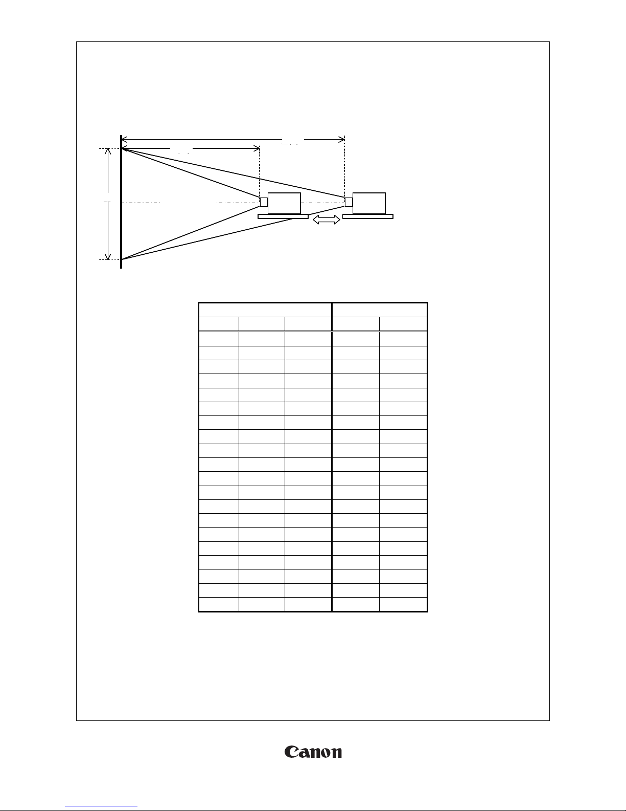
1-3 4K adaptive wide zoom lens
In addition to supporting 4K high definition, the projection lens of this product is designed with a throw ratio
between 1.0 and 1.3, which is wider than typical standard projection lenses. This feature can meet customer
needs in the simulation market and the like.
Further, the lens is designed so that the f-number is F2.6 over the entire zoom region. As such, the variation
in brightness due to zoom control is suppressed to minimum.
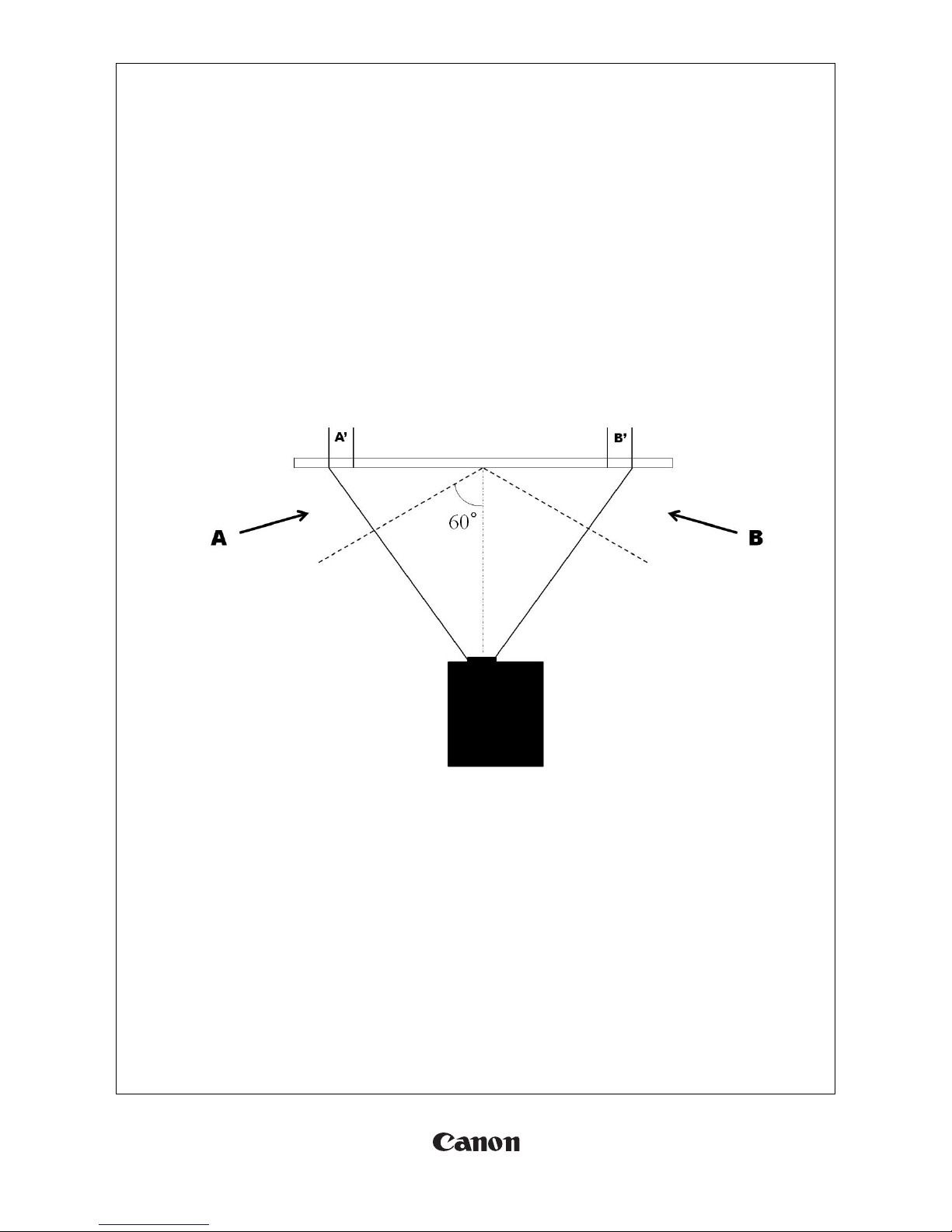
1-4 High-definition edge blending technologies
The product contains technologies that make edge blending projection, a way of connecting multiple images,
more beautiful.
1) Low distortion projection lens with no more than 0.12% TV distortion.
2) Sub pixel correction that electrically corrects color displacement in unit of 0.1 pixels in a specific area of the
screen.
3) Equipped with a framed mask to shield the extra light around the LCOS panel
1-5 Curved surface projection technologies
The product includes technologies for projecting images beautifully onto a dome-shaped screen and the like.
1) Supports curved surface screens with a periphery focus adjustment function that corrects the curvature of
the image field and an optical correction function that is separate from the general focus drive.
2) Ensures field of depth with a large f-number (F2.6) projection lens and provides beautiful projection onto a
curved surface as the f-number can be increased with the variable aperture arranged inside the illumination
optical system.
3) Has an exterior where a portrait mirror can be mounted
1-6 Optimal movie performance for simulation applications
In order to accommodate simulation applications, this product includes technologies for producing 4K movies
in real time with low level of motion blurring.
1) Low-delay playback that suppresses the delay from input to display to about 1.0 frame (at 60 Hz) (*3)
2) Employs a new system for movie visibility improvement (MB reduction) to display smoother movies than
before.
1-7 HDMI 2.0 / HDCP 2.2
The built-in HDMI 2.0 port enables 4K video playback at 60 Hz from a Blu-ray player via an HDMI cable.
Further, protection of high quality 4K contents has become stronger with the compliance of HDCP 2.2, the
latest encryption technology for copyright protection.
*1: The function that is displayed as “Advanced registration” on the menu screen
*2: Adjustable for 9x6 points.
*3: Keystone and other scaling functions are off. The image input is DVI 1x4 or HDMI 1x2.

(2/22)
2. Specifications
2-1 Basic specifications
Model
4K501ST
1)
Product type
Projector
Type
Imaging device, number
Reflective LCD panel (LCOS) ×3
2)
Number of pixels
4096×2400
LCOS
Size, Aspect ratio
0.76 inch, 128:75 (about 17:10)
panel
Driving system
Active Matrix
3)
Lens configuration
12 groups 16 elements
Projection
F number, Focal length
F2.6, f=17.2 – 22.3 mm
lens
Zoom magnification
1.3 times
Projection distance
0.9 – 17.7 m
Distance for 100 “ image
2.2 – 2.9 m
Throw ratio (*1)
1.0:1 -1.3:1
Operation
Zoom: powered, Focus: powered, Lens shift: Powered
Marginal focus: powered
4)
Type
Super High Pressure Lamp for projectors
Light source
Power (*2)
400/300 W
5)
Optical system
Dichroic mirror and PBS color separation-combination system
Images
Brightness (*2)
5000/3750 lm
Marginal lumination ratio
88%
Contrast ratio
3000:1
Image size (4096 x 2400)
40 – 600 inches
Lens shift
V: ± 60%, H: ±10%
Electronic zoom (for length)
Not provided
Keystone correction
V ±20°, H ±20°
6)
DVI-D x4
Digital PC input
Terminals
HDMI x2
Digital PC/Digital video input
Mini jack x2
Audio input x1, Audio output x1
Mini jack x1
Wired remote control connection
Dsub9
RS-232C connection
USB Type A
USB connection
RJ-45
Network connection (1000BASE-T / 100BASE-TX / 10BASE-T)
6)
DVI (single)
640x480, 800x600, 1280x720, 1024x768, 1366x768, 1440x900, 1280x1024,
1920x1080, 2048x1080, 2560x1080, 1920x1200, 2048x1200, 2560x1440,
3840x2160(*3), 4096x2160(*3)(*4)
Image
DVI 1x2
2560x1080, 2560x1440, 2560x1600, 3840x2160(*3), 4096x2160(*3)
signals
DVI 2x2
3840x2160, 4096x2160,4096x2304(*5), 3200x2400(*5), 3840x2400(*5),
4096x2400(*5)
DVI 1x4
3840x2160, 4096x2160, 4096x2304(*5), 3840x2400(*5), 4096x2400(*5)
HDMI (single)
640x480, 720x480, 720x576, 800x600, 1280x720, 1024x768, 1366x768, 1440x900,
1280x1024, 1920x1080, 2048x1080, 2560x1080, 1920x1200, 2048x1200,
2560x1440, 2560x1600, 3840x2160, 4096x2160
HDMI 1x2
1280x480, 1440x480, 1440x576, 2560x720, 3840x1080, 2560x1600, 3840x2160,
4096x2160, 3200x2400(*5), 3840x2400(*4)(*5)
8)
Adjustable feet
Four locations on the bottom, Extension length: 12 mm
Mechanics
Built-in speaker
5 W, Monaural
Dimensions
W: 470 mm, H: 175 mm, D: 533.5 mm
Weight
18 kg
Noise level (*2)
39/34 dB
9)
Power supply
AC100 - 240 V :50/60 Hz
Others
Power consumption (*2)
600/475 W
Stand-by powerconsumption(*6)
0.8/0.4 W
Operation environment
0°C–40°C, 20%RH –85%RH
Storage environment
-20°C–60°C
*1: Calculated value for 70” image
*2: Lamp mode is Full power/Power saver. Brightness in Power saver mode is only a calculated value, and is not guaranteed as specification
*3: Only low frequencies (24 to 30 Hz) are supported.
*4: EDID is not supported.
*5: Supported when “Panel drive mode” is set to “4096x2400”
*6: Network “ON” (Low-power) / “OFF”

(3/22)
2-2 Image size and projection distance
This product is suited to project pictures in maximum size of 600 inches.
Projection distance to the corresponding picture size is as follows.
Note that zoom and focus operations on this product is powered.
Image of height H is projected in
the range from the shortest
distance L (W) to the longest
distance L (T).
(W) means the wide end and (T)
means the tele end.
This product allows the lens shift
ratio to be varied.
The left figure shows an example
of 1:1 and image is divided with
the optical axis at the center.
4K501ST
Image size (4096x2400)
Projection distance [m]
[inches]
Width [m]
Height [m]
L(W)
L(T)
40
0.9
0.5
0.9
1.1
60
1.3
0.8
1.3
1.7
80
1.8
1.0
1.8
2.3
100
2.2
1.3
2.2
2.9
120
2.6
1.5
2.7
3.5
140
3.1
1.8
3.1
4.1
160
3.5
2.1
3.6
4.7
180
3.9
2.3
4.0
5.3
200
4.4
2.6
4.5
5.8
220
4.8
2.8
4.9
6.4
240
5.3
3.1
5.4
7.0
260
5.7
3.3
5.9
7.6
280
6.1
3.6
6.3
8.2
300
6.6
3.9
6.8
8.8
350
7.7
4.5
7.9
10.3
400
8.8
5.1
9.0
11.8
450
9.9
5.8
10.2
13.2
500
11.0
6.4
11.3
14.7
550
12.1
7.1
12.4
16.2
600
13.2
7.7
13.6
17.7
The distances listed on the table have been rounded off and are therefore approximate values.
HProjector Projector
L(W)
L(T)
Optical axis
HProjector Projector
L(W)
L(T)
Optical axis

(4/22)
2-3 Lens shift function and image position
This product has a lens shift function that can move the image position vertically and horizontally.
The followings are the lens shift specifications of the 4K501ST.
Model
4K501ST
Amount of Lens shift
(V) -60% ~ 60%
(H) -10% ~ 10%
Lens shift ratio
(V) -1:11~11:-1
(H) 4:6~6:4
The following figure shows the area in which the image can be moved and the guaranteed optical performance
range of this product.
The center of the crosshair is the optical axis of the lens.
The octagonal area excluding the four corners (light gray) is the guaranteed optical performance range. Note
that the sizes of the four corners that are outside the guaranteed range are the same.
※Moving the image outside the guaranteed optical performance range may cause shade to appear in the corner area of the
image. (e.g., 60% vertical, 10% horizontal →the upper right corner of the image becomes dark)
We recommend that you do not use the product in this manner but rather adjust the installation position so that the image
is within the guaranteed range.
15%
10%
60%
-60%
10%
-10%

!
;.?!QAF+-*%E5)!=))*!
!
!
!! !
!
!
!
!
!
!
!
!
Four adjustable feet
are provided on the
bottom of the product.
The length of these feet
can be adjusted to
minimize the horizontal tilt of the image
projected on the screen.!
!
!
R0*%*&0'!
!
!
!
Rotate the adjustable legs to adjust their
lengths.
The maximum extension length of each leg
is 12 mm.!
!
!
!
!
!
The front-to-back angle of this product can
be adjusted in the range of ±1.5
relative to
the surface that the product is placed on.!
!
* The figure is for explanation only and different from the actual product shape.!
!
!
!
ST*)'-&0'!
QAF+-*%E5)!=))*!

(6/22)
2-5 Notes on installation
Because this product adopts a wide angle lens, the following phenomenon may arise. These are not failures,
and there is no problem with this product.
・Image coloring
When the image is viewed at an angle of 60 degrees or more from the front, a portion of the
image appears colored.
If viewed from the left, the left side of the image appears colored in magenta. If viewed from
the right, the right side of the image appears in the same way.
Likewise, if viewed from a vertical angle, the top or bottom side appears colored in green.
This is particularly evident in whitish images.
This phenomenon occurs as a result of polarization properties but may not be noticeable
depending on the screen type.
The following figure shows an example when the image is viewed from the sides.
If viewed from direct A, area A’ appears colored in magenta.
If viewed from direct B, area B’ appears colored in magenta.

(7/22)
3. Image signals
3-1 Number of terminals used for image input
This product is equipped with a system that transmits image signals through several transmission cables to
display high resolution image signals that could not be transmitted previously with a single transmission
cable (DVI, HDMI).
The different combinations of image input terminals that the product uses are shown below.
①Single terminal input (DVI1, DVI2, DVI3, DVI4, HDMI1, HDMI2)
The conventional method of transmitting image signals using a single transmission cable.
The screen of the output equipment is played back as is.
②Two terminal input (DVI1+DVI3, HDMI1+HDMI2)
A method of transmitting image signals using two transmission cables.
For example, when transmitting a 3840x2160 image, each cable carries a 1920x2160 signal.
Image signals are divided into two signals, transmitted, composed, and played back.
For DVI, signalA is received through DVI1 and signal B through DVI3.
For HDMI, signalA is received through HDMI1 and signal B through HDMI2.
③Four terminal input, quadrant (DVI 2x2)
One of the methods of transmitting image signals using four transmission cables.
For example, when transmitting a 3840x2160 image, each cable carries a 1920x1080 signal.
Image signals are divided into quadrants, transmitted, composed, and played back.
Signal A is received through DVI1, signal B through DVI2, signal C through DVI3, and signal D through
DVI4.

(8/22)
④Four terminal input, side by side (DVI 1x4)
One of the methods of transmitting image signals using four transmission cables.
For example, when transmitting a 3840x2160 image, each cable carries a 960x2160 signal.
Image signals are divided horizontally into four parts, transmitted, composed, and played back.
Signal A is received through DVI1, signal B through DVI2, signal C through DVI3, and signal D through
DVI4.
●
Notes for receiving signals through multiple terminals
In order to reproduce images correctly when an image signal is divided and received through multiple
terminals, the following items must at least be the same for each of the divided image signals.
・Period
・Resolution, frequency
・Color format
These are the typically same because it is assumed that images from a single output device will be divided
and output. However, this may not be true depending on the specifications of the output device.
3-2 About Multi input mode select
On this product, EDID (a list of resolutions that can be received) is selected using “Multi input mode select”.
(The EDID is selected separately for DVI and HDMI.) (*1)
If set to “Normal the EDID will be a list containing a portion of the image signals that use a single terminal
and a portion of the image signals that use several terminals.
With this setting, image signals with different number of terminals can be selected on the image output
equipment side and output.
However, because not all image signals can be accommodated, if a setting is not in the list, the following
menu is used to select a setting with specific number of terminals.
Install settings →Professional settings →Multi input mode select
Here, the DVI or HDMI setting is changed from Standard to the number of terminals to be used (Single, 1x2,
2x2, or 1x4).
*1: EDID are different between panel drive mode settings

(9/22)
3-3 Supported image signal type
Image signals that the product can display are listed below.
The description of blanking information is provided later.
Interlace signals are denoted with (I).
For DVI input, a signal whose dot clock is less than 165 MHz is a single link signal, and that whose dot
clock is 165 MHz or higher is a dual link signal.
●DVI (single)
Resolution
Frequency
Setting (*1)
Blanking information
Horizontal
[kHz]
Vertical
[Hz]
Dot clock
[MHz]
Normal
Single
Horizontal
FP, SW, BP
Vertical
FP, SW, BP
640x480
31.469
59.940
25.175
○
○
16, 96, 48
10, 2, 33
800x600
37.879
60.317
40.000
○
○
40, 128, 88
1, 4, 23
1280x720
45.000
60.000
74.250
○
○
110, 40, 220
5, 5, 20
1024x768
48.363
60.004
65.000
○
○
24, 136, 160
3, 6, 29
1366x768
47.712
59.790
85.500
-
○
70, 143, 213
3, 3, 24
48.000
60.000
72.000
(*2)
14, 56, 64
1, 3, 28
1440x900
55.935
59.887
106.500
○
○
80, 152, 232
3, 6, 25
55.469
59.901
88.750
○
○
48, 32, 80
3, 6, 17
1280x1024
63.981
60.020
108.000
○
○
48, 112, 248
1, 3, 38
1920x1080
27.000
24.000
74.250
○
○
638, 44, 148
4, 5, 36
67.500
60.000
148.500
○
○
88, 44, 148
4, 5, 36
2048x1080
66.576
59.924
147.000
(*2)
48, 32, 80
3, 10, 18
67.500
60.000
148.500
○
○
44, 44, 64
4, 5, 36
2560x1080
66.636
59.978
181.250
(*2)
48, 32, 80
3, 10, 18
66.000
60.000
198.000
-
○
248, 44, 148
4, 5, 11
1920x1200
74.556
59.885
193.250
○
○
136, 200, 336
3, 6, 36
74.038
59.950
154.000
○
○
48, 32, 80
3, 6, 26
2048x1200
74.049
59.959
163.500
○
○
48, 32, 80
3, 10, 22
2560x1440
88.787
59.951
241.500
-
○
48, 32, 80
3, 5, 33
3840x2160
52.438
23.999
209.750
-
○
48, 32, 80
3, 5, 17
4096x2160
52.397
23.980
223.000
(*2)
48, 32, 80
3, 10, 12
●DVI 1x2
Resolution
Frequency
Setting (*1)
Blanking information
Composed
Divided
Horizontal
[kHz]
Vertical
[Hz]
Dot clock
[MHz]
Normal
1x2
Horizontal
FP, SW, BP
Vertical
FP, SW, BP
2560x1080
1280x1080
66.493
59.850
95.750
-
○
48, 32, 80
3, 10, 18
2560x1440
1280x1440
88.715
59.902
127.750
-
○
48, 32, 80
3, 10, 28
2560x1600
1280x1600
98.611
59.910
142.000
○
○
48, 32, 80
3, 10, 33
3840x2160
1920x2160
52.512
23.956
132.750
(*2)
104, 200, 304
3, 10, 19
52.404
23.983
109.000
(*2)
48, 32, 80
3, 10, 12
54.000
24.000
148.500
(*3)
○
638, 44, 148
8, 10, 72
67.500
30.000
148.500
(*2)
○
88, 44, 148
8, 10, 72
4096x2160
2048x2160
52.515
23.957
142.000
(*2)
112, 216, 328
3, 10, 19
52.423
23.992
115.750
(*2)
48, 32, 80
3, 10, 12
54.000
24.000
148.500
(*3)
○
510, 44, 148
8, 10, 72
67.500
30.000
148.500
(*2)
○
44, 44, 64
8, 10, 72
*1: Indicates multi input mode settings that allow image signal to be used
*2: Since EDID is not supported, the setting has no effect (standard recommended).
*3: Only when the “Panel drive mode” is set to “4096x2160”

(10/22)
●DVI 2x2
Resolution
Frequency
Setting (*1)
Blanking information
Composed
Divided
Horizontal
[kHz]
Vertical
[Hz]
Dot clock
[MHz]
Normal
2x2
Horizontal
FP, SW, BP
Vertical
FP, SW, BP
3840x2160
1920x1080
27.000
24.000
74.250
○
○
638, 44, 148
4, 5, 36
33.750
30.000
74.250
○
○
88, 44, 148
4, 5, 36
66.587
59.934
138.500
○
○
48, 32, 80
3, 5, 23
67.158
59.963
173.000
○
○
128, 200, 328
3, 5, 32
67.500
60.000
148.500
○
○
88, 44, 148
4, 5, 36
4096x2160
2048x1080
27.000
24.000
74.250
-
(*3)
594, 44, 64
4, 5, 36
33.750
30.000
74.250
-
(*3)
44, 44, 64
4, 5, 36
66.576
59.924
147.000
-
○
48, 32, 80
3, 10, 18
67.160
59.964
183.750
(*2)
128, 216, 344
3, 10, 27
67.500
60.000
148.500
○
○
44, 44, 64
4, 5, 36
4096x2304
(*5)
2048x1152
71.584
59.903
197.000
(*4)
(*4)
136, 216, 352
3, 5, 35
70.992
59.909
156.750
(*4)
(*4)
48, 32, 80
3, 5, 25
72.000
60.000
162.000
(*4)
(*4)
26, 80, 96
1, 3, 44
3200x2400
(*5)
1600x1200
74.006
59.924
130.250
-
(*4)
48, 32, 80
3, 4, 28
75.000
60.000
162.000
-
(*4)
64, 192, 304
1, 3, 46
74.556
59.885
193.250
○
(*4)
136, 200, 336
3, 6, 36
74.038
59.950
154.000
○
(*4)
48, 32, 80
3, 6, 26
4096x2400
(*5)
2048x1200
74.582
59.905
205.250
(*2)
136, 216, 352
3, 10, 32
74.049
59.959
163.500
○
(*4)
48, 32, 80
3, 10, 22
●DVI 1x4
Resolution
Frequency
Setting (*1)
Blanking information
Composed
Divided
Horizontal
[kHz]
Vertical
[Hz]
Dot clock
[MHz]
Normal
1x4
Horizontal
FP, SW, BP
Vertical
FP, SW, BP
3840x2160
960x2160
134.036
59.918
178.000
(*2)
80, 104, 184
3, 10, 64
133.259
59.973
149.250
-
(*3)
48, 32, 80
3, 10, 49
133.319
60.000
138.652
(*2)
8, 32, 40
48, 8, 6
135.000
60.000
148.500
○
○
44, 22, 74
8, 10, 72
4096x2160
1024x2160
134.055
59.926
188.750
(*2)
80, 112, 192
3, 10, 64
133.235
59.962
157.750
-
(*3)
48, 32, 80
3, 10, 49
133.320
60.000
147.185
(*2)
8, 32, 40
48, 8, 6
135.000
60.000
148.500
○
○
22, 22, 32
8, 10, 72
4096x2304
(*5)
1024x2304
142.103
59.959
168.250
-
(*4)
48, 32, 80
3, 10, 53
143.111
59.979
201.500
(*2)
80, 112, 192
3, 10, 69
142.199
60.000
156.988
-
(*4)
8, 32, 40
52, 8, 6
3840x2400
(*5)
960x2400
147.991
59.940
165.750
-
(*4)
48, 32, 80
3, 10, 56
149.096
59.974
198.000
(*2)
80, 104, 184
3, 10, 73
148.139
60.000
154.065
(*4)
(*4)
8, 32, 40
55, 8, 6
4096x2400
(*5)
1024x2400
148.970
59.924
209.750
(*2)
80, 112, 192
3, 10, 73
148.015
59.949
175.250
-
(*4)
48, 32, 80
3, 10, 56
148.139
60.000
163.546
(*4)
(*4)
8, 32, 40
55, 8, 6
*1: Indicates multi input mode settings that allow image signal to be used
*2: Since EDID is not supported, the setting has no effect (standard recommended).
*3: Only when the “Panel drive mode” is set to “4096x2160”
*4: Only when the “Panel drive mode” is set to “4096x2400”
*5: In the case of an image signal whose vertical resolution exceeds 2160, if the panel drive mode is set to “4096x2160”,
it will be processed as “no signal.” Therefore, set the mode to “4096x2400.”

(11/22)
●HDMI (single)
Resolution
Frequency
Setting (*1)
Blanking information
Horizontal
[kHz]
Vertical
[Hz]
Dot clock
[MHz]
Normal
Single
Horizontal
FP, SW, BP
Vertical
FP, SW, BP
640x480
31.469
59.940
25.175
○
○
16, 96, 48
10, 2, 33
720x480
31.469
59.940
27.000
○
○
16, 62, 60
9, 6, 30
720x576
31.250
50.000
27.000
○
○
12, 64, 68
5, 5, 39
800x600
37.879
60.317
40.000
○
○
40, 128, 88
1, 4, 23
1280x720
18.000
24.000
59.400
○
○
1760, 40, 220
5, 5, 20
37.500
50.000
74.250
○
○
440, 40, 220
5, 5, 20
45.000
60.000
74.250
○
○
110, 40, 220
5, 5, 20
1024x768
48.363
60.004
65.000
○
○
24, 136, 160
3, 6, 29
1366x768
47.712
59.790
85.500
-
○
70, 143, 213
3, 3, 24
48.000
60.000
72.000
(*2)
14, 56, 64
1, 3, 28
1440x900
55.935
59.887
106.500
○
○
80, 152, 232
3, 6, 25
55.469
59.901
88.750
○
○
48, 32, 80
3, 6, 17
1280x1024
63.981
60.020
108.000
○
○
48, 112, 248
1, 3, 38
1920x1080(I)
28.125
50.000
74.250
○
○
528, 44, 148
4.5, 10, 30.5
31.250
50.000
72.000
(*2)
32, 168, 184
45.5, 10, 114.5
33.750
60.000
74.250
○
○
88, 44, 148
4.5, 10, 30.5
1920x1080
27.000
24.000
74.250
○
○
638, 44, 148
4, 5, 36
56.250
50.000
148.500
○
○
528, 44, 148
4, 5, 36
67.500
60.000
148.500
○
○
88, 44, 148
4, 5, 36
2048x1080
66.576
59.924
147.000
○
○
48, 32, 80
3, 10, 18
67.500
60.000
148.500
○
○
44, 44, 64
4, 5, 36
2560x1080
26.400
24.000
99.000
○
○
998, 44, 148
4, 5, 11
56.250
50.000
185.625
○
○
548, 44, 148
4, 5, 36
66.636
59.978
181.250
(*2)
48, 32, 80
3, 10, 18
66.000
60.000
198.000
○
○
248, 44, 148
4, 5, 11
1920x1200
74.556
59.885
193.250
○
○
136, 200, 336
3, 6, 36
74.038
59.950
154.000
○
○
48, 32, 80
3, 6, 26
2048x1200
74.582
59.905
205.250
○
○
136, 216, 352
3, 10, 32
74.100
60.000
157.684
(*2)
8, 32, 40
21, 8, 6
2560x1440
88.787
59.951
241.500
-
○
48, 32, 80
3, 5, 33
98.713
59.972
268.500
○
○
48, 32, 80
3, 6, 37
3840x2160
52.593
23.993
266.750
(*2)
216, 400, 616
3, 5, 24
52.438
23.999
209.750
(*2)
48, 32, 80
3, 5, 17
54.000
24.000
297.000
○
○
1276, 88, 296
8, 10, 72
56.250
25.000
297.000
○
○
1056, 88, 296
8, 10, 72
67.500
30.000
297.000
○
○
176, 88, 296
8, 10, 72
112.500
50.000
594.000
○
○
1056, 88, 296
8, 10, 72
135.000
60.000
594.000
○
○
176, 88, 296
8, 10, 72
4096x2160
52.561
23.979
284.250
(*2)
224, 432, 656
3, 10, 19
52.397
23.980
223.000
(*2)
48, 32, 80
3, 10, 12
54.000
24.000
297.000
○
○
1020, 88, 296
8, 10, 72
56.250
25.000
297.000
○
○
968, 88, 128
8, 10, 72
67.500
30.000
297.000
○
○
88, 88, 128
8, 10, 72
112.500
50.000
594.000
○
○
968, 88, 128
8, 10, 72
135.000
60.000
594.000
○
○
88, 88, 128
8, 10, 72
*1: Indicates multi input mode settings that allow image signal to be used
*2: Since EDID is not supported, the setting has no effect (standard recommended).
*3: Only when the “Panel drive mode” is set to “4096x2160”
*4: Only when the “Panel drive mode” is set to “4096x2400”

(12/22)
●HDMI 1x2 ** Follow HDMI-1.4 standards when you input with two HDMI terminals.
Resolution
Frequency
Setting (*1)
Blanking information
Composed
Divided
Horizont
al
[kHz]
Vertical
[Hz]
Dot clock
[MHz]
Normal
1x2
Horizontal
FP, SW, BP
Vertical
FP, SW, BP
1280x480
640x480
31.469
59.940
25.175
○
○
16, 96, 48
10, 2, 33
1440x480
720x480
31.469
59.940
27.000
○
○
16, 62, 60
9, 6, 30
1440x576
720x576
31.250
50.000
27.000
○
○
12, 64, 68
5, 5, 39
2560x720
1280x720
37.500
50.000
74.250
○
○
440, 40, 220
5, 5, 20
45.000
60.000
74.250
○
○
110, 40, 220
5, 5, 20
3840x1080
(I)
1920x1080
(I)
28.125
50.000
74.250
○
○
528, 44, 148
4.5, 10,
30.5
33.750
60.000
74.250
○
○
88, 44, 148
4.5, 10,
30.5
3840x1080
1920x1080
67.500
60.000
148.500
○
○
88, 44, 148
4, 5, 36
2560x1600
1280x1600
98.611
59.910
142.000
-
○
48, 32, 80
3, 10, 33
3840x2160
1920x2160
52.512
23.956
132.750
(*2)
104, 200, 304
3, 10, 19
52.404
23.983
109.000
(*2)
48, 32, 80
3, 10, 12
54.000
24.000
148.500
(*3)
638, 44, 148
8, 10, 72
112.500
50.000
297.000
-
○
528, 44, 148
8, 10, 72
133.293
59.988
277.250
(*2)
48, 32, 80
3, 10, 49
135.000
60.000
297.000
○
○
88, 44, 148
8, 10, 72
133.320
60.000
266.640
(*2)
8, 32, 40
48, 8, 6
4096x2160
2048x2160
52.515
23.957
142.000
(*2)
112, 216, 328
3, 10, 19
52.423
23.992
115.750
(*2)
48, 32, 80
3, 10, 12
54.000
24.000
148.500
○
○
510, 44, 148
8, 10, 72
112.500
50.000
297.000
-
○
484, 44, 64
8, 10, 72
133.265
59.975
294.250
(*2)
48, 32, 80
3, 10, 49
133.320
60.000
283.704
(*2)
8, 32, 40
48, 8, 6
135.000
60.000
297.000
○
○
44, 44, 64
8, 10, 72
3200x2400(*5)
1600x2400
148.011
59.948
260.500
-
(*4)
48, 32, 80
3, 10, 56
3840x2400(*5)
1920x2400
148.140
60.000
296.280
(*2)
8, 32, 40
55, 8, 6
*1: Indicates multi input mode settings that allow image signal to be used
*2: Since EDID is not supported, the setting has no effect (standard recommended).
*3: Only when the “Panel drive mode” is set to “4096x2160”
*4: Only when the “Panel drive mode” is set to “4096x2400”
*5: In the case of an image signal whose vertical resolution exceeds 2160, if the panel drive mode is set to
“4096x2160”, it will be processed as “no signal.” Therefore, set the mode to “4096x2400.”
●
About blanking information
The following figure shows the structure of the blanking period that is inserted between image signal
frames.
FP: front porch, SW: synchronizing width, BP: back porch
Effective image
Effective image
F
SW
BP
Image signal
Synchronizing signal
Blanking period

(13/22)
3-4 HDMI deep color compatibility table
●RGB444 and YCbCr444
Resolution
(single terminal)
Frequency
8bit
support
10bit
support
12bit
support
Horizontal
[kHz]
Vertical
[Hz]
Dot clock
[MHz]
640x480
31.469
59.940
25.175
○
○
○
720x480
31.469
59.940
27.000
○
○
○
720x576
31.250
50.000
27.000
○
○
○
1280x720
18.000
24.000
59.400
○
○
○
37.500
50.000
74.250
○
○
○
45.000
60.000
74.250
○
○
○
1920x1080(I)
28.125
50.000
74.250
○
○
○
31.250
50.000
72.000
○
○
○
33.750
60.000
74.250
○
○
○
1920x1080
27.000
24.000
74.250
○
○
○
56.250
50.000
148.500
○
○
○
67.500
60.000
148.500
○
○
○
2560x1080
26.400
24.000
99.000
○
○
○
56.250
50.000
185.625
○
-
-
66.000
60.000
198.000
○
-
-
3840x2160
54.000
24.000
297.000
○
-
-
56.250
25.000
297.000
○
-
-
67.500
30.000
297.000
○
-
-
112.500
50.000
594.000
○
-
-
135.000
60.000
594.000
○
-
-
4096x2160
54.000
24.000
297.000
○
-
-
56.250
25.000
297.000
○
○
○
67.500
30.000
297.000
○
○
○
112.500
50.000
594.000
○
-
-
135.000
60.000
594.000
○
-
-
●YCbCr420
Resolution
(single terminal)
Frequency
8bit
support
10bit
support
12bit
support
Horizontal
[kHz]
Vertical
[Hz]
Dot clock
[MHz]
3840x2160
112.500
50.000
594.000
○
○
○
135.000
60.000
594.000
○
○
○
4096x2160
112.500
50.000
594.000
○
○
○
135.000
60.000
594.000
○
○
○

(14/22)
3-5 Internal functions
●
HDCP
This product is an HDCP version 2.2/1.4-compliant image device.
The digital image signals for HDCP contents that are encrypted and sent from digital devices connected
to the HDMI terminal and DVI terminal can be displayed.
HDCP is an “encryption system for digital video signals.”
It AISYS a TMDS link with DVI or HDMI terminals.
HDCP transmitter is built in the signal server and HDCPreceiver is built in the signal receiver.
This system can make the signals code, transmit, decode and display.
1. The transmitter authenticates the receiver: If the authentication fails, signals are not transmitted.
Immediately after authentication, a key (the encryption rule) is shared: The key is updated every two
seconds.
2. The transmitter encrypts the information with the key and sends the encrypted (digital) signal. If the
key update does not match, the transmissions stop.
3. The receiver receives the encrypted signal, decodes the signal with the key, and displays the signal on
the display device.
●
Frame lock function
Depending on the input signal’s frequency, commonly-used display devices may not be able to synchronize
the input signal’s frame with LCD’s frame, thereby showing a mixture of successive 2 frames.
The following illustrates how this mixture of frames (image shift) occurs. Numbers ①to ③indicates the
order in which these images appeared.
In this example, a composite image ②appeared when an object moved from right to left, which is a
combination of the frames before and after the movement.
This function synchronizes the LCD’s frame with that of input signal to prevent this kind of frame mixture,
and it is effective for input signals of about 23 to 31 Hz and about 47 to 61 Hz.
For frequencies other than these ranges, a different process takes effect in place of Frame Lock
(synchronization) to ensure that a single frame appears in the entire LCD. Therefore, composite image like
②would not appear even in those cases.
In the past, asynchronous methods were adequate for inputs from computers because they mainly
consisted of still images so no image overlapping could be seen. When moving images are played back,
however, image-overlapping takes place because of a slight difference between the image signal and the
LCOS-panel drive frequency. As more moving images are played back from computers these days, the
frame lock function is used to synchronize computer inputs to counteract this problem, resulting in
smooth image playback.
① ② ③

(15/22)
5. States of this product
4-1 States
This product is in one of six states.
State (*1)
Outline
No Power
No power is being supplied from outside.
The projector does not operate at all.
Off (Standby)
Power is being supplied from outside. However, the circuit is only partially
live and the projector itself is not active.
Depending on the Network function setting, this status can be categorized into
3 modes.
Projection (On)
A status where the projector is used normally.
Power is being supplied to the entire circuit.
The lamp is lit, and image is projected.
Lamp Off
Power is supplied to the entire circuit except panel circuit.
The lamp is unlit and the cooling fan is operating.
Some action changes the projector to the projection state. However, the lamp
on time is the same as actual activation.
Error
Power is being from outside but the projector cannot be activated.
To use the projector, action should be taken according to the contents of the
error type.
Pre-warning
High temperature
If the temperature becomes almost abnormal, the projector displays the
warning of high temperature.
This state is cleared when the temperature goes down.
Pre-warning
Lamp replacement
If the lamp replacement conditions are almost satisfied, the projector displays
the warning of the lamp replacement.
This state is cleared when the lamp counter for replacement is reset.
4-2 Type of Error
Each error state is defined as below.
Error name
Outline
Temperatu r e a b n o r m a l i ty
・The internal temperature is abnormally high.
・The outside air temperature is higher than specified.
・Malfunction of thermal sensor
Faulty lamp
・The lamp is out of life.
・The lamp drive circuit is faulty.
Faulty lamp cover
・The lamp cover is not closed.
Faulty air filter unit
・No air filter is attached.
Faulty cooling fan
・The cooling fan does not operate normally.
Faulty power supply
・The supply voltage is abnormal.
・Other abnormal is occurred.
Faulty lens shift connector
・Lens shift connector is not connected
(It is necessary to detect the lens shift position)
** Each error state may be caused by a fault other than the above.

(16/22)
5. Accessories
5-1
Main
Supplied
Accessories
Remote Control
RS-RC05
Power supply: DC 3.0V (with two AA battery)
Communication range: approx. 8 m within ±25 degrees of the
receiver
Allows for wireline connection (*1)
Power code
Connects the unit to a power source.
5-2
Optional
Parts
Ceiling Attachment
RS-CL15 (*2)
This is used for ceiling mount. (*1)
Ceiling Pipe 400-600mm
RS-CL08
The RS-CL08 is used in combination with the RS-CL15 to
suspend the projector at a distance below the ceiling.
Ceiling Pipe 600-1000mm
RS-CL09
The RS-CL09 is used in combination with the RS-CL15 to
suspend the projector at a distance below the ceiling.
Remote Control
RS-RC04
Power supply: DC 3.0V (with two AAA battery)
Communication range: approx. 8 m within ±25 degrees of the
receiver
Remote Control
RS-RC05
Same as the supplied remote.
5-3
Replacement
Parts
Lamp Assembly
with Replacement Air Filter
RS-LP10F
(RS-LP10+RS-FL03)
RS-LP10
Super High Pressure Lamp for projectors
Recommended lamp replacement time (*3)
400 W: 3000H, 300 W: 4000H
Replacement air filter
RS-FL03
This filter is installed at the air intake to prevent dust from
entering.
*1: Uses a commercially available audio cable (3.5Фstereo mini-plug) for cable connection.
*2: Do not attach a difference model’s attachment. The size and the weight of a product are different from other modes.
Consult a building professional before attempting to mount the projector to a ceiling.
*3: This time guarantees a 50% survival rate and a 50% brightness-maintenance rate.
This value does not guarantee the service life of the lamp.

(17/22)
6. Product Appearance
6-1 Outline Drawings
●Dimensions:
W: 470.0 mm, H: 175.0 mm, D: 533.5 mm (18.5 x 6.9 x 21.1 inch ) * including protrusion
W: 470.0 mm, H: 155.0 mm, D: 515.0 mm (18.5 x 6.1 x 20.3 inch ) * not including protrusion
Lens center: 122.0 mm from the left side (‘front” is the side where lens is attached.)
100.0 mm from the installed surface
●Weight: 18 kg (40 lbs)
●Screw holes for ceiling mount: 4 (M6)

(18/22)
6-2 Part Names
① Projection lens
② LED indicator
③ Te r m i n a l s a n d connecto r s
④ Side control
⑤ Power cord connector
⑥ Infrared remote receiver
⑦ Adjustable feet
⑧ Air intake vent
⑨ Anti-theft lock hole
⑩ Lamp cover
⑪ Exhaust vent
⑫ Infrared remote receiver

(19/22)
6-3 Terminals
Type
Term in a l
Signal
Image input
①
HDMI (1)
Digital PC/Digital video
HDMI (2)
Digital PC/Digital video
②
DVI-D (1)
Digital PC
DVI-D (2)
Digital PC
DVI-D (3)
Digital PC
DVI-D (4)
Digital PC
Audio input
⑥
Mini jack
Stereo audio
Audio output
⑦
Mini jack
Stereo audio
Control
③
Dsub9
RS-232C connection
④
RJ-45
1000BASE-T/100BASE-TX/10BASE-T
⑤
USB type A
USB connection
⑧
Mini jack
Wired remote control connection
●Wireline connection for the remote
The unit can be operated by a wired remote RS-RC05 (option).
When a cable is connected to the unit’s remote terminal, the unit switches to a mode in which no infrared signal
is accepted, so that the unit would not respond to other remote.
In addition, when a cable is connected to the wireline connection terminal on the remote, the remote also
switches to a mode in which no infrared signal is transmitted.
When the remote is wired, the user does not have to make the channel settings on the unit or the remote.
**Note:
If the cable connecting the unit and the remote breaks, the unit will become inoperable from any remote.

(20/22)
6-4 Indicators and Control buttons
Illuminate to indicate the projector state.
POWER ON
(Green)
Lit
Projection state
Blinking
Initializing (Off → Projection)
Off
Other than above
STAND BY
(Red)
Lit
Off state
Blinking
Shutting down (Projection →Off)
Off
Other than above
WARNING
(Red)
Lit
Error state
Blinking
Error state
Off
No error state
LAMP
(Orange)
Lit
Lamp error (*1), Lamp cover error (*2)
Blinking
When the lamp replacement period approaches
Off
Other than above
TEMP
(Red)
Lit
Tem p er a t u re e rr o r
Blinking
When a temperature error condition is imminent
Off
Other than above
By the combination of indicator states, various other states are indicated.
For details, refer to the user's manual.
*1: [Warning] lights together. *2: [Warning] blinks together.
Control the projector by button operation.
①
POWER
Turns the power supply on or off.
②
INPUT
Displays a select screen of input signal for projection.
③
LENS
Changes the display to the focus, marginal focus (when activated), zoom, or lens
shift adjustment screen each time the button is pressed.
④
KEYSTONE
Displays the adjustment screen of H-V keystone or Corner adjustment
⑤
Direction /
VOL
Adjust the volume. (Right and left only)
Move the pointer vertically or horizontally on a menu screen or other
⑥
OK
Confirms a state selected on a menu screen or other.
⑦
MENU
Displays a menu screen.
Table of contents
Other Canon Projector manuals

Canon
Canon LV-7105 User manual

Canon
Canon LV-X4 LV-7230 User manual

Canon
Canon LV-7290 User manual

Canon
Canon WX6000 Installation manual

Canon
Canon 1318C002 User manual

Canon
Canon RealIS SX6 User manual

Canon
Canon REALiS SX7 Mark II D User manual

Canon
Canon LV-7285 User manual

Canon
Canon WUX450 User manual

Canon
Canon D-50P User manual

Canon
Canon LV-7385 User manual

Canon
Canon LV-7380 User manual

Canon
Canon LV 7490 User manual

Canon
Canon REALiS SX80 Mark II D Owner's manual

Canon
Canon RE-450X User manual

Canon
Canon LV-7370 User manual

Canon
Canon Rayo S1 User manual

Canon
Canon 7365 - LV XGA LCD Projector User manual

Canon
Canon SX800 - REALiS SXGA+ LCOS Projector User manual

Canon
Canon REALiS SX80 Mark II D Manual