WA0375E_WSD10TGII_User Manual_R08
V4.6
CAPETTI ELETTRONICA s.r.l. - Strada Stratta 57
10090 CASTIGLIONE TORINESE - TORINO - ITALY
VAT 04837130014 - Phone 011.981.98.11 - Fax 011.981.98.210
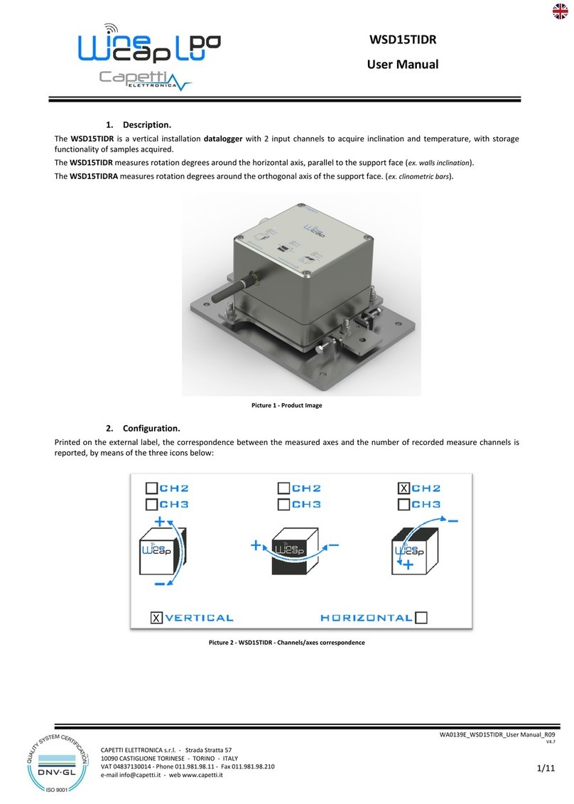
3. Clinometer feature.
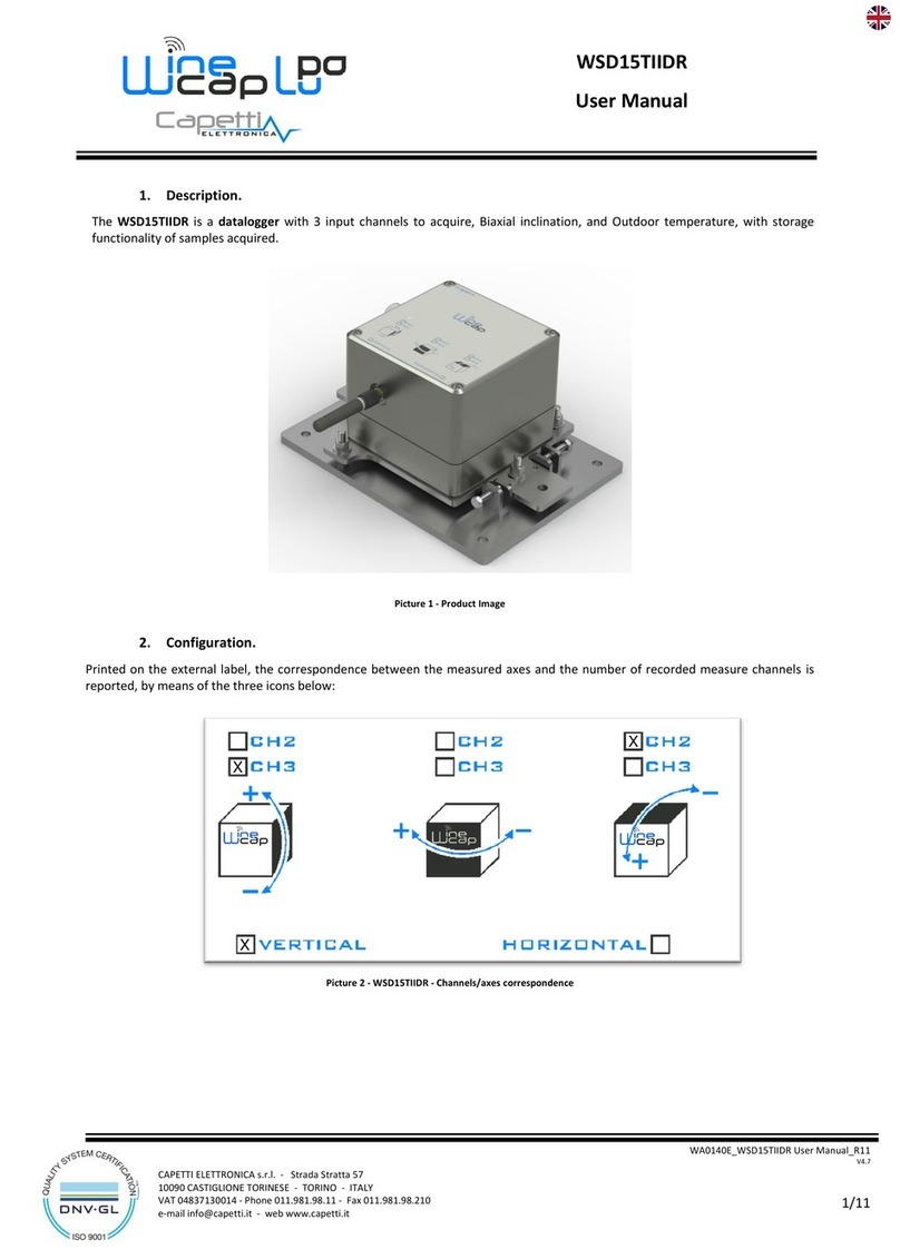
On channels 3 and 4, tilt values, related to vertical position, are measured.
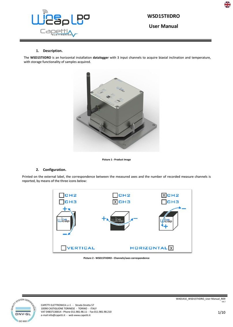
On the external label the correspondence between measured axis and channel numbers is showed as follow (Pic. 2):
The front side of the cube corresponds with the one with the label, while the black side indicates the side of the drawed rotation
refers to, versus included. As showed in figure above, CH3 measures the tilt related to the horizontal axis coplanar to surface,
positive in front sense, while CH4 measures the lateral tilt, around to normal axis of surface, positive in counterclockwise sense.
Once installed the datalogger, up to two warning thresholds per tilt channel can be set. Thresholds can be both set in the direction
and with the versus of the measure to be done (refer to “WineCapManager” software manual) with sampling interval selectable by user.
4. Device preset and use mode.
a. Wireless Mode:
No setup operation is needed. Typically the system is configured from factory so the device is already associated to the system
basestation. The device is in STANDBY mode (refer to Picture 5 - Status table - Radio signal quality) for which is necessary to start it
with the TEST command (refer to Installation procedure.).
Otherwise, in case the device is in FACTORY RESET mode (refer to Picture 5 - Status table - Radio signal quality), that means it's ready
for connecting to an existing system, in order to associate it, make reference to the “WineCap System - User Manual R29”software
manual. Is necessary to use the "WineCapManager" software on the PC connected to the basestation that will be coupled with
the device.
b. USB Logger Mode:
For this operation mode, stand-alone with data downloads through USB, the connection with the PC and the
“WineCapManager” running on it is necessary in order to modify the device 's operation mode. The sampling interval must be
set with the device in "STAND-ALONE" (refer to Stand-alone USB datalogger installation.) mode and automatically, the device 's clock
is aligned with the PC's clock, in order to assure the temporal reference of the sample.
Sampling operations start may be selected disconnecting the USB cable or giving the proper command with the magnetic key.
(refer to Stand-alone USB datalogger installation.). More details on device 's connection/disconnection through the USB cable are
available on the WineCap System - User Manual R29 manual.
c. On field transition from USB to Wireless datalogger:
This transition is practicable in field, during the sampling period, using the wireless network association command. When the
association is done, the datalogger becomes a wireless datalogger and, besides sending new measures to the basestation,
starts a download process towards the same basestation of the measures acquired during the stand alone period (refer to
Picture 6 - Stand-alone datalogger status).
Picture 2 - Device positioning - Tilt measure axis
