manuals.online logo
Brands
  1. Home
  2. •
  3. Brands
  4. •
  5. Carel
  6. •
  7. Controllers
  8. •
  9. Carel MCHRTF Series User manual

Carel MCHRTF Series User manual

General characteristics
The MCHRTF series electronic devices are single-phase voltage controllers that use the principle of phase control to adjust
the eective voltage output to the load, based on the phase of the PWM control signal (see Fig. 3, which refers to the case
of a resistive load).
One typical application is the speed control of single-phase condenser fan motors, based on the pressure or the temperatu-
re measured on the heat exchanger.
The MCHRTF controllers are protected against short circuit with a fuse located on the outside of the board, thus allowing
easy inspection and replacement, where necessary (refer to Table 3 for the correct replacement of the fuse). Always check
with the manufacturers that the motors used are suitable for operation with phase control devices.
Assembling the controller in the panel
The controller is mounted using plastic spacers (supplied), to be inserted in the four holes on the board. To optimise the
dissipation of the heat produced, the device should be installed in environments where the temperature does not exceed 50
°C and there is sucient air circulation.
The 8/12 A models should be installed in such a way that the ns on the heat sink are arranged vertically (see Fig. 2).
The installer must guarantee the safety of the device.
Electrical connections
The controller should be connected as illustrated in Fig. 2. The speed controller must be connected to the control device as
follows:
Install a safety disconnecting switch upstream on the supply line (230 Vac) so as to be able to isolate the device for•
inspection.
Connect the power supply (230 Vac) to terminals L and N. Connect the fan motor to the terminals marked LOAD.•
Before powering up the controller, check the power connections and in 8/12 A devices, make sure the earth connection•
is correct.
For the power connections and the earth wire, use cables with the cross-section shown in the table of technical•
specications (Tab 1).
The PWM control signal is applyed to terminals +/- on the device.•
For the PWM control signal, use a shielded cable with a maximum length of 5 m, and keep the cable separate from•
other power cables.
The power supply to the controller and the fan speed control board must be in phase. If, for example, the power supply is•
three-phase, make sure that the primary of the power transformer on the control board is connected to the same phase
as terminals L and N on the speed control board or boards; consequently, do not use 400 Vac / 24 Vac transformers to
supply the controller if phase and neutral are used to directly power the speed control boards.
Commissioning
After having checked the connections, power up the board and apply the PWM signal from the controller: when displa-
cement changes compared to the mains, the eective voltage at the controller output will vary from 0 to 230 V. In the
case of resistive loads and a mains frequency of 50 Hz, the input/output characteristic is shown in Fig. 4: the x-coordinate
represents the displacement, while the y-coordinate indicates the eective voltage supplied at the output to the load.
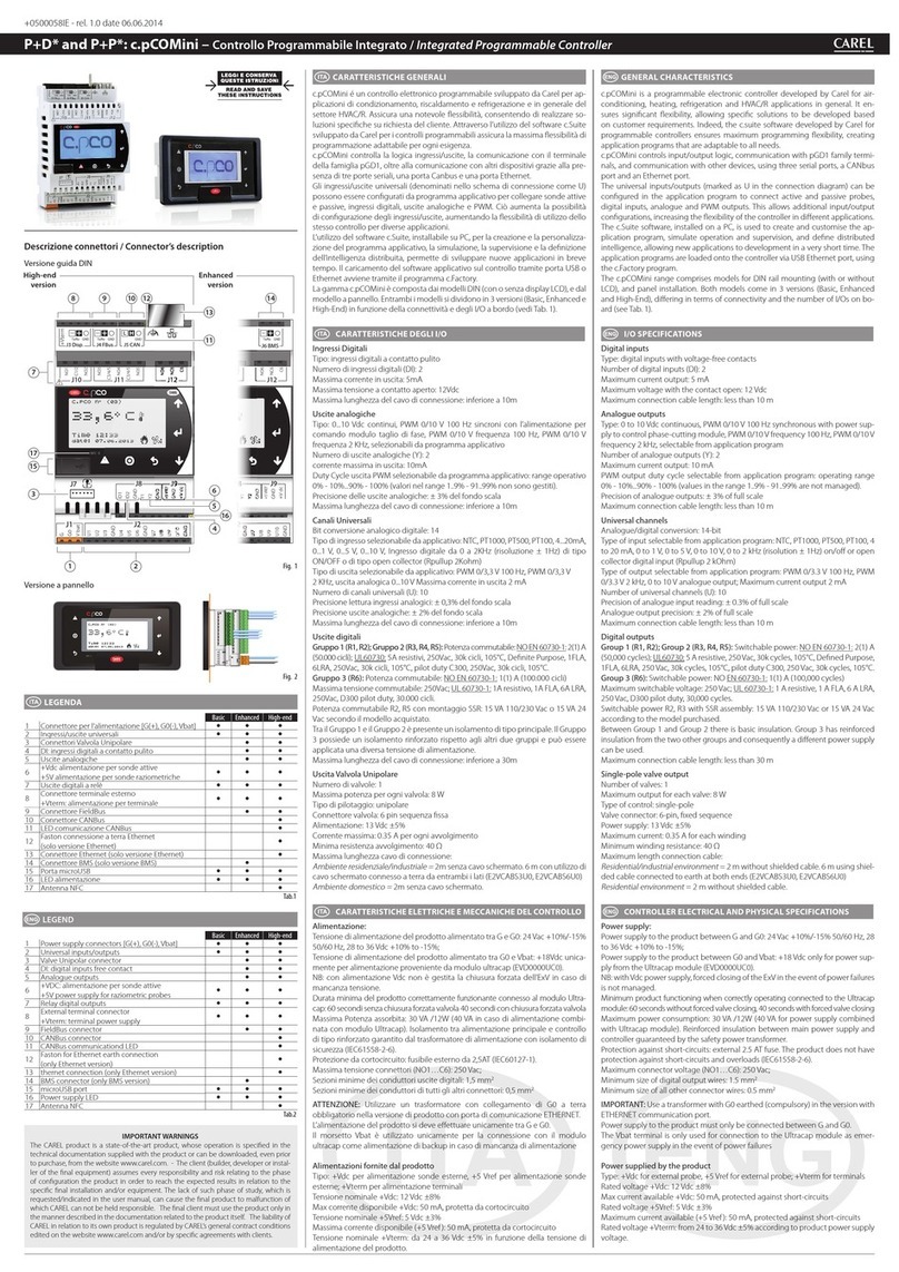
Regolatori di velocità monofase serie MCHRTF/MCHRTF series single phase fan speed controller
+050002855 - rel. 1.2 del 29.04.2008
Caratteristiche generali
Le apparecchiature elettroniche della serie MCHRTF sono regolatori di tensione monofase che utilizzano il principio del
taglio di fase per regolare la tensione ecace in uscita al carico, in base alla fase del segnale PWM di comando (vedi
Fig. 3, che si riferisce al caso di carico resistivo).
Una tipica applicazione è quella della regolazione di velocità dei motori dei ventilatori monofase di condensazione, in
base alla pressione o alla temperatura misurata sullo scambiatore stesso.
I regolatori MCHRTF sono protetti da cortocircuito per mezzo di un fusibile posto sulla parte esterna della scheda,
in modo da poter essere facilmente ispezionato e, se necessario, facilmente sostituito (riferirsi allaTab. 3 per la
corretta sostituzione). Si raccomanda di vericare con i costruttori che i motori utilizzati siano idonei all’utilizzo con la
regolazione a taglio di fase.
Montaggio del regolatore nel quadro
Il regolatore è montato mediante distanziali plastici (forniti in dotazione) da inserire nei relativi quattro fori della
scheda. È consigliabile, per ottimizzare lo smaltimento di calore prodotto, installare l’apparecchiatura in ambienti in cui
la temperatura non superi i 50 °C e vi sia una suciente circolazione d’aria.
Per i modelli a 8/12 A è opportuno orientare il regolatore in modo che le alette del dissipatore siano verticali (vedi Fig.
2). E’a cura dell’installatore la messa in sicurezza dell’apparecchiatura.
Collegamenti elettrici
Il regolatore va collegato come illustrato in Fig. 2. Il regolatore di velocità deve essere abbinato
al controllo facendo attenzione a quanto segue:
Predisporre un sezionatore di sicurezza a monte dell’alimentazione (230Vac) in prossimità dell’apparecchio, in modo•
da poterla interrompere per eventuali ispezioni.
Collegare l’alimentazione (230Vac) ai morsetti L e N. Collegare il motore del ventilatore ai morsetti LOAD.•
Prima di alimentare il regolatore, controllare le connessioni di potenza e nei modelli a 8 A e 12 A, vericare l’ecien-•
za della connessione verso terra.
Per le connessioni di potenza e il cavo di terra, utilizzare cavi aventi la sezione riportata nella tabella delle caratteri-•
stiche tecniche (Tab. 1).
Il segnale di comando a modulazione di impulsi (PWM) viene applicato sui morsetti +/- del dispositivo.•
Per il segnale di comando PWM, utilizzare un cavo di lunghezza massima 5 m, e tenere separato il cavo da altri cavi•
di potenza.
Le alimentazioni del controllo e della scheda parzializzazione ventilatori devono essere in fase; ad esempio nel caso•
di alimentazione trifase del sistema, assicurarsi che il primario del trasformatore di alimentazione della scheda del
controllo sia allacciato alla stessa fase collegata ai morsetti L e N della o delle schede di regolazione di velocità; non
utilizzare quindi trasformatori 400Vac / 24Vac per l’alimentazione del controllo qualora si utilizzino fase e neutro per
alimentare direttamente le schede di regolazione velocità.
Messa in servizio
Dopo aver vericato i collegamenti, alimentare la scheda e applicare il segnale PWM proveniente dal controllo: al
variare del suo sfasamento rispetto alla tensione di rete, la tensione ecace in uscita dal regolatore varia da 0 a 230
V. Nel caso di carico resistivo e frequenza di rete 50 Hz, la caratteristica ingresso/uscita è riportata in Fig. 4: in ascissa è
indicato lo sfasamento, mentre in ordinata è indicata la tensione ecace fornita in uscita al carico.
Dimensioni (mm)/Dimensions (mm)
Modello
Model
A (lato componenti)
A (component side)
B
B
C
C
D
D
E
E
MCHRTF04C0 43 100 40 50 107
MCHRTF08C0/E0 75 100 58 82 107
MCHRTF12C0/E0 75 100 58 82 107
Nota: su richiesta disponibile la versione morsetti a vite codice MCHRTF*D0
Note: version with screw terminals code MCHRTF*D0 available upon request
4 A
A
D
A
D
BE
BE
C
C
8 e 12 A
Fig. 1
CAREL S.p.A.
Via dell’Industria, 11 - 35020 Brugine - Padova (Italy)
Tel. (+39) 0499716611 – Fax (+39) 0499716600 http://www.carel.com – e-mail: carel@carel.com
+050002855 - rel. 1.2 del 29.04.2008
Caratteristiche tecniche
Alimentazione monofase 230Vac +10% / -15%
Frequenza 50/60 Hz
Caratteristiche dello stadio di ingresso
+
-
Ingresso Opto isolato
Segnale di
controllo PWM
18 0 Ω
Impedenza di ingresso 180 Ω
Temperatura di lavoro -10T50 °C
Temperatura di immagazzinamento -20T70 °C
Tipo di azione – disconnessione 1Y
Grado di protezione IP00 (scheda a giorno)
Grado di inquinamento del dispositivo di comando II
Categoria di protezione alle sovratensioni III
Periodo di sollecitazioni elettriche delle parti isolanti Lungo
Sezione min dei cavi di collegamento
Regolatori 4/8 A
Regolatori 12 A
1,5 mm2
2,5 mm2
Nota: se il regolatore viene usato alla massima temperatura di lavoro e a pieno carico, fare uso di cavi con massima tempera-
tura operativa almeno 105 °C
Tab. 1
Nota: per il modello 12 A sull’uscita al carico utilizzare cavo schermato con schermo collegato alla terra dal lato scheda.
Caratteristiche del segnale di ingresso
Segnale di comando PWM per taglio di fase (0...5V)
Corrente di comando minima 10 mA
Durata minima dell’impulso 2 msec
Tab. 2
Nota: La durata dell’impulso va programmata in funzione del tipo di motori da controllare.
Caratteristiche di isolamento
•3750Vactraingressodelsegnaledipilotaggioepartiintensionedeldispositivo
•1250Vactraterradiprotezioneepartiintensionedeldispositivoperimodelli8Ae12A
Il dispositivo da 4 A è adatto per l’installazione in apparecchiature di classe I e II.
I dispositivi da 8 A e 12 A sono adatti per l’installazione in apparecchiature di classe I.
Modello Corrente
nominale [A]
Corrente di
spunto [A]
Corrente Max
ammessa [A]
Fusibili
MCHRTF04C0 4 4 x Inom. Inom +10% Ceramico 5x20 5 A rit.
MCHRTF08C0/E0 8 3 x Inom. Inom +10% Ceramico 6.3x32 8 A rit.
MCHRTF12C0/E0 12 3 x Inom. Inom +10% Ceramico 6.3x32 12 A rit.
Tab. 3
I modelli MCHRTF*C0 sono CE conformi alle direttive europee 72/23 CEE, 89/336 CEE e aggiornamenti successivi in
base alle norme: EN 55014-1; EN 55014-2; EN 61000-6-1; EN 61000-6-2; EN 61000-6-3; EN 61000-6-4; EN 60730-1;
EN 61010-1.I modelli MCHRTF*E0 sono conformi alle direttive CEI EN 61000-6-2;CEI EN 61000-6-4;CEI EN 60730-1;CEI
EN 61010-1.
Attenzione: presenza di tensione di rete sulla scheda.
Smaltimento del prodotto
L’apparecchiatura (o il prodotto) deve essere oggetto di raccolta separata in conformità alle vigenti normative locali in materia di
smaltimento
AVVERTENZE IMPORTANTI
Il prodotto CAREL è un prodotto avanzato, il cui funzionamento è specicato nella documentazione tecnica fornita col prodotto o scaricabile, anche
anteriormente all’acquisto, dal sito internet www.Carel.com. Il cliente (costruttore, progettista o installatore dell’equipaggiamento nale) si assume
ogni responsabilità e rischio in relazione alla fase di congurazione del prodotto per il raggiungimento dei risultati previsti in relazione all’installazione
e/o equipaggiamento nale specico. La mancanza di tale fase di studio, la quale è richiesta/indicata nel manuale d’uso, può generare malfunziona-
menti nei prodotti nali di cui CAREL non potrà essere ritenuta responsabile. Il cliente nale deve usare il prodotto solo nelle modalità descritte nella
documentazione relativa al prodotto stesso. La responsabilità di CAREL in relazione al proprio prodotto è regolata dalle condizioni generali di contratto
CAREL editate nel sito www.Carel.com e/o da specici accordi con i clienti.
Technical specications
Single-phase power supply 230 Vac +10% / -15%
Frequency 50/60 Hz
Characteristics of the input stage
+
-
Opto insulated input
PWM
control signal
18 0 Ω
Input impedance 180 Ω
Operating temperature -10T50 °C
Storage temperature -20T70 °C
Type of action – disconnection 1Y
Index of protection IP00 (open board)
Pollution of the control device II
Category of protection against voltage surges III
Period of electrical stress across the insulating parts Long
Min cross-section of the connection cables
4/8 A device
12 A device
1.5 mm2
2.5 mm2
Note: if using the controller at maximum operating temperature and full load, use cables with maximum operating temperature
at least 105 °C
Tab. 1
Note: for the 12 A device, use a shielded cable with the shield connected to earth on the board side.
Input signal characteristics
Control signal PWM for phase control (0 to 5 V)
Minimum current control 10 mA
Minimum duration of the impulse 2 msec
Tab. 2
Note: The duration of the impulse should be set depending on the type of motors being controlled.
Insulation characteristics
•3750Vacbetweenthecontrolsignalinputandthelivepartsofthedevice
•1250Vacbetweentheearthandthelivepartsofthedevicefor8Aand12Amodels
The 4 A device is suitable for installation in class I and II appliances.
The 8 A and 12 A devices are suitable for installation in class I appliances.
Model Rated current [A] Peak current [A] Max current [A] Fuses
MCHRTF04C0 4 4 x r. current r. current +10% Ceramic 5x20 5 A T.
MCHRTF08C0/E0 8 3 x r. current r. current +10% Ceramic 6.3x32 8 A T.
MCHRTF12C0/E0 12 3 x r. current r. current +10% Ceramic 6.3x32 12 A T.
Tab. 3
MCHRTF*C0 models have the CE mark and comply with the EEC directives 72/23, 89/336 and subsequent updates, based
on the standards: EN 55014-1; EN 55014-2; EN 61000-6-1; EN 61000-6-2; EN 61000-6-3; EN 61000-6-4; EN 60730-1;
EN 61010-1.MCHRTF*E0 models are CEI EN 61000-6-2; CEI EN 61000-6-4; CEI EN 60730-1; CEI EN 61010-1 certied.
Warning: mains voltage on the board.
Disposal of the product
The appliance (or the product) must be disposed of separately in accordance with the local waste disposal legislation in force
IMPORTANT WARNINGS
The CAREL product is a state-of-the-art device, whose operation is specied in the technical documentation supplied with the product or can be downlo-
aded, even prior to purchase, from www.carel.com. The customer (manufacturer, developer or installer of the nal equipment) accepts all liability and risk
relating to the conguration of the product in order to reach the expected results in relation to the specic nal installation and/or equipment. The failure
to complete such phase, which is required/indicated in the user manual, may cause the nal product to malfunction; CAREL accepts no liability in such
cases. The customer must use the product only in the manner described in the product documentation. The liability of CAREL in relation to its products is
specied in the CAREL general contract conditions, available at www.carel.com and/or by specic agreements with customers.
Fig. 3
Collegamenti elettrici/Electrical connections
Fig. 2
Fig. 4
+ -
4 A
LOADNLLOADNL
M
230 V a c
Segnale di controllo PWM
PWM control signal
Segnale di controllo PWM
PWM control signal
M
230 V a c
+V
+ -
LINEA
LINE
LINEA
LINE
8 e 12 A
0
020406080100120140160180
50
100
150
200
250
Caratteristica Ingresso/Uscita (Frequenza 50 Hz)
Input/output characteristics (frequency 50 Hz)
Angolo di accensione [gradi]/Starting angle [degrees]
VAC OUT [V]
Tensione che va ad essere disponibile al carico
Voltage made available to the load
Vac
Ingresso PWM
PWM input
impulso
impulse

This manual suits for next models

3

Other Carel Controllers manuals

Carel e-drofan User manual

Carel

Carel e-drofan User manual

Carel KITCONT101SP User manual

Carel

Carel KITCONT101SP User manual

Carel pCO2 Series User manual

Carel

Carel pCO2 Series User manual

Carel UltraCella Instruction Manual

Carel

Carel UltraCella Instruction Manual

Carel ir33 platform User manual

Carel

Carel ir33 platform User manual

Carel uPC Manual

Carel

Carel uPC Manual

Carel pRack pR300T User manual

Carel

Carel pRack pR300T User manual

Carel mPCII User manual

Carel

Carel mPCII User manual

Carel pRack PR100 User manual

Carel

Carel pRack PR100 User manual

Carel UltraCella WB000S F0 Series Instruction Manual

Carel

Carel UltraCella WB000S F0 Series Instruction Manual

Carel pCO Series User manual

Carel

Carel pCO Series User manual

Carel PJEZ Series User manual

Carel

Carel PJEZ Series User manual

Carel FCR3 User manual

Carel

Carel FCR3 User manual

Carel ADP 30 pAD Series User manual

Carel

Carel ADP 30 pAD Series User manual

Carel EVD4 User manual

Carel

Carel EVD4 User manual

Carel AT-th Tune User manual

Carel

Carel AT-th Tune User manual

Carel pCO3 series Manual

Carel

Carel pCO3 series Manual

Carel mastercella Manual

Carel

Carel mastercella Manual

Carel powerSplit User manual

Carel

Carel powerSplit User manual

Carel boss Series User manual

Carel

Carel boss Series User manual

Carel mboss Manual

Carel

Carel mboss Manual

Carel mboss Manual

Carel

Carel mboss Manual

Carel AT-th Tune Series User manual

Carel

Carel AT-th Tune Series User manual

Carel P+E c.pCOe User manual

Carel

Carel P+E c.pCOe User manual

Popular Controllers manuals by other brands

Love 32 B Series quick start guide

Love

Love 32 B Series quick start guide

FIBARO FGRGBWM-441 operating manual

FIBARO

FIBARO FGRGBWM-441 operating manual

PROAIM Kite-22 Ultimate Package Setup and Operational Manual

PROAIM

PROAIM Kite-22 Ultimate Package Setup and Operational Manual

Shinko PCD-33A instruction manual

Shinko

Shinko PCD-33A instruction manual

ScreenTronic ST3134 Operation and installation manual

ScreenTronic

ScreenTronic ST3134 Operation and installation manual

EuroLite 52202222 user manual

EuroLite

EuroLite 52202222 user manual

Elko iNELS RFGB-20 manual

Elko

Elko iNELS RFGB-20 manual

Crompton 3000 Series Installation and maintenance  instruction

Crompton

Crompton 3000 Series Installation and maintenance instruction

AudioCodes Mediant 2600 Quick setup guide

AudioCodes

AudioCodes Mediant 2600 Quick setup guide

Festo CMMS-AS Series Description

Festo

Festo CMMS-AS Series Description

Bosch DSA E Series installation manual

Bosch

Bosch DSA E Series installation manual

TopXGun T1-A user manual

TopXGun

TopXGun T1-A user manual

JDS Technologies HomeRunner RBI user manual

JDS Technologies

JDS Technologies HomeRunner RBI user manual

YASKAWA Motoman DX200 instructions

YASKAWA

YASKAWA Motoman DX200 instructions

Ava 110 Series quick start guide

Ava

Ava 110 Series quick start guide

elobau eloProg manual

elobau

elobau eloProg manual

Elife UNIDRIVE M series Reference manual

Elife

Elife UNIDRIVE M series Reference manual

Vacon NX series user manual

Vacon

Vacon NX series user manual

manuals.online logo
manuals.online logoBrands
  • About & Mission
  • Contact us
  • Privacy Policy
  • Terms and Conditions

Copyright 2025 Manuals.Online. All Rights Reserved.