manuals.online logo
Brands
  1. Home
  2. •
  3. Brands
  4. •
  5. CARTER-HOFFMANN
  6. •
  7. Commercial Food Equipment
  8. •
  9. CARTER-HOFFMANN EVOR230 Owner's manual

CARTER-HOFFMANN EVOR230 Owner's manual

EVO FOOD HOLDING STATIONS
For TACO BELL
Models EVOR230 & EVOL230
OWNERS / OPERATORS MANUAL
Part Number: 18400-3262 Printed in The United States of America Rev4: KBA070821
TABLE OF CONTENTS
PAGE
SAFETY PRECAUTIONS 2
FEATURES & SPECIFICATIONS 3
UNPACKING, INSPECTION & FREIGHT DAMAGE 4
INSTALLATION & STARTUP 5
CONTROL PANEL LAYOUT 6
OPERATION 6
CONTROLLER PROGRAMMING INSTRUCTIONS 7
DAILY CLEANING PROCEDURES 8
TIPS FOR CLEANING STAINLESS STEEL 9
WIRING DIAGRAM & REPLACEMENT PARTS LIST 10
TROUBLESHOOTING GUIDE 11-12
WARRANTY STATEMENT 13
EVOR230
Note: Wire rack product
holders not included
MANUFACTURED BY:
CARTER-HOFFMANN
1551 McCormick Avenue
Mundelein, IL 60060 U.S.A.
Phone: 847-362-5500
Fax: 847-367-8981
Toll Free: 800-323-9793
Email: [email protected]
READ THIS MANUAL
COMPLETELY BEFORE
OPERATING THIS
APPLIANCE
*The technical content of this manual, including any wiring diagrams, schematics, parts breakdown illustrations
and/or adjustment procedures, is intended for use by qualified technical personnel and is subject to
change without notice.
This appliance is intended to be used for commercial applications, for example, in kitchens of
restaurants, canteens, hospitals and in commercial enterprises such as bakeries, butcheries,
etc., but not for continuous mass production of food
2
NOTE: The technical content of this manual, including any wiring diagrams, schematics, parts breakdown
illustrations and/or adjustment procedures, is intended for use by qualified technical personnel and is
subject to change without notice.
SAFETY PRECAUTIONS
This appliance is not intended for use by persons (including children) with reduced physical,
sensory or mental capabilities, or lack of experience and knowledge, unless they have been
given supervision or instruction concerning use of the appliance by a person responsible for
their safety. Children should be supervised to ensure that they do not play with the appliance.
WARNING! Scalding Hazard!
To avoid scalding, do not use loaded containers
with liquids or cooking goods which become
fluids by heating in higher levels than those
which can be easily observed.
DANGER! Electrical Shock Hazard!
This symbol draws attention to potential electrical
hazards (dangerous voltage). If you do not follow
the safety instructions, you may risk injury or
death
CAUTION!
This symbol highlights instructions,
which should be followed to avoid any
risk of damage, malfunctioning and/or
breakdown of the device.
CAUTION! Hot Surface!
This symbol is a warning that the device surface
is hot when in use. Ignoring this warning shall
result in burns!
NOTE!
This symbol highlights tips and infor-
mation, which have to be followed for
an efficient and trouble-free operation of
the device.
WARNING!
This symbol highlights hazards, which
could lead to injury. Please follow the
instructions very carefully and proceed
with particular attention in these cases
IMPORTANT SAFETY INSTRUCTIONS
When using electrical appliances basic safety precautions should be adhered to, including the following:
1) Be familiar with the appliance use, limitations and associated restrictions. Operating instructions must
be read and understood by all persons using or installing this appliance.
2) This appliance must be grounded. Connect only to properly grounded outlet.
3) Use this appliance only for its intended use as described in this manual.
a. This equipment is specifically designed to hold pre-cooked food at temperature.
b.
c. This equipment is not designed for industrial or laboratory use.
4) Cleanliness of this appliance and accessories is essential to good sanitation.
5) DO NOT submerge this appliance in water. This appliance is not jet stream approved. DO NOT direct
water jet or steam jet at this appliance, or at any control panel or wiring. DO NOT splash or pour
water on, in or over any controls, control panel or wiring. DO NOT use corrosive chemicals or vapors
in this appliance.
6) DO NOT store this appliance outdoors. DO NOT use this product near water – for example,
near a kitchen sink, in a wet basement, or near a swimming pool, and the like.
7) DO NOT operate this appliance if it has a damaged cord or plug, if it is not working properly, or if it has
been damaged or dropped. Do not immerse cord or plug in water, keep cord away from heated
surfaces, and do not let cord hang over edge of table or counter.
8) Only qualified service personnel should service this appliance.
9) DO NOT cover or block any openings on the appliance.
3
FEATURES & SPECIFICATIONS
Features & Benefits
 EVOR models have the small heating cabinet on the right side. EVOL models have the small heating cabinet on the left side. Splitline models have
separate small and large side cabinets.
 Precision-engineered heat ducts with blower fan for even heat distribution throughout cabinet.
 Each side individually heated with separate, removable heating units. Digitally controlled and monitored temperature, with digital temperature read-
out; pre-set factory temperatures of 208°F (98°C) for small warming box and 158°F (70°C)for large warming box. On/Off toggle switch on each
heater.
 Designed for over-counter use with angled interior floor.
 Rod-type wire rack holders (NOT INCLUDED) and rear and bottom duct assemblies are removable for cleaning.
 Polycarbonate shields over top of opening with flip up feature on large warming box and sliding doors on small warming box enhance heating opera-
tion.
Model Overall
Dimensions *
Electrical Information
(each heater)
Description Shipping
Weight
EVOL230 32.38”H x 19.83”D x 62.25W 220-230V, 2020-2200W, 9.2-9.6A, 50/60Hz, 1Ph Small box on left 282 lbs
EVOR230 32.38”H x 19.83”D x 62.25W 220-230V, 2020-2200W, 9.2-9.6A, 50/60Hz, 1Ph Small box on right 282 lbs
*Height includes heating unit(s).
EVOR230
Resettable high limit (see page 12)
Specifications subject to change through product improvement and innovation.
4
UNPACKING AND INSPECTION
1. Remove the cabinet from shipping carton, ensuring that all packing
materials and protective plastic has been removed from the unit.
2. Inspect all components for completeness and condition.
3. If any freight damage is present, a freight claim must be filed imme-
diately with the shipping company.
4. Freight damage is not covered under warranty.
5. Check to insure all components are included: cabinet, instruction
packet, mounting brackets and additional accessories, where appli-
cable.
6. Read operation instructions completely.
7. Appliance should be thoroughly cleaned before use. See CLEAN-
ING INSTRUCTIONS in this manual (page 8).
This appliance
should be
thoroughly
cleaned prior to use.
See the CLEANING
INSTRUCTIONS in
this manual.
NOTE: DO NOT discard
the carton or other
packing materials until
you have inspected the
appliance for hidden
damage and checked it
for proper operation.
Refer to FREIGHT
DAMAGE CLAIM
PROCEDURE on
bottom of this page.
FREIGHT DAMAGE CLAIM PROCEDURE
NOTE: For your protection, please note that equipment in this shipment was carefully inspected
and packaged by skilled personnel before leaving the factory. Upon acceptance of this shipment,
the transportation company assumes full responsibility for its safe delivery.
IF SHIPMENT ARRIVES DAMAGED:
1. VISIBLE LOSS OR DAMAGE: Be certain that any visible loss or damage is noted on the freight
bill or express receipt, and that the note of loss or damage is signed by the delivery person.
2. FILE CLAIM FOR DAMAGE IMMEDIATELY: Regardless of the extent of damage. Contact
your dealer immediately.
3. CONCEALED DAMAGE: If damage is unnoticed until the merchandise is unpacked, notify the
transportation company or carrier immediately, and then file a “CONCEALED DAMAGE” claim
with them. This should be done within fifteen (15) days from the date the delivery was made to
you. Be sure to retain the container for inspection.
Carter-Hoffmann cannot assume liability for damage or loss incurred in transit, freight damage is
not covered under warranty. We will, however, at your request, supply you with the necessary
documents to support your claim.
Model Number
Electrical Specifications
IPX4
Serial Number —
Manufacture Date
To prevent an electrical shock hazard be-
tween the appliance and other appliances or
metal parts in close vicinity, an equalization-
bonding stud is provided. An equalization
bonding lead must be connected to this stud
and the other appliances/metal parts to
provide sufficient protection against
potential difference. The terminal is
marked with the following symbol:
5
LOCATION
Read equipment manual completely before installing and op-
erating the cabinet.
Unit must be installed by qualified service personnel on-
ly. Unit must be installed in such a fashion to bear the weight
of the cabinet when fully loaded; minimum 350 pounds.
The power connection for each heater is a grounded plug.
Electrical information for each heater is provided on the heat-
er serial tag on the front of each heater. Verify that the proper
electrical service required for this cabinet is available prior to
installation. Plug the power cords into grounded outlets with a
electrical service according to the electrical information pro-
vided on page 3.
INSTALLATION and START-UP
GROUNDING INSTRUCTIONS
This appliance is equipped with cords having a grounding wire with
a grounding plug which must be plugged into an outlet that is
properly installed and grounded. In the event of an electrical short
circuit, grounding reduces the risk of electric shock by providing an
escape wire for the electric current.
WARNING—Improper use of the grounding can result in a risk
of electric shock. Consult a qualified electrician or service agent if
the grounding instructions are not completely understood, or if doubt
exists as to whether the appliance is properly grounded.
If necessary, contact a licensed electri-
cian to install an appropriate 15 amp
electrical circuit with correct NEMA re-
ceptacle for each heater.
DO NOT use an extension cord.
Installation procedures must
be performed by a qualified technician
with full knowledge of all applicable
electrical codes and with proper load-
bearing hardware. Failure could result
in personal injury and property damage.
Damage to unit due to being connected
to the wrong voltage or phase is NOT
covered by warranty.
START-UP
1. Prior to use, thoroughly clean the interior of the unit, ac-
cording to the instructions in this manual (see page 8).
2. Plug the power cord of the cabinet into grounded outlets
with a electrical service according to the electrical infor-
mation provided on page 3. Set POWER switches to the
“ON” position.
3. Do not load product into the cabinet. Allow the heat to
remove any residual oils which may adhere to inside met-
al surfaces. A slight emission of vapor is common during
the first few hours of operation.
The ground prong of the power cord is
part of a system designed to protect you
from electric shock in the event of inter-
nal damage.
DO NOT cut off the large round ground
prong or twist a blade to fit an existing
receptacle.
CAUTION:
Electrical Shock Hazard
Unit is not waterproof, to avoid electrical
shock, keep unit and counter from being
submerged in water. Do not operate if
unit has been in contact with water.
IMPORTANT:
Each power cord is 6' long
IMPORTANT:
Not under warranty
WARNING:
Risk of personal injury
WARNING:
Risk of personal injury
Heater serial tag locations
Cabinet serial tag (Note
serial number if calling
for service)
CONTROL PANEL LAYOUT
On/Off Toggle
Switches
Controllers
aux
6
CAUTION:
HOT SURFACE
Inner surfaces of the unit
will be very hot during and
after operation. Avoid
touching the cabinet when
loading or removing
product.
1. Turn the power switches ON and let cabinet preheat for 30
minutes. When the cabinet is turned on, the air heater will oper-
ate until the cabinet reaches the air temperature setpoint. Each
display will read the actual temperature.
The temp icon will be illuminated when the cabinet temperature
is below the air temperature setpoint.
2. To view the temperature setpoint, press and release the SET
key.
3. After preheat, load cabinet with food product. Food is held in
various pan sizes as indicated by the spacing of the wire racks
inside the cabinet.
4. When cabinet is not in use, turn power off.
5. Cabinet must be cleaned daily. See cleaning instructions on
page 8.
OPERATION
AUX Key
(inoperable)
Set Key
Press and release
to display temper-
ature set point
Up Arrow Key
Press to increase temperature set point
(1°increments)
Down Arrow Key
Press to decrease temperature set point
(1°increments)
Digital Display
Readout
EVOR230
7
CONTROLLER PROGRAMMING INSTRUCTIONS
Each controller has been factory pre-set for an air temperature set point and a low temperature alarm set point.
In most cases, these set points will not need to be changed. However, if changes are necessary, the controller is
programmable.
*Note: If Air Temperature is programmed to another setting, the Low Temperature Alarm Setting will automatical-
ly be reset 25°F (13°C) degrees below the Air Temperature setting.
To Lock or Unlock the Controller: Press and hold both Arrow Keys at the same time for at least three sec-
onds. “oF” will display when the controller is locked; “oN” will display when the controller is unlocked.
To View the Temperature Set Point: Press and release the SET button
To Change the Temperature Set Point: Turn power ON. Press and hold the SET button for 3 seconds. The
current set point will display and “°C” will flash. Push the up or down arrow buttons to raise or lower the tempera-
ture set point in 1° increments. Push SET to store the new setting; the new temperate setting will flash 3 times
and then the display will revert back to the actual temperature. (If set button is not pushed within 13 seconds, the
new setting will be automatically set and the display will revert back to the actual temperature).
Cabinets are factory programmed to display degrees in C. To change from °C to °F, contact factory.
Factory Preset Set Points Large Side Heater Small Side Heater
Air Temperature 158°F (70°C) 208°F (98°C)
Low Temperature Alarm* 25°F (13°C) below set point 25°F (13°C) below set point
Air Temperature Operating Range 145° to 185°F (63° to 85°C) 165° to 220°F (74° to 104°C)
aux
AUX Key
(inoperable)
Set Key
Press and release
to display temper-
ature set point
Up Arrow Key
Press to increase temperature set point
(1°increments)
Down Arrow Key
Press to decrease temperature set point
(1°increments)
8
DAILY CLEANING PROCEDURES
CAUTION:
ELECTRIC SHOCK
HAZARD
Disconnect appliance from
electric power before cleaning.
CAUTION:
HOT SURFACE
Exposed surfaces can
be hot to the touch
and may cause burns. Allow
appliance to cool before clean-
ing.
IMPORTANT:
DO NOT spill or pour
water into controls,
control panel or wiring. Water
damage is not covered by the
warranty.
WARNING:
Beware of sharp edges
with sheet metal during
cleaning process.
1. After all food products have been removed from the cabinet,
turn the power switches to “OFF” and allow the cabinet to cool.
If cabinet is supplied with a plug, disconnect from power prior to
cleaning.
2. Remove the pan rack assemblies and clean according to manu-
facturer’s directions.
3. Remove the white bar from the lower edge of the larger cabinet
by lifting up and off the shoulder bolts. Wash with mild detergent
and rinse with clean damp cloth.
4. Remove the doors from the large cabinet by flipping up and
lifting off. To remove the doors from the smaller cabinet, first
remove the front door by lifting the door up and out of the track.
Then remove metal door divider track that is located between
the doors. Lastly, lift the rear door up and out of the track. Doors
should be washed with a clean damp cloth and chlorine-free
detergent. Rinse thoroughly with clean damp cloth and allow to
dry. Do not use scratch pads, abrasive cleaners, waxes, car
polish, or substances containing strong aromatic solvents or
alcohol. Do not use scratch pads or steel wool on the plastic
doors. Do not use stainless steel cleaner.
5. Remove bottom heat duct and then remove the rear heat duct
in each cabinet. Using a clean damp cloth with appropriate
cleaner (see page 9), clean the inside of the unit and the re-
moved parts. Wipe any residue with clean damp cloth. Reinstall
all parts when they are dry and clean.
6. Inspect and clean the areas where there are vents or filters,
making sure no water gets into the internal controls or electrical
areas of the cabinet.
7. Controller should be washed with a clean damp cloth and chlo-
rine-free detergent. Rinse thoroughly with clean damp cloth
and allow to dry. Do not use scratch pads, abrasive cleaners,
waxes, car polish, or substances containing strong aromatic
solvents or alcohol. Do not use stainless steel cleaner.
Rear heat ducts
Bottom heat ducts
White bar
Door divider track
Doors (flip up and
lift off)
Doors (lift up
from bottom and
lift out of track)
CAUTION:
Do not use steel wool
pads to clean cabinet.
Ferrous deposits will cause
rusting.
WARNING:
In order to achieve all
pole disconnect, un-
plug power cord from
receptacle/power source.
9
TIPS FOR CLEANING STAINLESS STEEL
CAUTION:
Cleansers, detergents, degreasers, sanitizers, or bleaching agents that contain chlorides or phosphates will
cause permanent damage to stainless steel products. The damage appears as pits, eruptions, voids, small
holes, severe discoloration or dulling of the metal finish.
Water with high chloride content can also damage stainless steel. If unsure of your water quality, we recom-
mend you have it tested. THIS DAMAGE IS PERMANENT, COSTLY TO REPAIR, AND IS NOT COV-
ERED BY THE WARRANTY.
RECOMMENDED TIPS FOR CLEANING STAINLESS STEEL
Purpose Frequency Cleaning Agent Method of Application
Routine Daily Soap, ammonia Sponge with cloth, rinse with clear water
cleaning detergent and water and wipe dry.
Smears/ As Stainless steel cleaner Rub with soft cloth as directed on package.
Fingerprints needed or similar products Rub in direction of grain of stainless steel.
Do not use on vinyl trim.
Stubborn Daily Any chloride-free Apply with damp sponge or cloth. Rub in
spots and as or direction of grain of stainless steel. Rinse
stains needed phosphate-free thoroughly, especially if cleaner contains
cleaner chlorine bleach, do not use on vinyl trim.
Hard water Daily Vinegar Swab with cloth.
spots as needed Rinse with water and wipe dry.
CAUTION:
DO NOT CLEAN THIS APPLIANCE
WITH A WATER JET OR STEAM
CLEANER
10
WIRING DIAGRAM
PART NUMBER DESCRIPTION
18600-0042 Hi Limit 120°F Snap Disc
18600-0054 Hi Limit 350°F Manual
18602-0171 Switch Boot
18602-0170 DPDT Toggle Switch
18612-0149 Heat Element 240V/2400W
18614-0275 Fan Grill
18614-0323 Muffin Fan, 230V
18614-0360 Motor, 115/230V
18616-9998 Cord Grip
18614-0321 Blower Wheel
PART NUMBER DESCRIPTION
18600-0117 Fan Safety Hi Limit 160°F w/Reset Snap Disc
18616-0041 Dixell 230V/16A 208°F Set-point Controller
18616-0042 Dixell 230V/16A 158°F Set-point Controller
18616-0040 20” Probe for EVO Heater
29038-3480 Sliding doors for small warming cavity (one
front and one back door)
16095-4196 Three-door flip up assembly (left)
16090-4197 Three-door flip up assembly (right)
REPLACEMENT PARTS LIST
Electrical Characteristics: 230 volts, 2200 watts, 9.6 Amps, 50/60Hz, 1 Ph
TROUBLESHOOTING GUIDE
Symptom Possible Cause Remedy
No power; Dixell temper-
ature controller display is
not lit
Switch is not in ON posi-
tion
Turn the switch ON
Unit is not plugged in Plug in the power cord
Circuit breaker tripped Reset the circuit breaker. If it trips again, disconnect the EVO heater
and reset once more. When it trips, call an electrician to replace the
breaker or replace the feeder.
Otherwise, investigate for a short in the heater. Test:
1. Heating element
230V - 24Ω
Replace if the difference is significant.
2. Bower motor—replace if necessary.
Advice: When testing the motor, please pay attention to: body temper-
ature (may be very hot!), rotor side wobbling, jammed rotor, partial or
complete winding shortage.
Power cord or plug is de-
fective
Replace or repair
Main switch is defective Replace it
Dixell temperature con-
troller display is not lit,
but cooling fan is running
Defective thermostat Dixell Check wires for crimping or looseness—correct if necessary
Check wire connection on thermostat terminals #5 and #6—correct
connection or replace the thermostat
Dixell temperature con-
troller display is not lit
Cooling fan is not running 1. Check the fan’s cable connection-correct if necessary
2. Cooling fan is defective—replace if necessary
Dixell Temperature con-
troller display is lit, but
the food chamber is not
heated
Heating element is cold 1. Check wires for crimping or loose connection—correct if neces-
sary
2. Check wire connections on Dixell temperature controller terminals
#8 and #9—correct loose connection
3. Check Dixell temperature controller—replace if necessary
4. Check Hi Limit 350°F—correct connection or replace Hi Limit if
necessary
5. Check heating element (see above) - replace the element if de-
fective
6. Check Hi Limit 160°F. If the Hi Limit reset button has popped up,
figure out reason, repair and reset.
Heating element is hot.
CAUTION: Heating ele-
ment may reach tempera-
ture as hot as 650°F.
1. Blower fan is loose—tighten set screw or replace
2. Check blower motor:
A. Motor is very hot: overheat protection activated; figure out why
motor has overheated, correct it, cool down motor. Replace if the
motor is faulty.
B. Motor is cold: correct connections or replace motor or
capacitor if necessary.
EVO Heater: 230VAC. Reference connections on wiring diagram (previous page)
WARNING: All operations must be performed to requirements of NFPA-70E (Standard for
Electrical Safety in the Workplace) by a qualified electrician. CALL FOR SERVICE.
11
TROUBLESHOOTING GUIDE - Continued
Symptom Possible Cause Remedy
Dixell temperature con-
troller display is lit up
and food chamber is
overheated
Heating element is hot.
CAUTION: Heating ele-
ment may reach tempera-
ture as hot as 650°F
1. Hi limit 350°F is always closed: measure temperature on it sur-
face; replace Hi Limit if it is hotter than 325°F. NOTE: When the
cover is open, the wire compartment, including the Hi Limit 350°F
is naturally cooled.
2. Dixell temperature controller is defective; replace controller
Cooling fan does not
operate
Cooling fan does not oper-
ate
1. Check Hi Limit 120°F—replace if necessary
2. Check cooling fan—replace if necessary. NOTE: The fan is con-
trolled by Hi Limit of 120°F and starts when the temperature in
the wire box is higher than 120°F. This can take up to 6 minutes.
Also, the fan might run after turning the switch OFF, until the tem-
perature falls under 120°F.
No heat Heater blower not running,
heating element not ener-
gized. WARNING: heater
blower may have failed
1. Remove cover, press Hi Limit reset button on “FAN SAFETY” limit
(Part Number: 18600-0117)
2. Check operation of heater blower; replace if necessary. NOTE:
this Hi Limit prevents an “over temp” situation INSIDE the control
unit. Ensures proper air flow throughout heater and cooling fan
operation.
Display Reads Indicates
P1 Air probe failure
HA Maximum temperature alarm
LA Low temperature alarm
EA External alarm
Temperature Controller Alarms—CONTACT SERVICE IF YOU SEE ANY OF
THESE ALARM CODES ON THE DISPLAY
For technical assistance with troubleshooting,
call Carter-Hoffmann at (800)421-3744
or (847)362-5500.
12
NOTE: Prior to calling for service
locate the serial tag on the cabinet.
You will need the serial number of
the cabinet for proper identification.
Cabinet serial tag
The cabinet is equipped with a temperature activated heat limit switch that will inter-
rupt the power to the heater tubes if the temperature inside the control box exceeds
160°F (71°C). The HIGH LIMIT/RESET can be manually reset by pushing the but-
ton located on the side of the control box as shown.
1. DISCONNECT UNIT FROM POWER SOURCE
2. Check to see if the air intake fan is free of dust, grease or other obstructions. If
there are, clean fan.
3. Reset the heat limit switch.
4. Plug unit back into proper power source and turn on.
5. If unit does not operate properly call technical service for assistance.
HEAT LIMIT SWITCH RESET
13
Carter-Hoffmann Warranty:
Carter-Hoffmann (“CARTER-HOFFMANN”) warrants to the initial purchaser of its standard Carter
Line Products that CARTER-HOFFMANN will, at its option, repair or replace, during the warranty
period set forth below, any part of such products made necessary due to a defect in material or work-
manship which is present when the product leaves its factory and which manifests itself during the war-
ranty period under normal use and service.
This warranty applies only to original equipment owned and possessed by the initial purchaser and the
warranty period begins on the date of installation for three years on parts and labor.
Repair or replacements under this warranty will be performed, unless otherwise authorized in writing
by CARTER-HOFFMANN, at its factory. All parts or components to be repaired or replaced under this
warranty are to be shipped prepaid to CARTER-HOFFMANN, with reimbursement credit for such part
or component to be given if found by CARTER-HOFFMANN to be defective.
CARTER-HOFFMANN neither makes nor assumes and does not authorize any other person to make or
assume any obligation or liability in connection with its products other than that covered in this war-
ranty. This warranty applies only within the continental United States and Canada. In Alaska and Ha-
waii, this warranty applies only to and is limited to the supply of replacement parts.
Warranty Exclusions and Limitations:
Any implied warranty of merchantability or fitness for a particular purpose is hereby specifically dis-
claimed by CARTER-HOFFMANN. There are no warranties, expressed or implied, which extend be-
yond the description on the face hereof. This warranty does not cover and CARTER-HOFFMANN shall
not under any circumstances be liable for any incidental, consequential or other damages (such as in-
jury to persons or property, loss of time, inconvenience, loss of business or profits, or other matters not
specifically covered) arising in connection with the use of, inability to use, or failure of these products.
Specifications subject to change through product improvement and innovation.
WARRANTY
Carter-Hoffmann
1551 McCormick Ave.
Mundelein, Illinois, 60060 USA
Phone: 847-362-5500 Toll free: 800-421-3744 Fax: 847-367-8981
Sales and Marketing E-mail: sales@carter-hoffmann.com
Service E-mail: [email protected]
Company Website: www.carter-hoffmann.com

This manual suits for next models

1

Other CARTER-HOFFMANN Commercial Food Equipment manuals

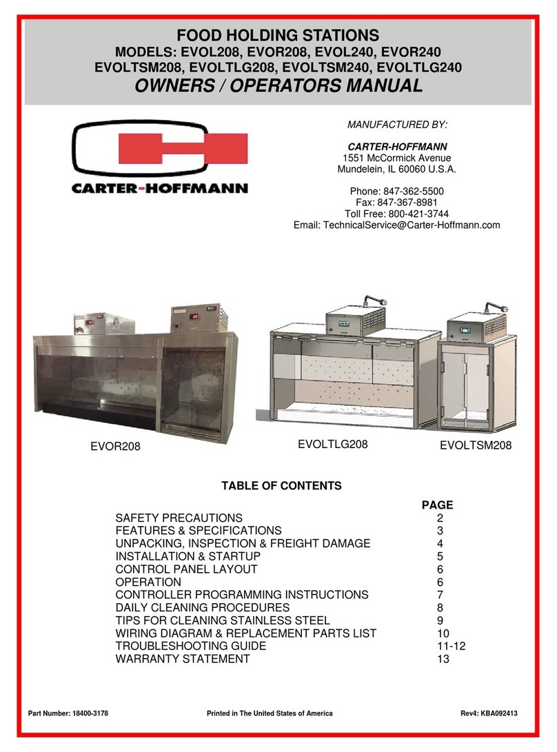
CARTER-HOFFMANN WELLS KFC PACK LINE User manual

CARTER-HOFFMANN

CARTER-HOFFMANN WELLS KFC PACK LINE User manual

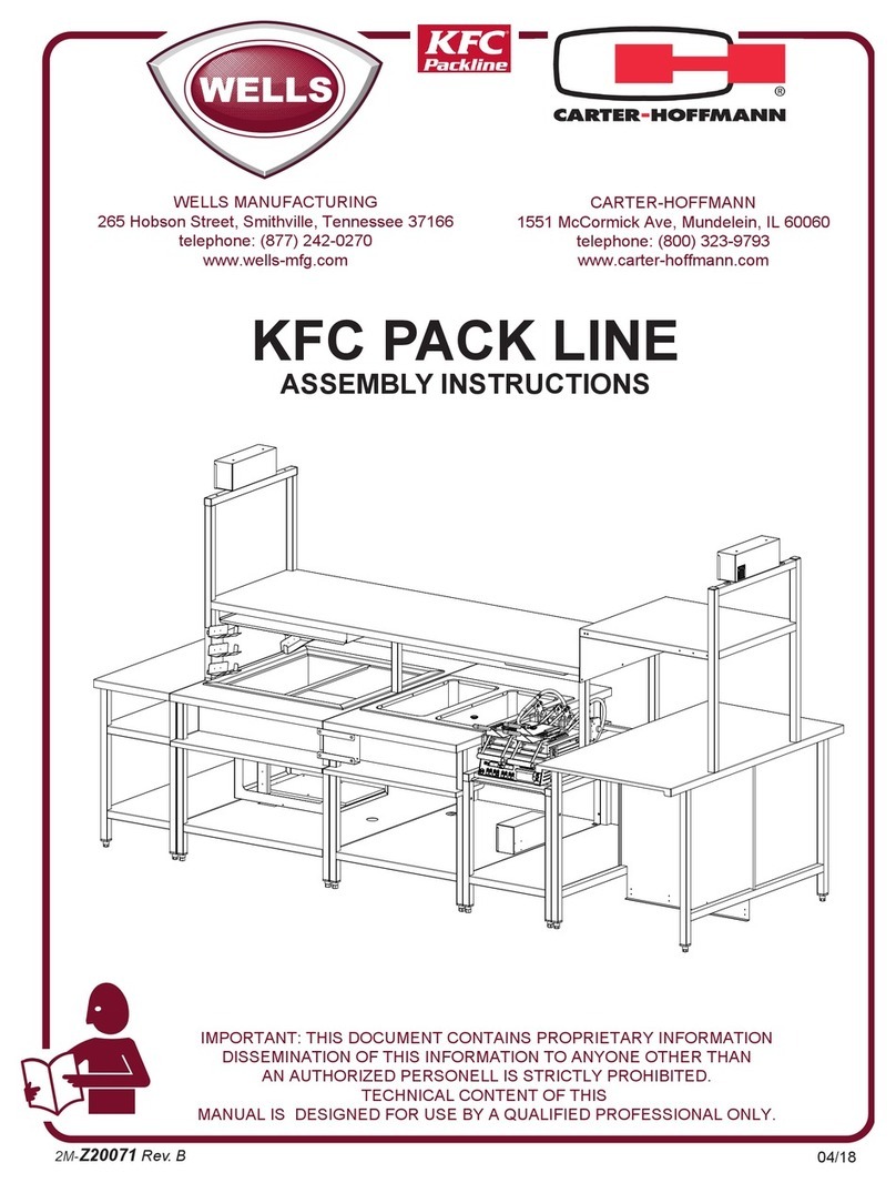
CARTER-HOFFMANN PUCA-22 Owner's manual

CARTER-HOFFMANN

CARTER-HOFFMANN PUCA-22 Owner's manual

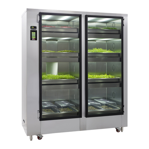
CARTER-HOFFMANN GARDENCHEF GC52 User manual
CARTER-HOFFMANN

CARTER-HOFFMANN GARDENCHEF GC52 User manual

CARTER-HOFFMANN EVOR208 User manual

CARTER-HOFFMANN

CARTER-HOFFMANN EVOR208 User manual

CARTER-HOFFMANN GardenChef GC42 User manual

CARTER-HOFFMANN

CARTER-HOFFMANN GardenChef GC42 User manual

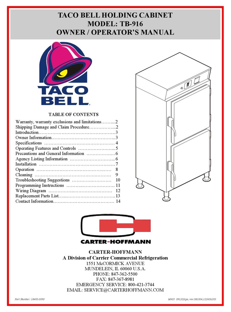
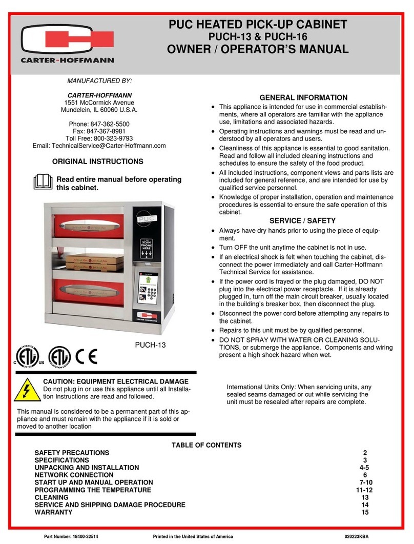
CARTER-HOFFMANN TACO BELL TB-916 Owner's manual

CARTER-HOFFMANN

CARTER-HOFFMANN TACO BELL TB-916 Owner's manual

CARTER-HOFFMANN MC243S-2T User manual

CARTER-HOFFMANN

CARTER-HOFFMANN MC243S-2T User manual

CARTER-HOFFMANN PUCH-13 User manual

CARTER-HOFFMANN

CARTER-HOFFMANN PUCH-13 User manual
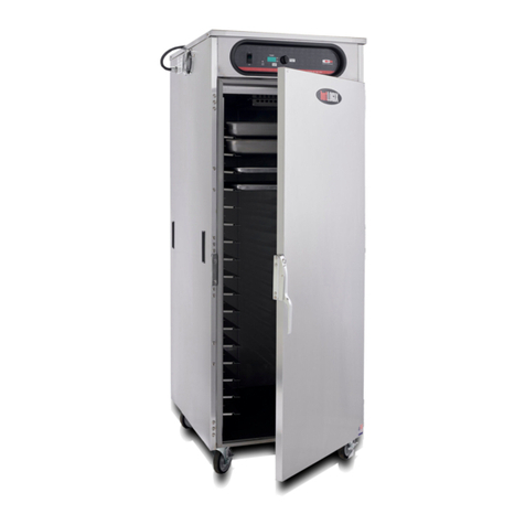
CARTER-HOFFMANN HL6 Series User manual

CARTER-HOFFMANN

CARTER-HOFFMANN HL6 Series User manual

CARTER-HOFFMANN HL5 Series Owner's manual

CARTER-HOFFMANN

CARTER-HOFFMANN HL5 Series Owner's manual

CARTER-HOFFMANN Logix6 Series User manual

CARTER-HOFFMANN

CARTER-HOFFMANN Logix6 Series User manual

CARTER-HOFFMANN VCNH3W2S User manual

CARTER-HOFFMANN

CARTER-HOFFMANN VCNH3W2S User manual

CARTER-HOFFMANN GardenChef GC42 User manual

CARTER-HOFFMANN

CARTER-HOFFMANN GardenChef GC42 User manual

CARTER-HOFFMANN VCNH212S-2T Owner's manual

CARTER-HOFFMANN

CARTER-HOFFMANN VCNH212S-2T Owner's manual

CARTER-HOFFMANN CD27 User manual

CARTER-HOFFMANN

CARTER-HOFFMANN CD27 User manual

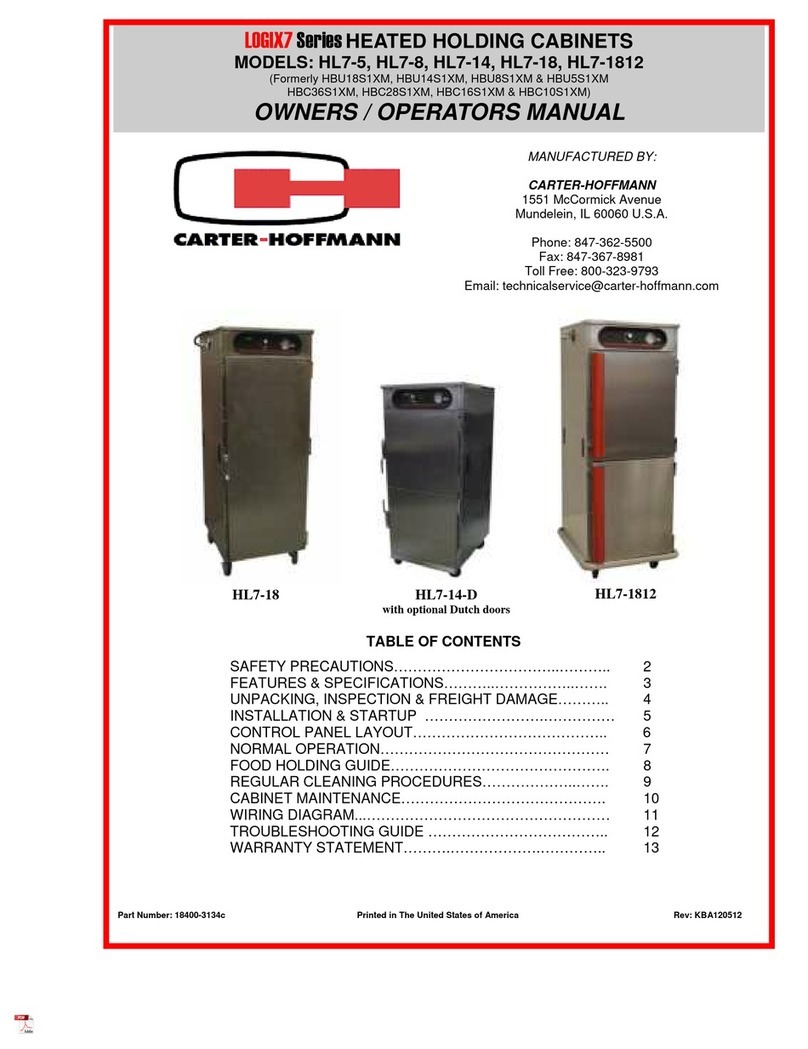
CARTER-HOFFMANN LOGIX7 Series User manual

CARTER-HOFFMANN

CARTER-HOFFMANN LOGIX7 Series User manual

CARTER-HOFFMANN PUCH-22 Owner's manual

CARTER-HOFFMANN

CARTER-HOFFMANN PUCH-22 Owner's manual

CARTER-HOFFMANN CRISP N HOLD User manual

CARTER-HOFFMANN

CARTER-HOFFMANN CRISP N HOLD User manual

CARTER-HOFFMANN HL8 Series User manual

CARTER-HOFFMANN

CARTER-HOFFMANN HL8 Series User manual

CARTER-HOFFMANN TC100 Owner's manual

CARTER-HOFFMANN

CARTER-HOFFMANN TC100 Owner's manual
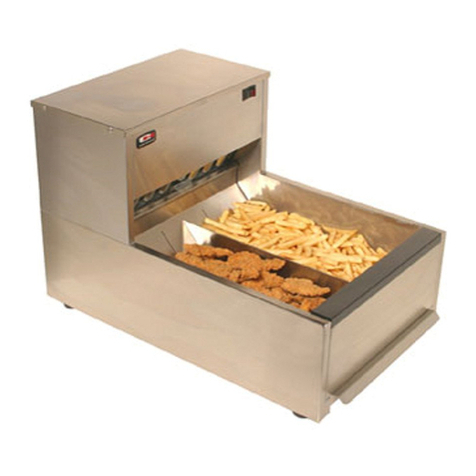
CARTER-HOFFMANN LOGIX9 Series Owner's manual

CARTER-HOFFMANN

CARTER-HOFFMANN LOGIX9 Series Owner's manual

CARTER-HOFFMANN HL9 Series Owner's manual

CARTER-HOFFMANN

CARTER-HOFFMANN HL9 Series Owner's manual

CARTER-HOFFMANN CW1 Owner's manual

CARTER-HOFFMANN

CARTER-HOFFMANN CW1 Owner's manual

CARTER-HOFFMANN PUCA-24S Owner's manual
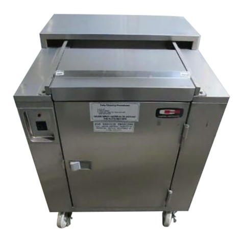
CARTER-HOFFMANN

CARTER-HOFFMANN PUCA-24S Owner's manual

Popular Commercial Food Equipment manuals by other brands

Varimixer V80 operating instructions

Varimixer

Varimixer V80 operating instructions

Bartscher 600 Series Installation, use and maintenance

Bartscher

Bartscher 600 Series Installation, use and maintenance

Frosty Factory 237A Service manual

Frosty Factory

Frosty Factory 237A Service manual

Beverage-Air MT06 Installation and operating instructions

Beverage-Air

Beverage-Air MT06 Installation and operating instructions

Silver King SKDC12-ESUS1 Technical manual

Silver King

Silver King SKDC12-ESUS1 Technical manual

Giorik GL720TGCT Installation, operation & maintenance manual

Giorik

Giorik GL720TGCT Installation, operation & maintenance manual

Inoksan PDG300 instruction manual

Inoksan

Inoksan PDG300 instruction manual

Zeybek T-120 operating instructions

Zeybek

Zeybek T-120 operating instructions

Bartscher 600 Series Installation, use and maintenance

Bartscher

Bartscher 600 Series Installation, use and maintenance

Duke ReadyFlex RFHU-23R Installation and operation manual

Duke

Duke ReadyFlex RFHU-23R Installation and operation manual

Diamond ENOTEC 340 Assembly, Installation and Use

Diamond

Diamond ENOTEC 340 Assembly, Installation and Use

Diamond N65/R212G-9G Installation, operating and maintenance manual

Diamond

Diamond N65/R212G-9G Installation, operating and maintenance manual

Fri-Jado Deli Multisserie Service manual

Fri-Jado

Fri-Jado Deli Multisserie Service manual

Eurocryor TWIN SV User instructions

Eurocryor

Eurocryor TWIN SV User instructions

STODDART Culinaire CH.IBSS.BMC.U.GSF.3 Specification, installation and operation manual

STODDART

STODDART Culinaire CH.IBSS.BMC.U.GSF.3 Specification, installation and operation manual

Patty-O-Matic Protege owner's manual

Patty-O-Matic

Patty-O-Matic Protege owner's manual

croydon FRG4 instruction manual

croydon

croydon FRG4 instruction manual

Fama 5 kg manual

Fama

Fama 5 kg manual

manuals.online logo
manuals.online logoBrands
  • About & Mission
  • Contact us
  • Privacy Policy
  • Terms and Conditions

Copyright 2025 Manuals.Online. All Rights Reserved.