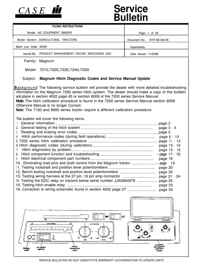
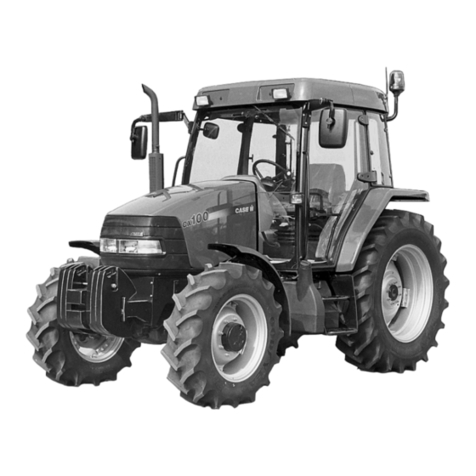
Case C50 User manual

r----------------------1
SERVICE MANUAL
TRACTORS
CS0, C60
C70, CBO
C90,C100
7-70900
1. Trim along dashed line.
2. Slide into pocket on Binder Spine.
TYPE 1·4
r----------------------1
SERVICE MANUAL
TRACTORS
CS0, C60
C70, CBO
C90,C100
7-70900
1. Trim along dashed line.
2. Slide into pocket on Binder Spine.
TYPE 1·4
r----------------------1
SERVICE MANUAL
TRACTORS
CS0, C60
C70, CBO
C90,C100
7-70900
1. Trim along dashed line.
2. Slide into pocket on Binder Spine.
TYPE 1-4
r----------------------1
SERVICE MANUAL
TRACTORS
CS0, C60
C70, CBO
C90,C100
7-70900
1. Trim along dashed line.
2. Slide into pocket on Binder Spine.
TYPE 1-4

cso, C60, C70, cao, C90 and c100 Tractors
Service Manual Don 7-70900
Table of Contents
Section
1 GENERAL
Loctite Product Chart
Safety Rules, General Information and Torque Specifications .................... 1001
General Specifications and Torques ........................................................... 1002
Special Tools ............................................................................................... 1005
2 REMOVAL AND INSTALLATION 200 l
4 ELECTRICAL
Electrical Troubleshooting and Schematics ................................................ .4001
5 STEERING
Steering Hand Pump ................................................................................... 5001
Steering Cylinder - 2WD Tractors ................................................................ 5002
Front Axle - 2WD Tractors ........................................................................... 5003
6 TRANSMISSION
Engine Clutch .............................................................................................. 6001
Separating the Tractor (Between Engine and Speed Transmission) ..........6002
Range Transmission Removal .................................................................... 6003
Speed Transmission Removal..................................................................... 6004
Speed Transmission Servicing .................................................................... 6005
Powershift Transmission ............................................................................. 6006
Range Transmission - MFD Tractors .......................................................... 6009
Rear Axle ..................................................................................................... 6012
Differential ................................................................................................... 6013
PTO ............................................................................................................. 6016
Shiftable PTO .............................................................................................. 6017
8 HYDRAULICS
Hydraulic Troubleshooting and Schematic .................................................. 8001
Hydraulic Hitch Adjustments ........................................................................ 8005
Multi Control Valve and Hydraulic Pump ..................................................... 8010
Unloading and Flow Control Valve .............................................................. 8015
Hydraulic Housing Servicing ........................................................................ 8035
Hydraulic Housing Removal ........................................................................ 8040
9 CHASSIS AND MOUNTED EQUIPMENT
Pedal, Lever and Switch Adjustment.. ......................................................... 9001
Seat Platform and Fenders .......................................................................... 9008
CASIE Don 7-70910
Pub. No.
8-98902
8-86531
7-70920
7-70930
7-70940
7-70960
7-70990
7-71290
7-72000
7-71000
7-71010
7-71020
7-71030
7-71040
7-71060
7-71140
7-71160
7-71180
7-71260
7-72010
7-71070
7-71080
7-72020
7-71300
7-71320
7-71340
7-71090
7-71100
IReprintedI
Copyright© 1997 Case Corporation
September 1997
Find manuals at https://best-manuals.com

1001-2
TABLE OF CONTENTS
SAFETY ................................................................................................................................................................. 3
GENERAL INFORMATION
Cleaning ............................................................................................................................................................. 5
Inspection ........................................................................................................................................................... 5
Bearing ............................................................................................................................................................... 5
Needle Bearings ................................................................................................................................................. 5
Gears ................................................................................................................................................................. 5
Oil Seals, O-Rings And Gaskets ........................................................................................................................ 5
Shafts ................................................................................................................................................................. 5
Service Parts ...................................................................................................................................................... 5
Lubrication .......................................................................................................................................................... 5
STANDARD TORQUE DATA FOR NUTS AND BOLTS
Chart 1 (Plain Nuts/Bolts) ................................................................................................................................... 6
Chart 2 (Phosphate Coated Nuts/Bolts) ............................................................................................................. 6
Chart 3 (Zinc or Cadmium Plated Nuts/Bolts) .................................................................................................... 7
Don 8-86530 Issued 3-96
Find manuals at https://best-manuals.com

1001-3
SAFETY
This symbol means ATTENTION! BECOME ALERT! YOUR SAFETY
IS INVOLVED. The message that follows the symbol contains
& important information about safety. Carefully read the message.
Make sure you fully understand the causes of possible injury or
death.
To prevent injury always follow the Warning,
Caution and Danger notes in this section and
throughout the manual.
Put the warning tag shown below on the key for the
key switch when servicing or repairing the machine.
One warning tag is supplied with each machine.
Additional tags Part Number 331-4614 are
available from your service parts supplier.
•
DONOT
OPERATE
Reason ___ _
•
See Other Side
c,s~ P;tro: "4o Pront'1:l In
USA
WARNING: Read the operators manual to
& familiarize yourself with the correct
control functions.
WARNING: Operate the machine and
~
equipment controls from the seat
~
position only. Any other method could
result in serious injury.
~
WARNING: This is one a man machine, no
~
riders allowed.
Don 8-86531
WARNING: Before starting engine, study
Operator's Manual safety messages.
Read all safety signs on machine. Clear
the area of other persons. Learn and
practice safe use of controls before
~
operating.
~
It is your responsibility to understand and
follow manufacturers instructions on
machine operation, service, and to
observe pertinent laws and regulations .
Operator's and Service Manuals may be
obtained from you J.J.Casedealer.
WARNING: If you wear clothing that is too
loose or do not use the correct safety
equipment for your job, you can be
& injured. Always wear clothing that will not
catch on objects. Extra safety equipment
• that can be required includes hard hat,
safety shoes, ear protection, eye or face
protection, heavy gloves and reflector
clothing.
WARNING: When working in the area of
~
the fan belt with the engine running, avoid
~
loose clothing if possible, and use
extreme caution.
WARNING: When doing checks and tests
~
on the equipment hydraulics, follow the
~
procedures as they are written. DO NOT
change the procedure.
WARNING: When putting the hydraulic
cylinders on this machine through the
& necessary cycles to check operation or to
remove air from a circuit, make sure all
people are out of the way.
Issued 3-96
Find manuals at https://best-manuals.com

1001-4
A_ WARNING: Use insulated gloves or
Lil
mittens when working with hot parts.
CAUTION: Lower all attachments to the
A.
ground or use stands to safely support
Lil
the attachments before you do any
maintenance or service.
CAUTION: Pin sized and smaller streams
of hydraulic oil under pressure can
penetrate the skin and result in serious
infection. If hydraulic oil under pressure
does penetrate the skin, seek medical
A.
treatment immediately. Maintain all hoses
Lil
and tubes in good condition. Make sure
all connections are tight. Make a
replacement of any tube or hose that is
damaged or thought to be damaged. DO
NOT use your hand to check for leaks,
use a piece of cardboard or wood.
CAUTION: When removing hardened pins
such as a pivot pin, or a hardened shaft,
Lh
use a soft head (brass or bronze) hammer
or use a driver made from brass or bronze
and a steel head hammer.
CAUTION: When using a hammer to
remove and install pivot pins or separate
parts using compressed air or using a
Lh
grinder, wear eye protection that
• completely encloses the eyes (approved
goggles or other approved eye
protectors).
CAUTION: Use suitable floor (service)
A.
jacks or chain hoist to raise wheels or
Lil
tracks off the floor. Always block machine
in place with suitable safety stands.
Don 8-86531
CAUTION: When servicing or repamng
the machine. Keep the shop floor and
A_ operator's compartment and steps free of
Lil
oil, water, grease, tools, etc. Use oil
absorbing material and or shop cloths as
required. Use safe practices at all times.
CAUTION: Some components of this
A_ machine are very heavy. Use suitable
Lil
lifting equipment or additional help as
instructed in this Service Manual.
DANGER: Engine exhaust fumes can
cause death. If it is necessary to start the
A_ engine in a closed place, remove the
Lil
exhaust fumes from the area with an
exhaust pipe extension. Open the doors
and get outside air into the area.
DANGER: When the battery electrolyte is
frozen, the battery can explode if (1), you
try to charge the battery, or (2), you try to
A_ jump start and run the engine. To prevent
Lil
that battery electrolyte from freezing, try
to keep the battery at full charge. If you do
not follow these instructions, you or
others in the area can be injured.
DANGER: Batteries contain acid and
explosive gas. Explosions can result
from sparks, flames or wrong cable
A_ connections. To connect the jumper
Lil
cables correctly to the battery of this
machine see the Operator's Manual.
Failure to follow these instructions can
cause serious injury or death.
Issued 3-96
Find manuals at https://best-manuals.com
1001-5
GENERAL INFORMATION
Cleaning
Clean all metal parts except bearings, in mineral
spirits or by steam cleaning. Do not use caustic
soda for steam cleaning. After cleaning dry and put
oil on all parts. Clean oil passages with compressed
air. Clean bearings in kerosene, dry the bearings
completely and put oil on the bearings.
Inspection
Check all parts when the parts are disassembled.
Replace all parts that have wear or damage. Small
scoring or grooves can be removed with a hone or
crocus cloth. Complete visual inspection for
indications of wear, pitting and the replacement of
parts necessary will prevent early failures.
Bearings
Check bearings for easy action. If bearings have a
loose fit or rough action replace the bearing. Wash
bearings with a good solvent or kerosene and
permit to air dry. DO NOT DRY BEARINGS WITH
COMPRESSED AIR.
Needle Bearings
Before you press needle bearings in a bore always
remove any metal protrusions in the bore or edge of
the bore. Before you press bearings into position
put petroleum jelly on the inside and outside
diameter of the bearings.
Don 8-86531
Gears
Check all gears for wear and damage. Replace
gear$ that have wear or damage.
Oil Seals, 0-Rings And Gaskets
Always install new oil seals, o-rings and gaskets.
Put petroleum jelly on seals and o-rings.
Shafts
Check all shafts that have wear or damage. Check
the bearing and oil seal surfaces of the shafts for
damage.
Service Parts
Always install genuine Case service parts, when
ordering refer to the Parts Catalog for the correct
part number of the genuine Case replacement
items. Failures due to the use of other than genuine
Case replacement parts are not covered by
warranty.
Lubrication
Only use the oils and lubricants specified in the
Operators or Service Manual. Failures due to the
use of non specified oils and lubricants are not
covered by warranty.
Issued 3-96
Find manuals at https://best-manuals.com

1001-6
STANDARD TORQUE DATA FOR NUTS AND BOLTS
NOTE: A "click type" torque wrench is recommended for the bolt torques listed below.
Chart 1 (Plain Nuts/Bolts)
BOLT TYPE 8.8 TYPE 10.9
SIZE MIN MAX MIN MAX
(mm) .__,.____
lb ft Nm lbft Nm lb ft Nm lb ft Nm
-· ·-·--
M4 3.0 4.0 3.4 4.5 4.3 5.8 4.8 6.5
MS 4.8 6.5 5.5 7.5 7.0 9.5 7.8 10.5
M6 8.2 11.0 9.2 12.5 11.8 16.0 13.3 18.0
--
MB 20.0 27.0 22.5 31.0 28.7 39.0 32.3 44.0
M10 40.0 54.0 45.0 61.0 56.0 77.0 64.0 87.0
M12 69.0 94.0 78.0 106.0 100.0 134.0 110.0 151.0
•-•--u , .._,_
M14 110.0 150.0 125.0 170.0 160.0 215.0 180.0 240.0
M16 175.0 235.0 190.0 260.0 245.0 335.0 275.0 375.0
M20 345.0 470.0 390.0 530.0 480.0 650.0 540.0 730.0
M22 475.0 640.0 530.0 720.0 655.0 890.0 735.0 1000.0
M24 600.0 810.0 675.0 915.0 830.0 1125.0 930.0 1265.0
M30 1190.0 1615.0 1340.0 1815.0 1645.0 2235.0 1855.0 2515.0
·---·
M36 2080.0 2825.0 2340.0 3175.0 2875.0 3900.0 3235.0 4390.0
·----- ·~--
Chart 2 (Phosphate Coated Nuts/Bolts)
BOLT TYPE 8.8 TYPE 10.9
SIZE MIN MAX MIN MAX
(mm) lb ft Nm lbft Nm lb ft Nm lb ft Nm
M4 2.3 3.0 2.6 3.4 3.2 4.4 3.6 4.9
MS 3.6 4.9 4.1 5.6 5.2 7.1 5.9 8.0
... --
M6 6.2 8.3 6.9 9.4 8.9 12.0 10.0 13.5
M8 15.0 20.3 16.9 23.3 21.5 29.2 24.2 32.8
M10 30.0 41.0 34.0 46.0 42.0 58.0 48.0 65.0
M12 52.0 71.0 59.0 80.0 75.0 101.0 83.0 113.0
M14 83.0 113.0 94.0 126.0 120.0 161.0 135.0 180.0
--
M16 131.0 176.0 143.0 195.0 185.0 251.0 205.0 280.0
M20 259.0 353.0 293.0 400.0 360.0 490.0 405.0 550.0
M22 355.0 480.0 400.0 540.0 490.0 665.0 550.0 750.0
M24 450.0 608.0 506.0 686.0 625.0 845.0 700.0 950.0
M30 893.0 1211.0 1005.0 1361.0 1235.0 1675.0 1390.0 1885.0
M36 1560.0 2119.0 1755.0 2381.0 2156.0 2925.0 2425.0 3295.0
·-
Don 8-86531 Issued 3-96
Find manuals at https://best-manuals.com

1001-7
Chart 3 (Zinc or Cadmium Plated Nuts/Bolts)
BOLT TYPE 8.8 TYPE 10.9
SIZE MIN MAX MIN MAX
(mm) lb ft Nm lb ft Nm lbft Nm lb ft Nm
M4 2.6 3.5 2.9 3.9 3.7 5.0 4.1 5.6
MS 4.1 5.6 4.6 6.3 5.9 8.0 6.6 9.0
M6 7.0 9.5 7.8 10.6 10.0 13.6 11.3 15.3
MS 17.0 23.1 19.1 25.9 24.4 33.1 27.4 37.2
M10 34.0 46.0 38.3 52.0 48.0 65.0 54.0 74.0
-·
M12 59.0 80.0 66.0 90.0 85.0 114.0 94.0 128.0
M14 94.0 128.0 106.0 145.0 136.0 183.0 153.0 205.0
M16 149.0 200.0 161.0 220.0 208.0 285.0 235.0 320.0
M20 293.0 400.0 330.0 450.0 408.0 555.0 460.0 620.0
M22 400.0 545.0 450.0 615.0 555.0 755.0 625.0 850.0
M24 510.0 690.0 575.0 780.0 705.0 955.0 790.0 1075.0
M30 1010.0 1375.0 1140.0 1545.0 1400.0 1900.0 1580.0 2140.0
~. M36 1770.0 2400.0 1990.0 2700.0 2445.0 3315.0 2750.0 3730.0
•·
Don 8-86531 Issued 3-96
Find manuals at https://best-manuals.com

Section
1002
GENERAL SPECIFICATIONS AND TORQUES
C50,C60,C70,C80,C90
and C100 Tractors
CASE UNITED KINGDOM LIMITED Don 7-70920 © 1997 Case Corporation
September 1997

1002-2
TABLE OF CONTENTS
GENERAL SPECIFICATIONS
Capacities ............................................................................................................................................................. 3
Steering Specifications .......................................................................................................................................... 3
Transmission Specifications .................................................................................................................................. 3
Hydraulic Specifications ........................................................................................................................................ 4
SPECIAL TORQUES
Steering ................................................................................................................................................................. 6
Transmission ......................................................................................................................................................... 6
Hydraulics ............................................................................................................................................................. 6
Don 7-70920 Issued 9-97

GENERAL SPECIFICATIONS
Capacities
TRANSMISSION/HYDRAULIC (HY-TRAN PLUS®) OIL CAPACITY
2WD Tractors ........................................................................................ 34 Litres
MFD Tractors ..................................................................................... 36.5 Litres
Steering Specifications
TRACK ADJUSTMENT
Toe-in .................................................................................................. 0 to 5 mm
Transmission Specifications
CLUTCH
C50/60/70 Tractors
1002-3
9.0 US gal
9.6 US gal
0 to 0.20 inch
Maximum Clutch Plate Thickness ......................................................... 10.4 mm 0.41 inch
Clutch Plate Diameter ............................................................................ 305 mm 12 inch
Number of Friction Plate Pads ............................................................................................................. 5 each side
CS0/90/100 Tractors
Maximum Clutch Plate Thickness ......................................................... 10.4 mm 0.41 inch
Clutch Plate Diameter ............................................................................ 310 mm 12.20 inch
Number of Friction Plate Pads ............................................................................................................. 7 each side
Pressure Plate and Friction Plate Spline Lubricant ............................................... MOLYKOTE D321R or equivalent
SPEED TRANSMISSION
Speed Transmission Rear Synchronizer End Play ................... 0.05 to 0.30 mm
Speed Transmission Front Synchronizer End Play................... 0.05 to 0.30 mm
RANGE TRANSMISSION
Pinion Bearing End Play (Maximum) ....................................................... 0.076 mm
Synchronizer Running Clearance ...................................................... 0.4 to 0.6 mm
Selector Fork Running Clearance
Standard Transmission .............................................................................. 0.45 mm
Forward/Reverse Transmission ................................................................. 0.05 mm
REAR AXLE
0.002 to 0.012 inch
0.002 to 0.012 inch
0.003 inch
0.016 to 0.024 inch
0.018 inch
0.002 inch
Planetary Gear/Planetary Gear Carrier Shimming .................................................................... refer to Section 6012
DIFFERENTIAL
Differential Lock Selector Ring Clearance (Engaged Position) ...0.025 to 0.90 mm
Ring Gear to Pinion Backlash .................................................... 0.152 to 0.304 mm
Ring Gear to Differential Housing Run-out ....................................... 0 to 0.102 mm
Differential Bearing Rolling Pull .......................................................... 2.0 to 6.5 kg
PTO CLUTCH
Standard Clutch
0.001 to 0.035 inch
0.006 to 0.012 inch
0 to 0.004 inch
4.5 to 14.5 lb
Number of Friction Plates...................................................................................................................................... 5
Number of Steel Separator Plates (2 between each Friction Plate)...................................................................... 8
Heavy Duty Clutch
Number of Friction Plates...................................................................................................................................... 6
Number of Steel Separator Plates......................................................................................................................... 5
Don 7-70920 Issued 9-97

1002-4
Hydraulic Specifications
HYDRAULIC PUMP
Hydraulic pump -
Standard capacity
CS0/60 C70/80/90/100
N/A 59 L/min
(15.6 US gpm)
Hydraulic pump - 62 L/min 540/750 PTO - 66 L/min (17.4 US gpm)
High capacity (16.4 US gpm) 540/1000 PTO - 68 L/min (18.0 US gpm)
Flow to Remotes - N/A 48 L/min
Standard capacity hydraulic pump (12.7 US gpm)
Flow to Remotes - 49 L/min 540/750 PTO - 55 L/min (14.2 US gpm)
High capacity hydraulic pump (12.9 US gpm) 540/1000 PTO - 57 L/min (15.0 US gpm)
Pump gear (No. of teeth) - 540/750 PTO - 19 teeth
Standard capacity hydraulic pump 540/1000 PTO - 23 teeth
Pump gear (No. of teeth) - N/A 540/750 PTO TYPE - 17 teeth
High capacity hydraulic pump 540/1000 PTO TYPE - 20 teeth
Pump mounting plate thickness - 5.31 to 5.43 mm
Standard capacity hydraulic pump (0.209 to 0.213 inch)
Pump mounting plate thickness - 7.86 to 7.98 mm
High capacity hydraulic pump (0.309 to 0.314 inch)
Steering Relief Valve Pressure ......................................................... 141 to 148 bar 2050 to 2150 psi
Pilot Relief Valve Pressure .......................................................................... 172 bar 2494 psi
Priority Flow Divider (Flow at all engine speeds)........................... 10.5 to 12 L/min 2.8 to 3.2 US gpm
Auxiliary Remote Detent Kick-out Pressure ............................... 144.7 to 172.3 bar 2100 to 2500 psi
Steering Relief Valve Pressure ......................................................... 141 to 148 bar 2050 to 2150 psi
Forward/Reverse Regulator Pressure ........................................................... 22 bar 320 psi
Powershift Regulator Pressure...................................................................... 22 bar 320 psi
MFD Regulator Pressure............................................................................... 22 bar 320 psi
PTO Pressure ....................................................................................... 15 to 17 bar 220 to 250 psi
Steering Regulator Return Flow .................................................... 10.5 to 12 L/min 2.8 to 3.2 US gpm
Oil Cooler Flow.............................................................................. 10.5 to 12 L/min 2.8 to 3.2 US gpm
Hydraulic Oil Type ..................................................................................................................... Case Hy-Tran® Plus
Hydraulic Oil Test Temperature ...................................................................... 49' C 120' F
FLOW DIVIDER SPRING
Free Length........................................................................................ 60.23 mm
PTO PRESSURE REGULATOR VALVE SPRING
Free Length........................................................................................ 45.44 mm
OIL COOLER/LUBRICATION SYSTEM BYPASS VALVE SPRING
Free Length........................................................................................ 48.00 mm
PTO CONTROL SPOOL ASSEMBLY
Heavy Duty Spring
Free Length.................................................................................... 37.77 mm
Light Duty Spring
Free Length.................................................................................... 46.99 mm
Return Spring
Free Length.................................................................................... 70.61 mm
UNLOADING VALVE SPRING
Free Length........................................................................................ 39.88 mm
Don 7-70920
2.37 inch
1.79 inch
1.88 inch
1.49 inch
1.85 inch
2.78 inch
1.57 inch
Issued 9-97

FLOW CONTROL VALVE SPRING
Free Length ........................................................................................ 43.18 mm
CHECK VALVE SPRING
Free Length ......................................................................................... 11.68 mm
ACTION (DROP RESPONSE) VALVE SPRING
Free Length ......................................................................................... 43.31 mm
DRAFT CONTROL VALVE
Draft Valve Spring
Free Length..................................................................................... 80.62 mm
Drop Valve Poppet Spring
Free Length..................................................................................... 38.74 mm
Drop Valve Spool Spring
Free Length..................................................................................... 23.37 mm
Don 7-70920
1002-5
1.70 inch
0.46 inch
1.70 inch
3.17 inch
1.52 inch
0.92 inch
Issued 9-97

1002-6
SPECIAL TORQUES
Steering
Steering Wheel Retaining Nut ............................................................. 45 to 51 Nm 33 to 37 lb ft
Steering Hand Pump Retaining Bolts .................................................. 45 to 51 Nm 33 to 37 lb ft
Steering Hand Pump End Cover Retaining Bolts ................................ 25 to 35 Nm 19 to 26 lb ft
Steering Cylinder Clevis (with Loctite 270) ....................................... 110to 135 Nm 80 to 100 lb ft
Steering Cylinder Clevis Pin Retaining Bolt......................................... 27 to 31 Nm 20 to 23 lb ft
Lower Bearing Carrier Retaining Bolts ............................................. 110to 122 Nm 80 to 90 lb ft
Steering Relief Valve Plug ................................................................... 40 to 60 Nm 30 to 44 lb ft
Front Weight Bracket Retaining Bolts.............................................. 481 to 542 Nm 355 to 400 lb ft
Steering Arm Clamp Bolt ................................................................. 108 to 122 Nm 80 to 90 lb ft
Front Wheel Nuts....................................................................... refer to Operators Manual for correct wheel rim size
Wheel Bearing Nut ...................................................................... refer to Operators Manual for tightening procedure
Tie Rod
Lock Nut .......................................................................................... 34 to 40 Nm
Lock Bolt ......................................................................................... 81 to 88 Nm
Tie Rod Tube Lock Nut................................................................ 235 to 250 Nm
Transmission
Flywheel Retaining Bolts ........................................................................... 105 Nm
Engine to Speed Transmission Mounting Bolts................................ 101 to 114 Nm
Speed to Range Transmission Retaining Bolts
5/8 inch Bolts (With Loctite 271) ............................................................ 230 Nm
1/2 inch Bolts (With Loctite 271) ............................................................. 110 Nm
Main Shaft Retaining Bolts .................................................................. 42 to 47 Nm
Selector Fork to Selector Rail Lock Bolt ............................................ 89 to 100 Nm
Selector Fork to Selector Rail Lock Nut............................................... 53 to 59 Nm
PTO Bearing Retainer Bolts (with Loctite 271) .................................... 42 to 47 Nm
Clutch Release Bearing Carrier Retaining Bolts (with Loctite 271) ..... 42 to 47 Nm
Pinion Shaft Retaining Bolts ................................................................ 45 to 50 Nm
Planet Carrier Retaining Bolt ........................................................... 290 to 330 Nm
Rear Axle Mounting Bolt.................................................................. 270 to 305 Nm
Rear Wheel Nuts
Flange Axle ................................................................................. 280 to 340 Nm
Bar Axle....................................................................................... 210 to 270 Nm
PTO Clutch Access Cover ................................................................ 117to 133 Nm
PTO Shaft Cover Retaining Bolts45 to 50 Nm33 to 37 lb ft
Top Link Sensing Bracket Cap Screws............................................ 285 to 312 Nm
PTO Clutch Access Cover Retaining Bolts....................................... 117to 133 Nm
PTO Housing
3/8 inch Retaining Bolts .................................................................. 45 to 50 Nm
1/2 inch Retaining Bolts .............................................................. 136 to 152 Nm
Hydraulics
Multi Control Valve Retaining Bolts ................................................... 45 to 50 Nm
Hydraulic Filter Retaining Bolt ........................................................... 16 to 21 Nm
Hydraulic Pump Retaining Bolts ........................................................ 24 to 28 Nm
Hydraulic Pump Drive Gear Locknut ................................................. 61 to 68 Nm
Hydraulic Pump End Plate
Retaining Bolt................................................................................. 27 to 31 Nm
Cap Screw...................................................................................... 24 to 27 Nm
Unloading and Flow Control Valve Retaining Bolts ......................... 44.7 to 50 Nm
Top Link Bracket Retaining Screws ................................................. 285 to 312 Nm
Lift Arm Retaining Bolt ................................................................ 133 to 149 Nm
Don 7-70920
25 to 30 lb ft
60 to 65 lb ft
173 to 184 lb ft
77 lb ft
75 to 84 lb ft
170 lb ft
81 lb ft
31 to 34 lb ft
65 to 74 lb ft
39 to 43 lb ft
31 to 34 lb ft
31 to 34 lb ft
33 to 37 lb ft
220 to 250 lb ft
200 to 225 lb ft
206 to 250 lb ft
155 to 200 lb ft
86 to 98 lb ft
210 to 230 lb ft
86 to 98 lb ft
33 to 37 lb ft
100 to 112 lb ft
33 to 37 lb ft
12 to 16 lb ft
18 to 21 lb ft
45 to 50 lb ft
20 to 23 lb ft
18 to 20 lb ft
33 to 37 lb ft
210 to 230 lb ft
98 to 110 lb ft
Issued 9-97

Section
1005
SPECIAL TOOLS
C50,C60,C70,C80,C90
and C100Tractors
CASE UNITED KINGDOM LIMITED
Don 7-70930 © 1997 Case Corporation
September 1997

1005-2 TABLE OF CONTENTS
SPECIAL TOOLS
ENGINE .............................................................................................................................................................. 3
FUEL ................................................................................................................................................................... 3
STEERING ......................................................................................................................................................... 3
TRANSMISSION ................................................................................................................................................ 3
HYDRAULICS .................................................................................................................................................... 4
Don 7-70930 Issued 9-97

TOOL APPLICATION
ENGINE
SPECIAL TOOLS
1005-3
TOOL PART NUMBER
Gauge, piston height, valve depth and cylinder liner protrusion................................................................. PD.41D
Seal Installer, Crankshaft Rear Oil Seal ................................................................................................... PD.145D
Timing Cover Aligning Tool....................................................................................................................... PD.1628
Engine Turn Over Tool ............................................................................................................................. PD.1658
Seal Installer, Timing Cover Seal (main tool) .............................................................................................. PD.170
Pressure Plate (use with PD.170) ............................................................................................................ PD.170-1
Sleeve (use with PD.170)......................................................................................................................... PD.170-2
Fastener Plate (use with PD.170) ............................................................................................................ PD.170-3
Adaptor (use with PD.170) ....................................................................................................................... PD.170-4
Crankshaft Locking Pin ............................................................................................................................... PD.241
FUEL
Timing Pin (Lucas Fuel Injection Pumps only) ............................................................................................ PD.246
ELECTRICAL
Multimeter ............................................................................................................................................... CAS1559
Signal Generator/Counter ...................................................................................................................... CAS2109
Harness Repair Kit ............................................................................................................................. AJl1400004
European only
Harness Repair Kit ....................................................................................................................... CAS31000
STEERING
Seal Installer, Danfoss Steering Hand Pump Seal .................................................................................. CAS2552
TRANSMISSION
Alignment Tools, Engine Clutch........................................................................................ CAS1918 and CAS1919
Tractor Splitting Stands
European
Tractor Splitting Kit ....................................................................................................................... CAS30009
North American
Tractor Splitting Stand (Front) ...................................................................................................... CAS10852
Tractor Splitting Stand (Rear) ....................................................................................................... CAS10853
Hydraulic Jacks .......................................................................................................................... CAS10855A
Seal Expander/Protector Set, Speed Transmission Mainshaft ............................................................... CAS2366
Seal Compressor, Speed Transmission Mainshaft ................................................................................. CAS2367
Alignment Tool, Powershift Clutch ......................................................................................................... CAS1921A
Don 7-70930 Issued 9-97
This manual suits for next models
5
Table of contents
Other Case Tractor manuals

Case
Case 180 User manual

Case
Case Puma 140 User manual

Case
Case OPTUM 270 CVT User manual

Case
Case FARMALL 110A Tier 4B User manual

Case
Case T9.435 Stage IV User manual

Case
Case STX Series User manual

Case
Case 448 User manual

Case
Case CVX 140 User manual

Case
Case JX70 User manual

Case
Case 9100 Series User manual

Case
Case JX 90 User manual

Case
Case 220 User manual

Case
Case JX95 HC User manual

Case
Case JX1060V User manual

Case
Case FARMALL 45C Tier 4B User manual

Case
Case JX60 User manual

Case
Case FARMALL 80N Tier 4A User manual

Case
Case 150-190 User manual

Case
Case 385 Diesel Install guide

Case
Case FARMALL 110A User manual