Case Magnum 7210 Reference manual

CASE
nir
Service
Bulletin
FILING INSTRUCTIONS
Binder: AG EQUIPMENT BINDER Page: 1 of 26
Binder Section: AGRICULTURAL TRACTORS Document No.: NTR SB 026 96
I
Mach
Loc
Code: 40000
Issued By: PRODUCT MANAGEMENT,
RACINE,
WISCONSIN, USA
Family: Magnum
Model:
7210,7220,7230,7240,7250
Supersedes:
Date Issued: 1
1/20/96
Subject:
Magnum Hitch Diagnostic Codes and Service Manual Update
Background The following service bulletin will provide the dealer with more detailed troubleshooting
nformation on the Magnum 7200 series hitch system. The dealer should make a copy of this bulletin
and
place in section 4002 page 45 or section 8009 of the 7200 series Service Manual.
Note: The hitch calibration procedure is found in the 7200 series Service Manual section 8009
Of
Service Manual is no longer Correct.
Note:
The 7100 and 8900 series tractor require a different calibration procedure.
This
bulletin will cover the following items.
1.
General information
...............................................................................................
page
2
2.
General testing of the hitch system
........................................................................
Reading and erasing error codes page
3
-
4
3.
...........................................................................
page
5
4.
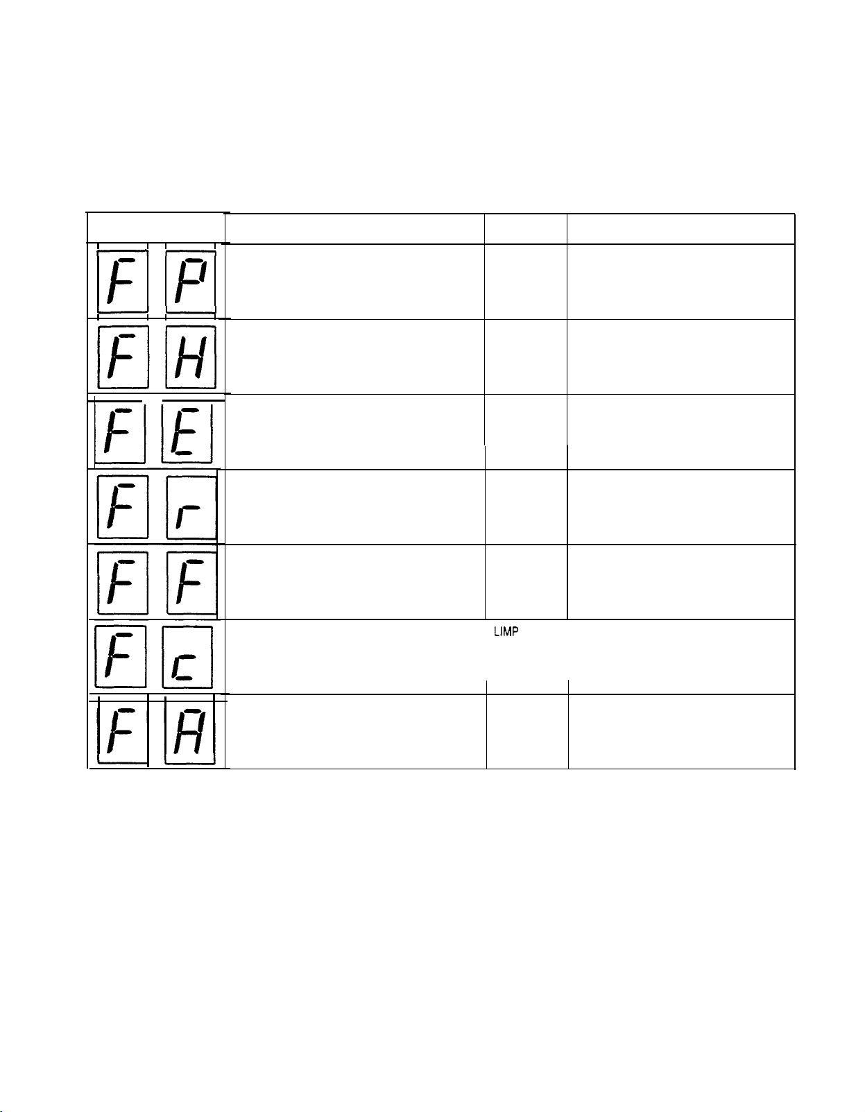
Hitch performance codes (during field operations)
................................................. page
6
-
10
5.
7200 series hitch calibration procedure
.................................................................
page
11
-
12
6.
Hitch diagnostic codes (during calibration)
.............................................................
7.
Hitch diagnostics by problem.. page 13
-
14
........
....................................................................... page
15
-
16
8.
Hitch component function and troubleshooting
....................................................
--page 17
-
18
9.
Hitch electrical component part numbers
...............................................................
page
19
10.. Eliminating load pins and draft control from the Magnum tractor
.........................
19
1
1. Testing rockshaft and position lever potentiometers
- - page
..............................................
20
12. Bench testing rockshaft and position lever potentiometers
page
....................................
20
13. Testing wiring harness at the 37 pin, 16 pin amp connector
page
.................................page 21
-
24
14.
Testing the EDC relay on tractors below serial number JJA0064978
....................
15. Testing hitch enable relay page 25
..................................................................................... page25
16. Correction to wiring schematic found in section 4002 page 27
.............................page26
SERVICE BULLETINS DO NOT CONSTITUTE WARRANTY AUTHORIZATION TO UPDATE UNITS

Service Bulletin NTR SB 026 96
Magnum Hitch Diagnostic Codes and Service Manual update
Page 2 of 26
GENERAL INFORMATION
The following items should not be over looked when troubleshooting the Magnum hitch system.
1.
A backwards
“c”
in the hitch diagnostic display means the control module is not calibrated.
Do not replace the control module, perform calibration.
2.
When reading and erasing error codes during calibration of the hitch control module, see page 5
of this bulletin, when “r.” appears on the diagnostic display. It will be followed by 102 or 200.
102
-
part number 112889A1
200
-
part number
232835A1,
after serial number JJA0067094
3. The EDC relay (number 6) has been eliminated on the Magnum tractors above serial number
JJA0064978 (electric PTO).Wire LB/529-18 (pin 14 of the 16 pin connector) is connected
directly to fuse number 7.
4.
5.
6.
7.
8.
9.
Loose position lever and rockshaft potentiometer shaft set screws will affect hitch performance
and may not show up as error codes.
The hitch must be
recalibrated
every time an hitch component is replaced or adjusted.
An empty hitch may move up slightly when the tractor is backed up if the load setting knob is set
below # 5. Set load knob above # 5.
Hitch enable indicator light should be lit when a error code is displayed. If not, the lamp is faulty.
The controller remote hitch switch error code is self correcting when the switch is released,
provided that the switch has not failed.
The hitch position lever must be cycled to recapture the hitch position when the tractor is started
and the rock shaft potentiometer and the position lever potentiometer are not within
4
2%
(
k
0.077 volts) of each other
(Enable light will be flashing).
10. The hitch position must be recaptured with the position lever after the hitch has been raised or
lowered with the remote hitch switch
(Enable light will be flashing).
11. The decimal point on the display should disappear when the tractor is moving faster than
.5
MPH.
If the decimal point in the display does not disappear when the tractor is moving
.5
MPH
or greater, the ground speed sensor or its circuit has failed.

Service Bulletin NTR SB 026 96
Magnum Hitch Diagnostic Codes and Set-vice Manual update
Page 3 of 26
General testing of the hitch system
STEP 1
Turn key “ON”.
The display on the hitch controller will do one of the following: A
-
D.
16 PIN
Connector
A. Display (blank), No enable light or diagnostic display at start up.
Check the electrical power and ground supply to the controller.
7200 series Tractors below serial number JJA0064978.
a.
Check battery and cab power stud (located on cab floor RH console).
b.
Fuse # 7 may be defective.
c
Turn key “ON” and check pin 14 of the 16 pin connector for power.
d.
Check pin 1 of the 16 pin connector for ground.
e.
Relay # 6 may be defective.
f.
Open circuit from EDC relay terminal 87 to control module (pin 14 in the 16 pin connector)
Other
a.
See electrical harness troubleshooting on page 23 for more information on power and
ground supply.
b. Control module may be defective.
7200 series Tractors above serial number JJA0064978.
a.
Check battery and cab power stud (located on cab floor RH console).
b.
Fuse
#
7 may be defective.
c.
Turn key “ON” and check pin 14 of the 16 pin connector for power.
d.
Bad ground to control module (pin 1 of the 16 pin connector). See page 23.
Other
a.
See electrical harness troubleshooting on page 23 for more information on power and
ground supply.
b. Control module may be defective.
B. No dash display, the Enable lamp works and the hitch operates correctly.
1. The diagnostic display is defective. Test by plugging in a another secondary panel.
2. The controller is defective.
C. Error code displayed.
Note Error codes must be corrected before going to step 2.
1. See hitch electrical performance codes pages 6
-
10
D. System normal
=
“8.” will appear for 2 seconds then the “0”.
1.
A display code of “0” indicates there are no electrical problems in the electronic hitch
system. This does not mean the hitch potentiometers are correctly adjusted.
Calibrate the hitch controller, see pages 11 and 12.
2. If the hitch does not work correctly and there are no error codes, the tractor’s hitch valve
and hydraulic system must be checked. Go to step 2.

Service Bulletin NTR SB 026 96
Magnum Hitch Diagnostic Codes and Service Manual update
Page 4 of 26
STEP 2
Testing
or lower
A.
B.
C.
STEP 3
tractor’s hydraulic system If there are no error codes and the hitch will not raise
check the following items to determine the cause of the problem.
Check regulated pressure, spec 280 psi at 1800 engine rpm.
-
If regulated pressure is in
spec
go to step B.
-
If regulated pressure is not in
spec
see Service Bulletin NTR SB 025 96 page 20.
for more information.
Check piston pump’s high pressure stand-by stetting.
-
Check high pressure stand-by 2650
-
2800 psi. (deadhead remote valve).
-
If high pressure stand-by pressure is in
spec.
go to step C.
-
If high pressure stand-by pressure is not in
spec,
see Service Bulletin NTR SB 025 96
for more information.
Check piston pump flow by flowrating 2nd remote valve, open flow control completely.
-
Check 2nd remote valve flow at 1500 psi.
(Spec.
2
-
22 GPM).
-
If the flow out the 2nd remote valve is greater than 20 gpm, go to step 3.
-
If the flow out the 2nd remote valve is not greater than 20 gpm. See Service Bulletin NTR
SB 025 96 for more information.
Electrically testing the hitch valve solenoid.
Disconnect the 16 pin connector from the hitch control module.
Test the hitch harness and solenoid resistance. Solenoid
spec.
3.8
-
4.2 ohms.
1. Raise solenoid
-
Connect multi meter across terminals pins 7 and 11.
2. Lower solenoid
-
Connect multi meter across terminals pins 7 and 15.
-
If solenoid is in
spec,
go to step 4.
-
If solenoid is not in
spec,
check wiring harness and solenoid. See page 24.
0
g!$$$l
10
m
0
,
14
*a
,*
,,
@@
16
PIN
Connector
00
a
s
.
J
STEP 4
Hydraulically testing the raise solenoid and the hitch valve.
Supply 12 volts to pin 7. Supply ground to pin 11 of the 16 pin connector (Do not ground to the
control module).Stand clear of the hitch and start the engine. Hitch should raise.
-
If hitch did not raise, the problem is with the solenoid plunger or hitch valve. See page 17.
-
If hitch raised correctly, the problem is not with the hitch valve. Go to step 5.
STEP 5
Hydraulically testing the lower solenoid and the hitch valve.
Supply 12 volts to pin 7 and ground to pin 15 of the 16 pin connector (Do not ground to the control
module). Stand clear of the hitch and start the engine, the hitch should lower.
-
If hitch did not lower, the problem is with the solenoid plunger or hitch valve. See page 17.
-
If hitch lowered correctly, the problem is not with the hitch valve.

Service Bulletin NTR SB 026 96
Magnum Hitch Diagnostic Codes and Service Manual update
Page 5 of 26
READING AND ERASING
ERROR CODES
Start engine while holding hitch
switch in down momentary
posi-
tion. Release switch when
q
appears.
[II
will appear now.
cl
r.
I
NOTE: To quit the error scan at any
time, toggle to UP position-toggle to
DOWN position. Repeat until
m
appears, procedure is finished.
111
.
I
Toggle to UP
position
B
will appear if no errors have
been recorded.
recorded, first code will appear now.
\A>
If any error codes have been
I
Toggle to UP position
Toggle to DOWN position
I
Down momentary
and release
I
cl
Next error code-
,-
Example only
.
Repeat down momentary and release
until
fl
or
B
appears.
-
Toggle to UP position
Toggle to DOWN position
I
Down momentary
and release Will
ill
repeat error scan
for second time.
I
Toggle to UP
position
I
I
Down
Toggle
to DOWN position momentary
and release
y
Finished
NOTE: Case Corporation reserves the
right
to make improvements in design or changes in
specifications
at any time without incurring any obligahon to
install
them on units
previously
sold.

Service Bulletin NTR SB 026 96
Magnum Hitch Diagnostic Codes and Service Manual update
Page 6 of 26
ELECTRONIC HITCH DIAGNOSTIC CODES
NORMAL OPERATION
A seven segment LED display will show codes that relate the performance of the Electronic Hitch Control
System. When the key switch is in the ON
position
power is applied to the Electronic Hitch Control System
and all display segments are displayed for 2 seconds for a display check.
The display code for normal operation is ‘0”. The dot
*.*
indicates tractor speed under 0.5 miles per hour.
HITCH CONTROL MODULE FAILURE MODES
The four non-normal failure modes corresponding to the various error code displays are, HALT, LIMP, DEGRADED 2, and
DEGRADED
1,
each failure mode will generate different modes of operation as follows:
MODE OPERATIONAL HITCH FUNCTIONS
HALT Hitch is totally disabled and no electrical actuation is possible.
LIMP Tractor travel must be stopped. The hitch can be momentarily actuated up and down from the RAISE/LOWER
switch or the rear remote switches.
DEGRADED 2
Hitch is operational in position mode only. Draft mode is inaccessible.
DEGRADED 1
Hitch is fully operational with default values for certain variables.
NOTE: When the display shows
the
failure code, the status lamp is on continuously or flashing.
BACKWARDS
“C”
IN DIAGNOSIS DISPLAY
Hitch control module not calibrated, calibrate hitch control module see page 11. Do not replace hitch
control module.

Service Bulletin NTR SB 026 96
Magnum Hitch Diagnostic Codes and Service Manual update
Page 7 of 26
These are the conditions (failures) that exist when the following codes are displayed. The codes are listed from the highest priority to
the lowest priority. When more than one failure exists simultaneously the highest priority failure will be displayed. All failures are
recorded in the controller (EEPROM) and can be retrieved in order of priority. See Reading and Erasing Error Codes.
CODE CAUSE MODE
SOLUTION
Open or short (to ground). Lower
coil
or lower coil
circuit failure.
HALT
S
hort to 12 volt. Lower coil or lower coil circuit
failure.
HALT
O
pen
or short (to ground). Raise coil or raise coil
circuit failure,
HALT
O
pen
or short (to ground) of the raise and lower
coi
HALT
coils or relay contacts are open. Raise and lower
coil
circuits failure, or relay circuit failed.
i
EEPROM
failure. The system cannot read
calibrated values or errors.
HALT
Tractor has not been calibrated. (Only appears
when
controller has been replaced)
HALT
Calibrate hitch controller.
1
Short to 12 volt, raise coil or raise coil circuit
failure.
I
HALT
Short to 12 volt, raise coil driver circuit.
HALT
Replace controller.
Short to 12 volt. lower coil driver.
HALT
Replace controller.
Error code when calibration time is expired or the
boards memory is bad.
HALT
Replace
coil.
Test wire harness for damaged wires or
connectors.
Replace
controller.
--
rest wire harness for damaged wires or
connectors.
Replace coil.
Replace
controller.
HI
Id
uu
Replace coil.
rest wire harness for damaged wires or
connectors.
Replace controller.
m3l
Replace relay.
Replace coil.
Test
wire harness for damaged wires or
connectors.
Replace controller.
--
Recalibrate controller.
Replace controller.
N
I-’
I-
--
/3(
i!
r-
Test wire harness for damaged wires or
connectors.
Replace coil.
Replace controller.
IHI
lb
Recalibrate controller.
Shut off key switch and restart tractor.
Replace controller

Service Bulletin NTR
SB
026 96
Magnum Hitch Diagnostic Codes and Service Manual update
Page 8 of 26
CODE
H
CAUSE
Open, shorted, or misadjusted hitch position
circuit.
MODE
LIMP
SOLUTION
Test
wire
harness for damaged wires or
connectors.
Replace position potentiometer.
Replace controller.
Open, shorted, or misadjusted position control
circuit. LIMP Test wire harness for damaged wires or
connectors.
Replace position potentiometer.
Replace controller.
Loss of 5 volt regulatorLIMP Replace controller.
I
I
Battery voltage less than 9.8 volts.
I
LIMP Test tractor battery circuit output.
Replace the controller if the “A “code occurs more than once on tractors
between SN:
JJA0067094
-
JJA0068206.
A good power and ground
supply to controller must be verified before
rep
lacing the controller.
El
Relay primary or contacts problem.
Watchdog circuit problem.
High battery supply voltage.
Upper limit circuit failed.
Load control circuit failure.
/5(
Both draft pin sensors failed or one draft pin
sensor failed when the tractor is configured for one
pm sensor.
I’
I
ml
Left pin sensor failed. The system will use the
other pin to operate
in
the draft mode.
El/
Right pin sensor failed. The system will use the
other pin to operate in draft mode.
!--I
LIMP Replace relay.
LIMP
1
Replace controller.
LIMP
1
Test tractor battery circuit output.
LIMP Test wire harness for damaged wires or
connectors.
DEGRADED Replace load control potentiometer.
2
Test wiring harness for damaged wires or
connectors.
Replace controller.
DEGRADED Replace one or both draft pin sensors.
2
Test wire harness for damaged wires or
connectors.
DEGRADED Replace the left draft pin sensor.
1
Test wire harness for damaged wires or
connectors.
Replace the right draft pin sensor.
Test
wire
harness for damaged wires or

Service Bulletin NTR SB 026 96
Magnum Hitch Diagnostic Codes and Service Manual update
Page 9 of 26
ELECTRONIC HITCH PERFORMANCE CODE
r-
CODE
C
H
1
P
t
MODE SOLUTION
DEGRADEDReplace RAISE/LOWER switch.
AUSE
litch RAISE/LOWER switch circuit failed. If the
roblem IS intermittent the function is disabled until
he
next engine startup.
est
wire harness for damaged wires or
connectors.
T
Hitch drop speed circuit failure. Drop speed will be
set
to mid-range. Maximum drop rate can be
achieved
by
using
the LOWER MOMENTARY
position on the RAISE/LOWER switch.
DEGRADED
1
Replace the drop speed potentiometer.
Test
wire harness for damaged wires or
connectors.
Hitch
response speed circuit failure. DEGRADED
Replace
the hitch response speed
1
potentiomer.
Test
wire harness for damaged wires or
connectors.
7
Hitch
travel circuit failure. Travel will be set to DEGRADED
naximum.
1
Replace the hitch travel speed
potentiometer.
rest wire harness for damaged wires or
connectors.
4
Lamp circuit failure. DEGRADED
1
Replace lamp.
lest
wires
to lamp for damaged wires or
connectors.
DEGRADED
1
Capture the hitch and lower the hitch.Hitch position is above the upper limit. Hitch can
be lowered by the control lever or by the rear
remote switches.
Rear remote switches failure when:
1.
The remotes are operated simultaneously.
2. A remote switch is operated before startup.
3.
A remote switch is operated when the hitch is
against the lower travel limit.
4
Remote switch LOWER is activated when the
hitch is against the lower travel limit.
5
Remote switch RAISE is activated when the
hitch is against the upper travel limit.
DEGRADED Error code will stop when switch is
1
reieased.
3
LOWER MOMENTARY failure when:
1. LOWER MOMENTARY switch is operated
before startup.
2. LOWER MOMENTARY switch is operated with
the tractor in motion.
3. LOWER MOMENTARY switch is operated
when the hitch is against the lower travel limit.
DEGRADED Error code will stop when switch is
1
released.
Display circuit failure. Test secondary panel
with one from another tractor

Service Bulletin NTR SB 026 96
Magnum Hitch Diagnostic Codes and Service Manual update
Page 10 of 26
ELECTRONIC HITCH PERFORMANCE CODE
NOTE: When the RAISE/LOWER
switch
and a second signal have failed the hitch can only be operated through the rear remote switches
The following failure codes will appear:
CODE
--
f
P
-1
CAUSE MODE
RAISE/LOWER
switch and position sensor failure. LIMP
SOLUTION
Replace RAISE/LOWER switch and:
Test position sensor wire harness.
Replace position potentiometer.
Replace controller.
RAISE/LOWER switch and position control failure.
LIMP
Replace RAISE/LOWER
switch
and:
Test position sensor wire harness.
Replace posrtion potentiometer.
Replace controller.
RAISE/LOWER switch failure and high battery
voltage.
LIMP
Replace RAISE/LOWER switch and test
tractor battery circuit output.
RAISE/LOWER switch and 5 volt regulator failure.
LIMP
Replace RAISE/LOWER switch and
controller.
RAISE/LOWER switch and relay failure.
LIMP
Replace RAISE/LOWER
switch
and relay.
RAISE/LOWER switch failure and low battery
voltage.
LIMP
Replace RAISE/LOWER
switch
and test
tractor battery circuit output.
RAISE/LOWER switch and watchdog circuit
failure. Replace RAISE/LOWER switch and
j
LlMP
/
controller.
II

Service Bulletin
NTF? SB 026 96
Magnum Hitch Diagnostic Codes and Service Manual update
Page 11
of
26
7200
SERIES HITCH CALIBRATION PROCEDURE
All components and harnesses must be in good working order prior to calibration.
.
.
.
.
1.
2.
3.
4.
5.
6.
7.
8.
The position control potentiometer must be set to 4.85
+
0.1 volts DC when the position control
lever is at its maximum height.
Before starting the calibration process, make sure that the hitch is free to move all the way
between the cylinder’s minimum and maximum limits with no load. Make sure that no
interference exists during the movement and the back of the tractor is clear of all objects.
Calibration cannot be performed while the tractor is moving.
Calibration must be performed without a load.
Install CAS 1638 test box with CAS 1897 adapter harness (black) per the Service Manual section 8009
page 4. CAS 1638 test box slide switch should be in the ON position.
Only center the hitch, if error code indicates that the hitch valve (null) is not centered, see page 13 for error
codes. To center hitch valve, see Service Manual section 8009 pages 4 though 7. If hitch Null adjustment
tool CAS 2028 is used a +5 setting is acceptable. Disregard All Null tool error codes (7200 series tractors
only).
Record and clear any error codes prior to adjustment. See reading and erasing error codes on page 5 of this
bulletin.
With the ignition switch in the ON position, place the hitch position lever in the FULLY RAISED,
TRANSPORT position and the test box at position
1,
set D.C. voltage to 4.85 +
.1
volts. Adjust the hitch
position pot in the console if needed. See Service Manual 8009
-
8 steps 16-21.
Test position pot:
Set
the DVM to the 2 decimal place range, do not perform test with
the DVM in the auto
ranging mode. Move the position lever forward though the range, the voltage should smoothly drop to
approximately 1.4 volts D.C. in the fully lowered position. When moving the position lever rearward toward
the transport position the voltage should smoothly increase back to its original 4.85 volts D.C. once the
transport position is reached.
-
If the voltage does not return to its original 4.85 volts D.C. or the voltage is intermittent, replace the
potentiometer.
-
If the voltage goes to
“0”
or above 4.85 volts, replace the potentiometer.
With the position lever fully rearward (transport position), start the engine while holding the hitch switch in the
MOMENTARY position. Release the switch when the letter
“r”
appears in the diagnostic display.
“C” will appear in the diagnostic display if there are no failures that will prevent calibration.If “C” does not
appear, See reading and erasing error codes on page 5 of this bulletin.
Note: If a
“g”
appears during calibration, the draft pins or its wiring circuit is failed.
Note: In some cases a “g” may appear in the display. The hitch control module is asking “does the system
have two load sensing pins
?”
Answer yes by pressing the hitch switch to the momentary position then
release. Normally the control module will sense two pin and not ask. See page 19 for more
information.
Press the hitch switch to the MOMENTARY position and release,“c” should appear on the diagnostic
display.

Service Bulletin
NTR
SB 026 96
Magnum Hitch Diagnostic Codes and Service Manual update
Page 12 of 26
HITCH CALIBRATION PROCEDURE CONTINUED
9. Press the hitch switch to the MOMENTARY position and release.“11” should appear on the diagnostic
10.
11.
12.
13.
display. Note: The control module is asking you if the tractor has an upper limit knob.
Press the hitch switch to the MOMENTARY position and release to answer “yes”. A “8” should appear on
the diagnostic display. Note: The “8” means the system is ready to calibrate.
Hold the hitch switch in the MOMENTARY position until the hitch has completely lowered, then release.
Do not release switch before hitch is fully lowered. A “6” should appear on the diagnostic display.
With the hitch in the FULLY LOWERED position and the test box at position 2, set D.C. voltage to
.9
+
.1
volts, at the hitch rockshaft pot above the right rear axle housing. See Service Manual section
8009-9
steps
24
&
25.
Test Rockshaft pot: Set the DVM to the 2 decimal place range, do not perform test with the DVM in the
auto ranging mode. View the DVM voltage while the hitch is being raised in step 16. As the hitch raises the
voltage should smoothly increase from
.9
+
.1
to approximately 4.70
+
.2
volts D.C. in the fully raised
position.
14. Move the hitch lever to the full raise position. Raise the hitch by pressing the hitch switch to the
MOMENTARY position and releasing the switch (The hitch position lever should still be in the transport
position). A “9” should appear on the diagnostic display. The hitch should raise after a delay. If any reason
occurs where the hitch movement should be stopped during this process, toggle the switch to the UP
position.
15. Move the hitch position lever to the fully lowered position. Make sure the stop is not in the way. The lever
must be all the way down.
16. Test Rockshaft pot: Set the DVM to the 2 decimal place range, do not perform test with the DVM in the
auto ranging mode. View the DVM voltage while the hitch is being lowered in step 19. As the hitch lowers
the voltage should smoothly decrease from 4.70 +
.2
to approximately to
.9
+
.1
volts D.C. in the fully
lowered position.
17.
18.
19.
Lower the hitch by pressing the hitch switch to the MOMENTARY position and release. After a delay, the
hitch will lower to full down. A “U” should appear on the diagnostic display. If any reason occurs for the
hitch movement to be stopped during the process, toggle the hitch switch to the UP position.
When the hitch has fully lowered, press the hitch switch to the MOMENTARY position and release. “0”
should appear on the diagnostic display, meaning calibration has been successful.
Check for and clear any error codes from memory.
SEE PAGE 20 FOR INFORMATION ON TESTING THE ROCKSHAFT AND
POSITION LEVER POTENTIOMETERS

Service Bulletin NTR SB 026 96
Magnum Hitch Diagnostic Codes and Service Manual update
Page 13 of 26
HITCH DIAGNOSTIC CODE DURING CALIBRATION
A seven segment LED display will show codes that relate to
the performance of the Electronic Hitch Control system during
calibration. The one digit display will flash alternately from H
to failure code symbol. Note that there may be two types of
failures involved with the calibration process:
1. Unique system failures such as ‘hitch is not at maximum”,
or “command lever is not at minimum”.
2. Components failures, which are essential for the
calibration process.
In all cases, the calibration process will be aborted and the
hitch will transition into a HALT mode where hitch motion
cannot proceed. However, failures which are system failures
will be displayed using the codes in this document whereas
component failures will be displayed using the usual
operational diagnostic codes. Failures that exist during
calibration but are not essential to the calibration process, will
not cause any discontinuation of the calibration and will be
displayed using the usual operational diagnostic codes.
The following explains the conditions (failures) that exist
in
the system when the following codes are displayed.
NOTE: An error code means there is a problem with the
component or some part of the circuit. Example: Loose
connection, bad wire, faulty component, etc.
CALIBRATION TROUBLESHOOTING CHART
NOTE:
All
letter
"H"
codes
will
halt
calibration.
Position
command is not at
maximum.
Raise PWM (Pulse Width
Modulation) threshold is above
55%.
Raise PWM (Pulse Width
Modulation) threshold is below
4%.
Full raise current detection
(100%
Pulse With Modulation) is
out of range.
Hitch Position IS not all the way
up.
SYMBOL
H
.
I-
.
m-l
u
..
alI2
l
.
HIT
.
.
RlEl
I
l
’
POSSIBLE CAUSES
SOLUTIONS
A
Lever is not at maximum.
B
Position command
potentiometer
IS
bad.
C
Position
lever command is not set at
4.75 to 4.95 volts maximum.
D
Position command potentiometer shaft
is loose from lever.
A
Move lever to maximum.
B
Replace position command
potentiometer.
C
Adjust position lever.
D
Tighten the lever onto the
potentiometer shaft.
A
Coil resistance is very high.
B
Raise driver does not connect to
coil.
C
Battery voltage IS very low or power to
coils is disconnected.
D
Valve raise portion is stuck closed.
E
Hitch valve null out of adjustment..
A Replace coil.
B
Test wire harness for continuity.
C
Test tractor battery circuit output.
D
Repair or replace hitch control
valve.
A
Coil resistance is very low.
B
Battery voltage is very high.
C Valve failure.
D
Hitch valve null out of adjustment.
E
Center the hitch valve.
A Replace coil.
B
Test tractor battery circuit output.
C
Repair or replace hitch control
valve.
A
Battery voltage too high.
B
Raise coil resistance
too
low.
D
Center the hitch valve.
A
Test tractor battery
circuit
output.
B
Replace coil.
A
Interference prevents hitch from
moving up.
B
Position potentiometer failed.
C
Position potentiometer is loose from
the lever.
D
Position
potentiometer
out of
adjustmert.
A
Remove obstruction from hitch.
B
Replace position potentiometer.
C
Tighten
the lever onto the
potentiomer shaft.
D
Adjust position potentiometer.

Service Bulletin NTR SB 026 96
Magnum Hitch Diagnostic Codes and Service Manual update
Page 14 of 26
PROBLEM
Position command lever is not at
minimum
Lower
PWM
threshold is above 5536.
Lower PWM threshold is below 4%.
Calibration time expired.
Hitch position is not at minimum.
Hitch position range is not within
limits.
A scaling factor between position
command and hitch position is not
within limits
Wrong draft pm connected when
operating on one pin.
SYMBOL
HIM
4
Position
command lever is not at
A
Move lever to minimum.
minimum.
..
3
Position command potentiometer
3
Replace position command
failed. potentiometer.
C
Position command potentiometer
C
Tighten
the lever onto the
shaftIS loose from lever. potentiometer shaft.
D
Position
command potentiomer out
D
Adjust position command
of adjustment.potentiometer.
-I
HE
A
Coil
resistance is very high. A Replace coil.
B
Lower driver does not connect to
B
Test wire harness for continuity.
.
-0
coil.
C
Battery voltage is very low or power
C
Test tractor battery circuit output.
to coils is disconnected.
D
Valve lower portion is stuck closed.
D
Repair or replace hitch control
Hitch valve null out of adjustment. valve.
i
m-
A
Coil
resistance is very low. A Replace coil.
0
B
Battery voltage is very high.
B
Test tractor battery circuit output.
. .
Hitch valve null out of
adjustment..
C Valve failure.
C
Repair or replace hitch control
valve.
Md
A
Operator did not acknowledge A Recalibrate.
1
(within 6 minutes) when hitch is at
.
.
the bottom when display is ‘u’.
BID
A
Hitch position lever is not at AMove hitch position lever to
minimum. minimum or remove obstruction
.
4
from hitch.
B
Replace position potentiometer.
i
B
Position
potentiometer failed.
C
Adjust position potentiometer.
C
Position potentiometer is not set per
0.9 to 1.1 volts at minimum.
1
--
IUL
A
AReplace position potentiometer.
n
Position potentiometer failed.
B
Position potentiometer shaft is
loose B
Tighten
the lever onto the
.
from lever. potentiometer shaft.
~C Hitch travel restricted.
C
Remove obstruction from hitch.
q
lr
A
Position or position command or AReplace position or position
both potentiometers failed. command or both potentiometers.
.
B
Position or position command or
B
Tighten the levers on the
both potentionmeters shafts are
loose
potentiometer shafts.
from lever.
1
4
A
Left side draft pin connected instead ARemove wire harness from left
of the right side. side draft pin and connect
to
the
right side.
SOLUTIONS
J
POSSIBLE CAUSES
NOTE:
All
calibration failures
will
result in HALT
condition. You must correct the problem. restart the
engine and start calibration again.

Service Bulletin NTR SB 026 96
Magnum Hitch Diagnostic Codes and Service Manual update
Page 15 of 26
1.
Hitch will not fully raise or fully lower
A.
Check hitch diagnostic display for error code after start up.
B. The position control lever potentiometer is out of adjustment. See hitch calibration p
11.
C.
The hitch rockshaft potentiometer is out of adjustment. See hitch calibration p 11.
D.
The valve is not centered correctly. See hitch calibration p
11.
Note: The above problems require that the hitch be calibrated.
Note: A display code of
"0"
indicates there are no electrical problem in the electronic hitch
system. This does not mean the hitch potentiometers are correctly adjusted.
2.
Hitch will not raise the load
A. Perform Electronic Hitch Control troubleshooting (Troubleshooting hitch system page 4).
1. Is regulated pressure in
spec.
?
2. Is low pressure standby in
spec.
?
3. Is the 2nd remote valve flow and pressure in
spec.
?
4. Is the 1st remote valve causing the PFC pump to remain on high pressure ?
5. Load on the hitch is beyond rated capacity.
6. The hitch valve pilot spool is sticking.
7, The hitch valve control spool is sticking.
8. Cushion relief valve is missing or leaking.
9.
High pressure stand-by not in
spec.
3.
Hitch will not lower
A.
B.
C.
D.
E.
F.
Perform Electronic Hitch Control troubleshooting (Troubleshooting hitch system page 4).
Hitch drop speed control set incorrectly for the load on the hitch.Increase drop speed
setting.
Up/Down switch in the up position. Move the UP/Down switch to the down position.
Load control is set between position 1 and 5 and tractor is moving greater than
.5
mph
Increase the load setting.
Lockout plunger spool in hitch valve is sticking.
Hitch mechanically locked-up.
4.
Hitch lowers slightly when starting and stopping the tractor engine.
Note: Hitch will not enable on start
-
up if the engine is turn off and restarted.
A. Hitch valve not centered correctly or hitch has a cylinder leak.
5.
Hitch raises slightly when starting and stopping the tractor engine.
Note: Hitch will not enable on start
-
up if the engine is turn off and restarted.
A. Hitch valve not centered correctly.
B. Hitch has a cylinder leak.
6.
Hitch hiccups (engine running)
A. Leak in hitch cylinders. See page item 9.
7.
Hitch operates normally except when the position control lever is placed into the transport
position. Hitch will then creep up until bottomed out against rear lid and the hydraulic system will
then go to high pressure standby.
A. Hitch not calibrated correctly. Re-calibrate hitch. See page 11.
HITCH DIAGNOSTICS BY PROBLEM

Service Bulletin NTR SB 026 96
Magnum Hitch Diagnostic Codes and Service Manual update
Page 16 of 26
HITCH DIAGNOSTICS BY PROBLEM
8. Hitch raises slowly
A. 1st remote valve is causing PFC pump to operate at high pressure stand by or is using all
the PFC pumps hydraulic flow. Remember the 1st remote has priority over hitch and
remotes valve 2 though 4.
1. See Service Bulletin NTR SB 022 96 using and understanding the 1st remote valve.
2. Operate equipment with 2nd remote valve.
3. Remove restriction from implement hydraulic supply line or valve.
4. Use tractor’s remote valve flow control to control flow to implement valve.
9. Hitch leaks down (engine off)
A.
B.
Isolate the hitch lift assist cylinders from the main rock shaft cylinder to determine if the lift
assist cylinder is leaking.
1. Lower hitch and cap off lift assist cylinder supply line.
2. Place load (weight) on the hitch and raise hitch. Turn tractor engine off.
If hitch does not leak down the problem is with the assist cylinder.
If hitch leaks still leaks down go to step B.
Testing the hitch rockshaft cylinder and the cushion relief valve.
1.
2.
3.
4.
5.
Lower the hitch completely.
Disconnect the hitch supply line to the rockshaft at the hitch valve.
Connect the hitch rockshaft cylinder supply line to remote valve “B” port.
Cap the hitch valve supply port.
Start the engine and use the remote valve to raise the hitch with sufficient weight to cause
leak down.
6.
Put remote valve in neutral and close the shut off valve.
to remote valve
If the hitch leaks down the problem is in the rock shaft cylinder area.
A.
B.
C.
Check cushion relief valve per the service manual section 8010 page 10 step 17.
Cylinder piston seal leaking. Order seal kit
230318A1
per service bulletin NTR SB
077 96 issued March 25 1996. DO NOT INSTALL SEAL BACKWARDS see bulletin
for installation information.
Seal ring P.N. 1957863C1 between hitch cover and cylinder crushed or fell out
during assembly.
Make sure seal does not fall out during installation of
cylinder to cover.
If the hitch does not leak down the problem is with the hitch valve.
A. Hitch valve lock check poppet or o-ring is leaking.
B. Hitch valve lock out spool is scored/sticking.

Service Bulletin NTR SB 026 96
Magnum Hitch Diagnostic Codes and Service Manual update
Page 17 of 26
1.
.
.
.
2.
.
.
HITCH VALVE COMPONENTS AND FUNCTION
PILOT
PRESSURE
INLET
LEVER
LOCK CHECK
SPRING
PLUNGER
SPOOL
Hitch valve solenoid
Moves the solenoid plunger.
TO LUBE
The solenoid plunger must be adjusted (centered) to prevent the hitch from drifting up or down
when the solenoid is not powered. The solenoid plunger controls the hitch valve pilot spool.
Raise
-
The solenoid plunger shifts to the right to raise the hitch.
Lower
-
The solenoid plunger shifts to the left to lower the hitch.
Spec:
Pin A to pin C ---- 3.8
-
4.2 OHMS
Pin B to pin C ---- 3.8
-
4.2 OHMS
-
If the plunger in the solenoid valve is off center to the right, the hitch will drift up.
-
If the plunger in the solenoid valve is off center to the left, the hitch will drift down.
-
If the plunger sticks, the hitch may be slow to respond or continue to drift when the up /down
switch is released.
Pilot spool
Raise
-
Once the pilot spool is shifted to the right, it then directs regulated pressure to the left end
of the control spool. The control spool shifts right to raise the hitch.
Lower
-
Once the pilot spool is shifted to the left it then directs regulated pressure to the right end
of the control spool. The control spool shifts left to lower the hitch.
-
If the pilot spool sticks to the right, the hitch will drift up.
-
If the pilot spool sticks to the left, the hitch will drift down.

Service Bulletin NTR SB 026 96
Magnum Hitch Diagnostic Codes and Service Manual update
Page 18 of 26
3.
.
.
4.
.
.
5.
.
6.
HITCH VALVE COMPONENTS AND FUNCTION CONTINUED
Control spool
Raise
-
Once the control spool is shifted to the right it then directs PFC pump pressure to the left
end of the lockout plunger spool (the lockout spool dose not move) but the pressure in that area
will unseat the load check poppet to raise the hitch.
Lower
-
Once The control spool is shifted to the left it then directs PFC pump oil to the right end
of the lockout plunger spool which (unseats) pushes the lock check poppet to the left to lower the
hitch.
-
If the control spool stick in the center position the hitch won’t raise or lower.
-
if the control spool sticks to the left, the hitch will drift down.
-
If the control spool sticks to the right, the hitch will drift up.
Lockout plunger spool
Raise
-
The lockout plunger spool is not shifted or moved with oil pressure when the hitch is
raised. The piston pump oil pressure at the left end of the spool will unseat the load check poppet
to raise the hitch.
Lower
-
The lockout plunger is shifted to the left with piston pump pressure. The lockout spool
pushes the load check poppet to the left to lower the hitch.
-
If the lockout plunger spool sticks to the right, the hitch won’t lower.
-
If the lockout plunger spool sticks to the left the hitch will settle.
Load check poppet
The load check poppet prevents the hitch from settling when the engine is turned “off” or when
the hitch valve is in neutral (solenoid not powered by hitch control module).
The load check plunger must shift to the left for the hitch to raise or lower.
-
If the load check poppet sticks to the left the hitch will settle.
Signal check valve
The hitch signal check valve isolate the piston pump signal circuit from the Steering valve, remote
valves and the power beyond valve. The PFC pump pressure will be set by the valve producing
the highest signal pressure.

Service Bulletin NTR SB 026 96
Magnum Hitch Diagnostic Codes and Service Manual update
Page 19 of 26
7200 SERIES ELECTRONIC HITCH COMPONENTS
Control Module
Up/Down rocker switch
Enable replacement bulb
Position control lever potentiometer 1000 ohms
+
10% resistance pins A to C.
Hitch rockshaft position potentiometer 1000 ohms
+
10% resistance pins A to C.
Mechanical travel (rotation)
Load control potentiometer in cab 10,000 ohms
+
10%
Hitch travel potentiometer in cab 10,000 ohms
+
10%
112885A2
113663A1
781991C1
114255A2
114255A2
360 degrees
A186061
A186061
Secondary panel
Response potentiometer 10,000 ohms
2
10% pins A to C
Drop rate potentiometer 10,000 ohms
+
10% pins A to C
Upper limit potentiometer 10,000 ohms
+
10% pins A to C
Diagnostic display (will not work on 7100 series)
235010A1
ELIMINATING DRAFT CONTROL FROM THE MAGNUM TRACTOR
Load pins (draft control) can be eliminated from the tractor by simply unplugging the draft pins and
reprogramming the hitch controller. See page 11 step 7 of the Calibration procedure for Electronic
Hitch. Cover connector ends if draft pins are removed.
Note: If a
"g"
appears during calibration, the draft pins or its wiring circuit has failed,
Note: During calibration a “g” may appear in the diagnostic display. The hitch control module is
asking “Does the system have two load sensing pins?”
Answer no if the load pins are disconnected by pressing the hitch switch to the up position and then
to the down position (not to the down momentary position).
Answer yes if draft control is desired and the load pins are connected by pressing the hitch switch to
the momentary position then releasing. Normally, the control module will sense two pin and not
ask.

Service Bulletin NTR SB 026 96
Magnum Hitch Diagnostic Codes and Service Manual update
Page 20 of 26
TESTING ROCKSHAFT AND POSITION LEVER POTENTIOMETERS
Position potentiometer Use the CAS
-
1638 test box in position 1 with CAS 1897 adapter harness (black).
Set the DVM to the 2 decimal place range, do not perform test with the DVM in the auto ranging mode. Move
the position lever forward though the range, the voltage should smoothly drop to approximately 1.4 +
.2
volts
D.C. in the fully lowered position. When moving the position lever rearward toward the transport position the
voltage should smoothly increase back to its original 4.85
+
.1
volts D.C. once the transport position is reached.
Rockshaft potentiometer Use the CAS
-
1638 in position 2 with the CAS 1897 adapter harness (black). Set
the DVM to the 2 decimal place range, do not perform test with the DVM in the auto ranging mode. View the
DVM voltage while raising and lowering the hitch. As the hitch lowers the voltage should smoothly decrease
from approximately 4.6 to approximately to
.9
+
.1
volts D.C. in the fully lowered position.
Note: To completely lower the hitch the up/down switch must be double clicked and held in the momentary
position.
Note: The over all range of the rockshaft pot is slightly reduced from the calibration procedure. this is due to the
hitch control module stopping the hitch movement just before it reaches the mechanical travel limits as it does
during calibration.
BENCH TESTING
STEP
1
ROCKSHAFT
&
POSITION LEVER POTENTIOMETERS
STEP 3
Connect the multimeter test leads between the
cen-
ter (sense) terminal and the opposite
outside
terminal. Rotate the potentiometer through its
working range This reading must also be
smooth
and continuous
Connect the multimeter test leads to each outside
terminal of the potentiometer. Set the multimeter to
the 2K ohm
scale.
Measure the total resistance
across the potentiometer. the total resistance value
must be 900 to
1100
ohms. If this value cannot be
obtained, the potentiometer must be replaced.
STEP 2
Connect the multimeter test leads to the center
(sense) terminal and one of the outside terminals.
Locate and turn the pot through its full
working
range. The multimeter reading must be smooth and
continuous through the full working range.
This manual suits for next models
4
Table of contents
Other Case Tractor manuals

Case
Case JX1060V User manual

Case
Case MXM120 User manual

Case
Case 9100 Series User manual

Case
Case MX Series User manual

Case
Case 220 User manual

Case
Case CVX 140 User manual

Case
Case FARMALL 45C Tier 4B User manual

Case
Case 220 User manual

Case
Case OPTUM 270 CVT User manual

Case
Case Farmall 115C User manual