manuals.online logo
Brands
  1. Home
  2. •
  3. Brands
  4. •
  5. Cateye
  6. •
  7. Bicycle Accessories
  8. •
  9. Cateye STRADA User manual

Cateye STRADA User manual

AC
MENU
MODE
4
6
9
8
5
2
1
3
7
MENUMENU
MODEMODE
MENUMENU
MODEMODE MODEMODE
MODEMODE
Tire circumference
reference table
12 x 1.75
14 x 1.50
14 x 1.75
16 x 1.50
16 x 1.75
18 x 1.50
18 x 1.75
20 x 1.75
20 x 1-3/8
22 x 1-3/8
22 x 1-1/2
24 x 1
24 x 3/4
Tubular
24 x 1-1/8
24 x 1-1/4
24 x 1.75
24 x 2.00
24 x 2.125
26 x 7/8
26 x 1(59)
26 x 1(65)
26 x 1.25
26 x 1-1/8
26 x 1-3/8
26 x 1-1/2
26 x 1.40
26 x 1.50
26 x 1.75
26 x 1.95
26 x 2.00
26 x 2.10
26 x 2.125
26 x 2.35
26 x 3.00
27 x 1
27 x 1-1/8
27 x 1-1/4
27 x 1-3/8
650 x 20C
650 x 23C
650 x 35A
650 x 38A
650 x 38B
700 x 18C
700 x 19C
700 x 20C
700 x 23C
700 x 25C
700 x 28C
700 x 30C
700 x 32C
700C Tubular
700 x 35C
700 x 38C
700 x 40C
29 x 2.1
29 x 2.3
935
1020
1055
1185
1195
1340
1350
1515
1615
1770
1785
1753
1785
1795
1905
1890
1925
1965
1920
1913
1952
1953
1970
2068
2100
2005
2010
2023
2050
2055
2068
2070
2083
2170
2145
2155
2161
2169
1938
1944
2090
2125
2105
2070
2080
2086
2096
2105
2136
2146
2155
2130
2168
2180
2200
2288
2326
Tire size L (mm)
MENUMENU
MODEMODE
L mm
21
2
1
8
8
6
5
3
9
3
4
4
3
5 mm
3
2
1
4
4 5
Measure wheel
circumference (L) of
your bike
To get the most accurate
calibration do a wheel roll
out. With the valve stem
perpendicular to the ground,
mark the pavement at the
valve stem. With the riders
weight on the bike, roll the
wheel one tire revolution in a
straight line and mark the
ground when the valve stem
is perpendicular to the
ground again. Measure the
distance in millimeters. This
is the most accurate wheel
calibration number.
Switch the
screen or
move digits
(by pressing
& holding)
Enter the tire circumference
Enter the tire circumference of your bicycle in
mm.
* Refer to the tire circumference reference table.
Pull securely
1
2
3
4
km/h ↔mph
Increase Move digits
(by pressing
& holding)
Register the
setting
Register
the setting
Clear all data (initialization)
Press the AC button on the back.
Select the desired speed units
Select “ ” or “ ”.
How to install the unit on your bicycle
Sensor line
Inside of right
front fork
Stem
Handlebar
Inside of right
front fork
Inside of right
front fork
*Attach between one and three sensor pads 7,
putting them together as required.
24h ↔12h,
or increase
the value
Register
the
setting
(finish)
To the sensor
Cut
Set the clock
When MODE is pressed and held, “Displayed
time”, “Hour”, and “Minute” will appear, in
this order.
When attaching the bracket to the handlebar
Caution:
Tighten the bracket, ensuring that the
cable does not get caught in the stem.
Caution:
Tighten the bracket, ensuring that the cable
does not get caught in the handlebar.
B
The clearance between the sensor surface
and the magnet must not exceed 5mm.
Attach the bracket to the stem or handlebar
When attaching the bracket to the stem
Wrap the cable around
the front brake cable
Caution:
Turn the handlebar to
make sure wire does
not hinder full rotation. Caution:
Round off the cut edge of the
bracket band to prevent injury.
Install the sensor and magnet :
A
The magnet should pass
through the sensor line.
Install the sensor
1Bracket band
2Bracket
3Sensor
4Magnet
5Sensor rubber band (x2)
6Sensor hook
7Sensor rubber pad (x3)
8Bracket rubber pad
9Nylon ties (x5)
: Speed unit
: Wheel size icon
AC
Remove/install the computer
Holding the unit
Push outward
Spoke
Preparing the computer
*After installation, rotate the front wheel gently to check that the speed is displayed on the
computer. If the speed is not displayed, check that conditions
A
and
B
are satisfied.
Toward the sensor line
WARNING / CAUTION
•Do not concentrate on the computer while riding. Ride safely!
•Install the magnet, sensor, and bracket securely. Check these periodically.
•If a child swallows a battery, consult a doctor immediately.
•Avoid having the computer in direct sunlight for unnecessary or extended periods.
•Do not disassemble the computer.
•Do not drop the computer. Doing so may result in a computer malfunction or damage.
•When using the computer installed on the bracket, change the MODE by pressing on the
three dots below the screen. Pressing hard on other areas can result in malfunction or
damage to the computer.
•Never place the computer on a metal surface. If you do, the contact points will conduct
electricity, discharging the battery.
•Tighten the dial on the Flex-Tight bracket by hand only. Over-tightening can damage the
bracket threads.
•When cleaning the computer, bracket and sensor, do not use thinners, benzene, or
alcohol.
•Dispose of used batteries according to local regulations.
•LCD screen may be distorted when viewed through polarized sunglass lenses.
Battery case cover
Contact
*You can also use ties 9(in place of sensor rubber
band 5) to secure the sensor.
Install the magnet
Click
Push!
When the computer is
mounted on the bracket
CATEYE STRADA
CYCLOCOMPUTER CC-RD100
U.S. Pat. Nos. 5236759/6957926 Pat./Design Pat. Pending
Copyright© 2006 CATEYE Co., Ltd.
CCRD10-061114 066600501 3
ENG
MODE
MODE
MODE MODE MODE MODE
MODEMODE
MENUMENU
CC-RD100
Wheel selection ..... Toggle between the specified wheel size (tire circumference)
and . Use this function if the computer is to be shared
between two bicycles.
Pressing MODE toggles between and .
Wheel size entry .... Pressing MODE increases the value, and pressing and
holding MODE moves to the next digit.
* To enter the wheel size , display using “Wheel selection”.
Clock setting .......... To set the clock, refer to “Preparing the computer-4”.
Total distance manual entry
................................ Before reinitializing the computer, note the total distance. This
reading will later allow you to enter the total distance
manually. Pressing MODE increases the value, and pressing
and holding MODE moves to the next digit.
Speed unit .............. Pressing MODE toggles between and .
Maintenance
To clean the computer or accessories, use diluted neutral detergent on a soft cloth,
and wipe it off with a dry cloth.
Replacing the battery
If the display appears faded, replace the battery.
Install a new lithium battery (CR1620) with the (+) side
facing upward. Then reinitialize the computer referring
to “Preparing the computer”.
Caution: When closing the battery case cover, make
sure that the rubber packing is properly seated
to ensure that a waterproof seal is maintained.
* A precision screwdriver is required to replace the battery.
*1 With the computer installed on the
bracket, press on the three raised dots on
the face of the computer.
*2 If Tm exceeds approximately 27 hours or
Dst exceeds 999.99 km, .E (Error) is
displayed as the average speed. Reset data.
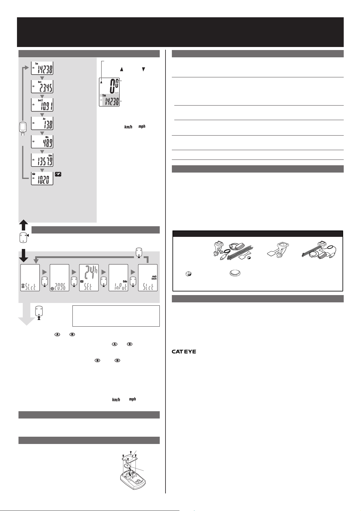
Pace arrow
Indicates whether the current speed
is faster ( ) or slower ( ) than the
average speed.
Tm Elapsed Time
0:00’00” - 9:59’59”
Dst Trip Distance
0.00 - 999.99 km [mile]
Dst
2
Trip Distance-2
0.00 - 999.99 /
1000.0 - 9999.9 km [mile]
Av Average Speed*2
0.0 - 200.0 km/h
[0.0 - 125.0 mph]
Mx Maximum Speed
0.0(4.0) - 200.0 km/h
[0.0(3.0) - 125.0 mph]
Odo Total Distance
0.0 - 9999.9 /
10000 - 99999 km [mile]
Clock
0:00 - 23:59
or 1:00 - 12:59
CR1620
Rubber packing (rear side)
Wheel
selection
Wheel size
entry
Clock setting Total distance
manual entry
Speed unit
Setting change
(by pressing &
holding)
*After changing, be sure to press MENU to register
the setting.
*If the menu screen is not touched for a minute, the
Measuring screen reappears without data changes.
Starting/Stopping measurement
Measurements occur automatically
when the bicycle is in use. During
measurement, or flashes.
Switching computer function
Pressing MODE switches function,
in order, as shown on the left.
Resetting data
To reset measurement data, display
any data other than for Dst-2 and then
press and hold MODE. Pressing and
holding MODE with Dst-2 displayed
resets Dst-2 only.
The total distance is never reset.
Power-saving function
If the computer has not received
any signal for an hour, power-
saving mode will activate and only
the clock will be displayed.
Alternatively, if the sensor detects a
signal or MODE is pressed, the main
display reappears.
Changing the computer settings [menu screen]
To bring up the menu screen, press MENU in any mode.
Each time MODE is pressed, the relevant menu screen appears. Pressing and
holding MODE changes the setting of the displayed menu.
*1
Current speed
0.0(4.0) - 200.0 km
[0.0(3.0) - 125.0 mph]
Selected Mode
Operating the computer [Measuring screen] Troubleshooting
MODE does not work when the computer is mounted on its bracket.
Check that there is no dirt between the bracket and the computer.
Wash off the bracket with water to get rid of any dirt, and to ensure that the computer slides in and out
smoothly.
Speed and distance are not displayed. (Touch a metal item against two contact points of the computer
several times to create a short circuit while observing the display. If a numeric value appears, this signifies
that the computer is functioning normally.)
Is the clearance between the sensor and magnet too great? (must be
≤
5 mm)
Does the magnet pass through the sensor line?
Adjust the positions of the magnet and sensor.
Is there any foreign matter (which would prevent a clean contact) on the contact points of the computer
and/or bracket?
Clean the contact points.
Check that no wire cable is worn or broken. Even with a normal appearance, it may be that a wire cable
could be broken internally.
Replace the bracket sensor set.
No display.
Is battery in the computer run down?
Replace it. Then reinitialize the computer referring to “Preparing the computer”.
Incorrect data appear.
Reinitialize the computer referring to “Preparing the computer”.
Specification
Battery ...................................... Lithium battery (CR1620) x 1
Battery life ................................ Approx. 3 years (Using the battery one hour a day; the battery life will vary with the
conditions of use.)
Controller .................................. 4-bite, 1-chip microcomputer (Crystal controlled oscillator)
Display ...................................... Liquid crystal display
Sensor ...................................... No contact magnetic sensor
Wheel circumference range ..... 0100 mm - 3999 mm (Default figure A: 2096 mm, B: 2096 mm)
Working temperature ............... 32 °F - 104 °F (0 °C - 40 °C) (This product will not function appropriately when exceeding the
Working Temperature range. Slow response or black LCD at lower or higher temperature
may happen respectively.)
Dimensions/weight ................... 1-53/64” x 1-7/32” x 19/32” (46.5 x 31 x 15 mm) / 0.63 oz (18 g)
* The factory-loaded battery life might be shorter than the above-mentioned specification.
* The specifications and design are subject to change without notice.
#160-0290
Parts kit
#160-0291
Rear long cable
#160-0280
Bracket band
#160-0270
Bracket/Sensor
#169-9691
Wheel magnet
#169-6180
Lithium battery (CR1620)
Standard Parts
LIMITED WARRANTY
2-Year Computer only
(Accessories/Bracket sensor and Battery Consumption excluded)
CatEye cycle computers are warranted to be free of defects from materials and workmanship for a period of two years
from original purchase. If the product fails to work due to normal use, CatEye will repair or replace the defect at no
charge. Service must be performed by CatEye or an authorized retailer.
To return the product, pack it carefully and enclose the warranty certificate (proof or purchase) with instruction for
repair. Please write or type your name and address clearly on the warranty certificate.
Insurance, handling and transportation charges to CatEye shall be borne by person desiring service.
For UK and REPUBLIC OF IRELAND consumers, please return to the place of purchase. This does not affect your statutory
rights.
CO., LTD.
2-8-25, Kuwazu, Higashi Sumiyoshi-ku, Osaka 546-0041 Japan
Attn: CATEYE Customer Service Section
Service & Research Address for USA
CATEYE Service and Research Center
1705 14th St. 115 Boulder, CO 80302
Phone: 303.443.4595
Toll Free: 800.5CATEYE
Fax: 303.473.0006
E-mail: [email protected]
URL: http://www.cateye.com

Other manuals for STRADA

2

This manual suits for next models

1

Other Cateye Bicycle Accessories manuals

Cateye STRADA CC-RD100N User manual

Cateye

Cateye STRADA CC-RD100N User manual

Cateye Micro CC-6000 User manual

Cateye

Cateye Micro CC-6000 User manual

Cateye CC-MC100W User manual

Cateye

Cateye CC-MC100W User manual

Cateye CC-PA100W User manual

Cateye

Cateye CC-PA100W User manual

Cateye HL-EL120 User manual

Cateye

Cateye HL-EL120 User manual

Cateye Vectra CC-7000 User manual

Cateye

Cateye Vectra CC-7000 User manual

Cateye CC-VL510 User manual

Cateye

Cateye CC-VL510 User manual

Cateye Adventure CCAT2W-110930 User manual

Cateye

Cateye Adventure CCAT2W-110930 User manual

Cateye CC-AT200W User manual

Cateye

Cateye CC-AT200W User manual

Cateye ENDURO 2 User manual

Cateye

Cateye ENDURO 2 User manual

Cateye CC-VT100W User manual

Cateye

Cateye CC-VT100W User manual

Cateye Padrone Smart + CC-SC100B Guide

Cateye

Cateye Padrone Smart + CC-SC100B Guide

Cateye MSC 2DX Instruction manual

Cateye

Cateye MSC 2DX Instruction manual

Cateye CC-PA100W User manual

Cateye

Cateye CC-PA100W User manual

Cateye CC-TR100 User manual

Cateye

Cateye CC-TR100 User manual

Cateye CC-MT400 User manual

Cateye

Cateye CC-MT400 User manual

Cateye TR200DW280P User manual

Cateye

Cateye TR200DW280P User manual

Cateye CC-DU100 User manual

Cateye

Cateye CC-DU100 User manual

Cateye HL-1600 User manual

Cateye

Cateye HL-1600 User manual

Cateye CC-CL100 User manual

Cateye

Cateye CC-CL100 User manual

Cateye Enduro8 CC-ED300 Setup guide

Cateye

Cateye Enduro8 CC-ED300 Setup guide

Cateye V3 - Instruction manual

Cateye

Cateye V3 - Instruction manual

Cateye GVolt70.1 HL-EL552G-RC User manual

Cateye

Cateye GVolt70.1 HL-EL552G-RC User manual

Cateye Tomo CC ST-200 User manual

Cateye

Cateye Tomo CC ST-200 User manual

Popular Bicycle Accessories manuals by other brands

CYCLITE SKI RACK / 02 Instructions for use

CYCLITE

CYCLITE SKI RACK / 02 Instructions for use

Evobike JBT03K manual

Evobike

Evobike JBT03K manual

DNA PROTECTED DL305-B user guide

DNA PROTECTED

DNA PROTECTED DL305-B user guide

Busch+Müller IXBACK senso instruction manual

Busch+Müller

Busch+Müller IXBACK senso instruction manual

Vestil BR-M3 Series instruction manual

Vestil

Vestil BR-M3 Series instruction manual

BAFANG BT F15.655.C Dealer's manual

BAFANG

BAFANG BT F15.655.C Dealer's manual

Exposure Lights SIX PACK MK9 Sync user guide

Exposure Lights

Exposure Lights SIX PACK MK9 Sync user guide

Trixie 12805 instructions

Trixie

Trixie 12805 instructions

strex SP219 user manual

strex

strex SP219 user manual

Contec 800 manual

Contec

Contec 800 manual

Strend Pro 2170272A quick start guide

Strend Pro

Strend Pro 2170272A quick start guide

4iiii BKM4G user guide

4iiii

4iiii BKM4G user guide

Bosch BDU280P CX owner's manual

Bosch

Bosch BDU280P CX owner's manual

Bikehut 151657 instructions

Bikehut

Bikehut 151657 instructions

Trelock FC 510 Instructions for mounting and use

Trelock

Trelock FC 510 Instructions for mounting and use

Shimano TIAGRA RD-4500 user manual

Shimano

Shimano TIAGRA RD-4500 user manual

Bobike Go Maxi Carrier Assembly instructions

Bobike

Bobike Go Maxi Carrier Assembly instructions

Specialized Speedzone Sport CR2032 user manual

Specialized

Specialized Speedzone Sport CR2032 user manual

manuals.online logo
manuals.online logoBrands
  • About & Mission
  • Contact us
  • Privacy Policy
  • Terms and Conditions

Copyright 2025 Manuals.Online. All Rights Reserved.