manuals.online logo
Brands
  1. Home
  2. •
  3. Brands
  4. •
  5. Caviblaster
  6. •
  7. Cleaning Equipment
  8. •
  9. Caviblaster 0625-G Manual

Caviblaster 0625-G Manual

Other Caviblaster Cleaning Equipment manuals

Caviblaster 0520-E Manual

Caviblaster

Caviblaster 0520-E Manual

Caviblaster 1325-G Manual

Caviblaster

Caviblaster 1325-G Manual

Caviblaster 0520-G Manual

Caviblaster

Caviblaster 0520-G Manual

Caviblaster 1725-G Manual

Caviblaster

Caviblaster 1725-G Manual

Caviblaster 2828-E Manual

Caviblaster

Caviblaster 2828-E Manual

Popular Cleaning Equipment manuals by other brands

Skov Farm AirClean Technical user guide

Skov

Skov Farm AirClean Technical user guide

Nilfisk-Advance CA 240 operating instructions

Nilfisk-Advance

Nilfisk-Advance CA 240 operating instructions

ORBOT LiO operating manual

ORBOT

ORBOT LiO operating manual

unGer OmniClean Assembly instructions

unGer

unGer OmniClean Assembly instructions

CENTREGO Toucan Eco Bio Carry user manual

CENTREGO

CENTREGO Toucan Eco Bio Carry user manual

BANDELIN SONOREX TECHNIK RM 110 UH Instructions for use

BANDELIN

BANDELIN SONOREX TECHNIK RM 110 UH Instructions for use

Sealey VMA913 instructions

Sealey

Sealey VMA913 instructions

Aztec 520-00 owner's manual

Aztec

Aztec 520-00 owner's manual

BÖWE P25 installation instructions

BÖWE

BÖWE P25 installation instructions

Tunap MF 929 Service information

Tunap

Tunap MF 929 Service information

RIDGID K-45AF-7 manual

RIDGID

RIDGID K-45AF-7 manual

Aircraft POWERGLIDE manual

Aircraft

Aircraft POWERGLIDE manual

Suevia 130.5011 EASYCLEANER Mounting instructions

Suevia

Suevia 130.5011 EASYCLEANER Mounting instructions

i-MO Öko 2000 user guide

i-MO

i-MO Öko 2000 user guide

unGer Hydro Power Ultra UNP01 operating instructions

unGer

unGer Hydro Power Ultra UNP01 operating instructions

Black & Decker BHPC130 Original instructions

Black & Decker

Black & Decker BHPC130 Original instructions

Uni-ram UG5000E operating manual

Uni-ram

Uni-ram UG5000E operating manual

Axi MTC HC-300 Installation, operating and maintenance manual

Axi

Axi MTC HC-300 Installation, operating and maintenance manual

manuals.online logo
manuals.online logoBrands
  • About & Mission
  • Contact us
  • Privacy Policy
  • Terms and Conditions

Copyright 2025 Manuals.Online. All Rights Reserved.

Operation &
Maintenance
Manual
Model 0625-G
Model 0625-G –Manual
Operating Instructions
WARNING: To ensure operator safety and efficient operation of the
CaviBlaster®, it is essential to follow these instructions.
Preparing the CaviBlaster system for operation:
1. Inspect the CaviBlaster® power unit, hose and gun for any signs of damage.
2. Inspect Inlet Strainer (Figure-1) to ensure that it is not dirty or clogged. Clean as
necessary.
Water Inlet - Figure #1
3. Check lubricating oil(s) and fuel levels: Assure proper oil level in engine
crankcase, pressure pump and fuel level in fuel tank (gasoline). Figures 2, 3, 4.
Engine Oil Level - Figure #2
Pump Oil Level - Figure #3 Fuel Level - Figure #4
4. Fill lubricating oil(s) to proper level(s) in the pressure pump (Yellow cap on
pump) (Figure-5) and engine (Yellow cap on head cover) (Figure-6) per
manufacturers’ operating manuals.
Pump Oil Yellow Cap - Figure #5 Yellow Cap on head cover - Figure #6
NOTE: Pressure Pump Oil (SAE 30W-Non-Detergent) Figure-7; Engine Oil (SAE 10W 30) Figure-8
Pressure Pump Oil - Figure #7 Engine Oil - Figure #8
5. To provide water to the Model 0625-G CaviBlaster® power unit, connect feed
pump to the water inlet connection on the power unit (Figure-9).
Connect Feed Pump to Water Inlet - Figure #9
Inspect inlet connection (Figure-10) to ensure that it is not clogged. Clean if
necessary
Connect Feed Pump to Water Inlet - Figure #10
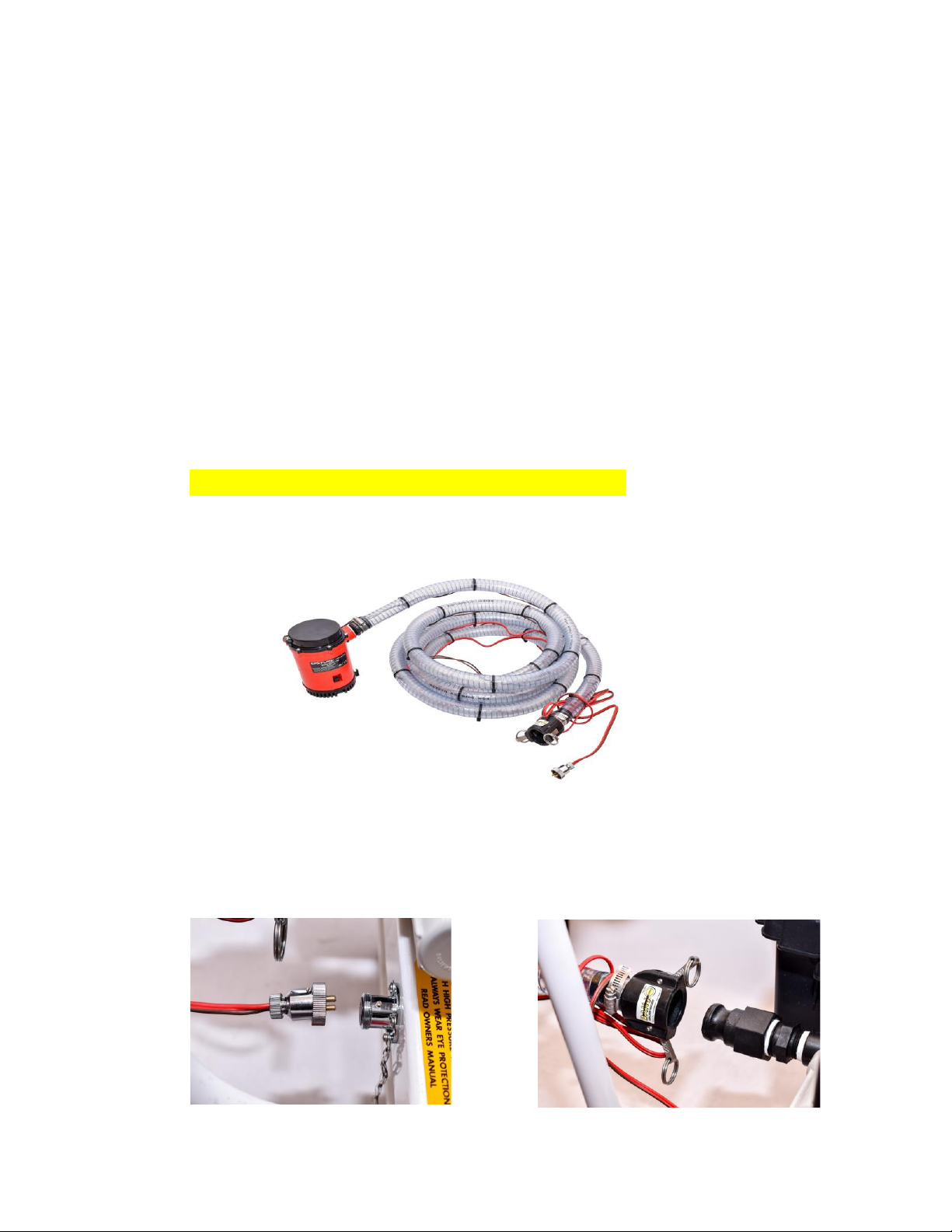
When feeding water to the CaviBlaster® power unit with the feed pump, connect
the 1″ diameter clear PVC feed hose to the cam-lock plug on the inline strainer
inlet.
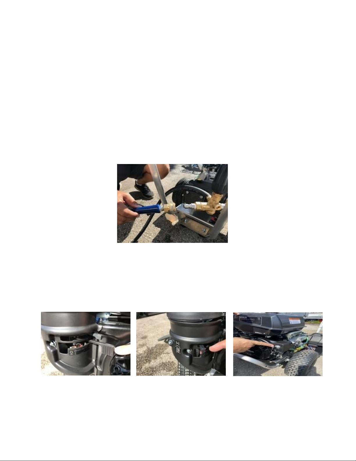
The feed hose has the feed pump on one end and a cam-lock socket on the other end. Insert the
electrical plug powering the feed pump into the waterproof electrical outlet on the end of the
power unit cart under the handle. Ensure that the knob on the plug is facing up and mates with
the notch in the outlet cover. If the plug is engaged upside down, the pump will turn in reverse.
Ensure that the feed hose is connected to the pressure pump, the feed pump is submerged in
water, and the wiring splice is kept dry prior to starting the feed pump. Either fresh water or
seawater can be used with this system.
Note: The feed pump has had a neoprene check valve installed in the discharge. This valve will prevent water from
draining out of the feed hose through the feed pump when the pump is turned off. However, this check valve
somewhat restricts the flow of water from the pump. If maximum water flow is required from the feed pump, the
check valve and stainless retaining washer can be removed from the pump discharge by removing the black hose
barb fitting. NEVER TURN OFF FEED PUMP WHILE WORKING.
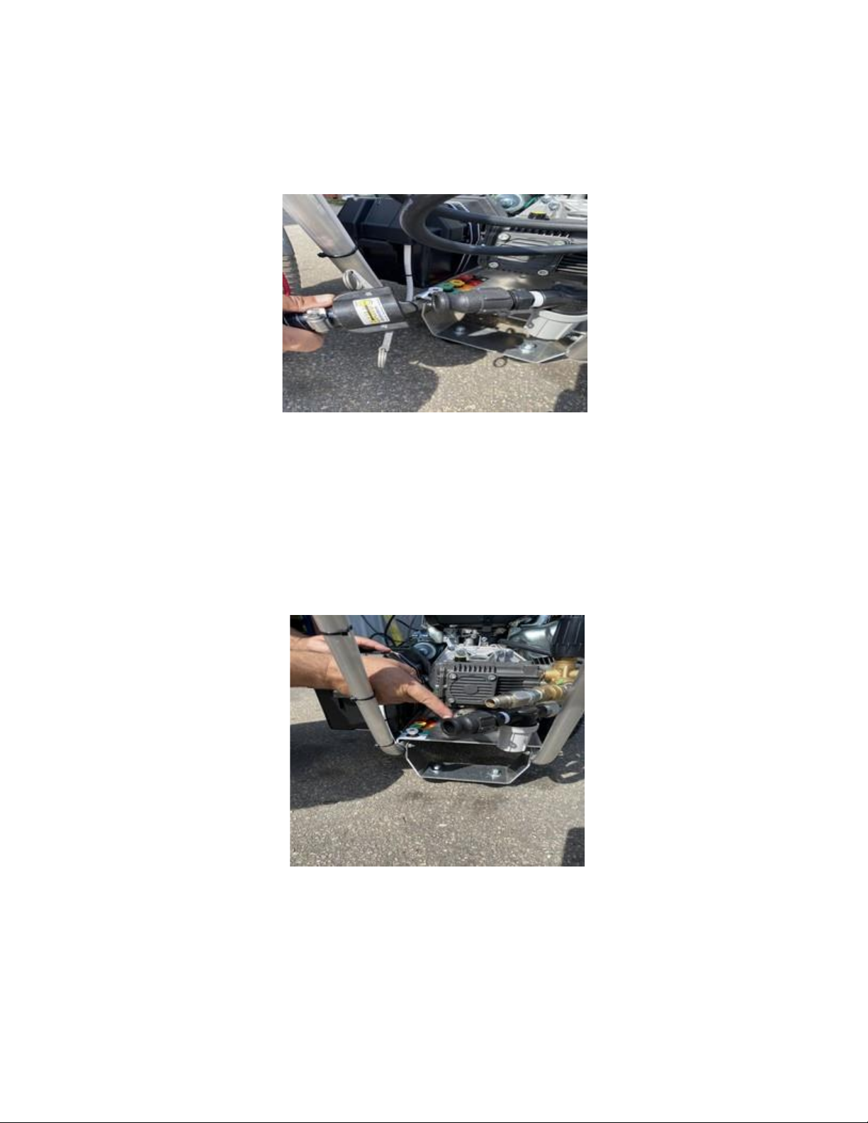
When feeding the CaviBlaster® with an alternate water source, the source must supply water at a
volume of greater than 6 gallons per minute at a maximum pressure of 70-psi. Connect the water
source to the inlet of the pressure pump (Figure 10). Ensure that the feed hose is connected to the
pressure pump and the water is on prior to starting the pressure pump.
Starting the CaviBlaster® power unit:
1. Start the feed pump and place in one feet of water, at the water source.
2. Ensure that the system is primed with water and that there are no leaks in the
system. The pressure pump is a positive displacement pump and water must be
supplied under pressure. Failure to pump feed water to the pressure pump will
result in damage to the pump.
3. Connect the 3/8″ high-pressure hose to the quick-connect plug under the
pressure-regulating unloader (Figure-11). The high-pressure hose has a brass quick-
connect socket on the end. The CaviBlaster® Model 0625-G can deliver the required
pressure utilizing up to 300 feet of 3/8″ diameter rubber hose.
Connect HP Hose to the quick connect under pressure regulator - Figure #11
4. Move throttle to the On position (figure 12) and fully engage choke (figure 13)
and then turn the key to start engine (figure 14).
Throttle at the On position - Figure #12 Fully engage Choke - Figure #13 Ignition key - Figure #14
5. Connect the gun to the high-pressure hose (Figure-15) and submerge the gun in
water.
Connecting the gun to the High Presure Hose - Figure #15
6. It is recommended that the gun trigger be in the open or “ON” position when
starting the engine. This will prevent a pressure shock wave from damaging the
pump in the instant that the engine is started.
7. Divers and nearby personnel must use appropriate hearing protection prior to
starting the engine.
8. Be sure the engine run switch is on (figure 12). Set the choke knob to close the
choke if the engine is cold or has not been running (figure 13). If the engine has
been running and is warm, leave the choke open. Adjust the throttle lever (Figure
12) one-third of the way from “MIN” toward “MAX” for correct engine start RPM.
Turn the ignition key, (figure 14) (several times as necessary) until the engine starts.
If the engine does not start, release the choke and try again.
9. Once the unit is running and warm, move the throttle to Max. (figure 16)
The system is now ready to operate. (figure 17)
Throttle to Max position - Figure #16 Overall system set up - Figure #17
Recommendations for Effective Results.
Once the engine is throttled up to operating speed and the water trigger is pulled,
the diver should find the most effective distance between the gun nozzle and the
surface being cleaned. When the diver is ready to commence cleaning operations,
ensure that the gun trigger is in the open or “ON” position, the gun is submerged
in the water and the water source is on, prior to throttling up the engine.
Ensure that the power unit operator and other people working in the vicinity of the
power unit wear appropriate hearing protection when the engine is running.
Gun efficient operating technique - Figure #18
1. The most efficient operating technique is to hold the nozzle 2-5 inches (5-12 cm)
away from the surface to be cleaned and at a 25° to 45° angle to the surface being
cleaned. The diver needs to observe the shape of the cavitating jet cone. At greater
depths, the higher ambient pressure will cause the jet cone to be shorter. The
widest zone of the cone is the most efficient part of the cavitating jet. Placing the
nozzle closer than 2 inches (5 cm) from the surface being cleaned will not allow for
efficient cavitation performance and will degrade the cleaning capability of the
CaviBlaster® system.
2. Follow all safety regulations that may be applicable to the work being performed.
3. If the diver operating the CaviBlaster® unit must be replaced or the cleaning
operation must be terminated, disengage the pressure pump by pulling down the
throttle lever in to the idle position and release the water pressure remaining in
the hose(s) by moving the gun trigger to the open or “ON” position while under
water. Revert to step 1 of the operating instructions when the diver or replacement
is ready to continue cleaning.
WARNING: Although the CaviBlaster® system is safe to use when
submerged in water, the system generates a high pressure (up to
2,500-psi) water stream, which can cause injury when the gun is out
of the water. ALWAYS keep the gun submerged when the pressure
pump is engaged.