CEBEK CD-34 User manual

CD-34CD-34
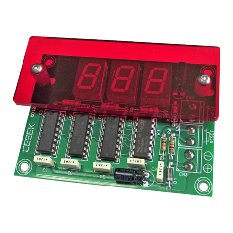
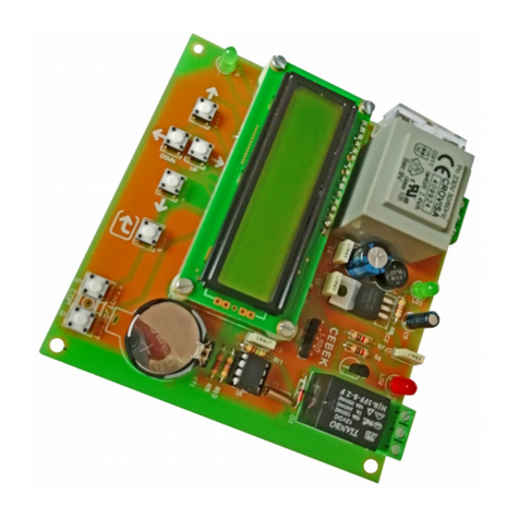
The CD-34 module is an automatism to monthly control and follow the operating and yield of the
apparatus, device. It has been specially designed to obtain a fast and accurate resume of the labour
calendar done by the controlled machine.
It indicates the hour to start the count, the starting date, the total worked hours, labour days, average per hour,
hours per day, operating time (per day, week, month).
Data are showed on a 13,5 mm display. It includes battery to maintain data when the module is not
connected (supplied), indicator leds, control buttons, front panel and terminals to make more easy the
connected
OPERATING.
2
COUNTERS CD-34CD-34
Ref. Full9813
HOURS CONTROLLER.
TECHNICAL CHARACTERISTICS.
Voltage. ..........................................................................................From 9 up to 12 V. DC.
Minimum Consumption. ................................................................70 mA.
Maximum Consumption. ...............................................................100 mA.
Battery. .......................................................................................... CR-20 (3 V.)
Protection Against Polarity Inversión. ............................................. Yes.
Hour Format. ................................................................................. 24 H.
Date Format. ................................................................................. Day, month and year.
Intermittent Time Hour / Date. ..................................................... 5 sec.
Display. .......................................................................................... 6 x 0,5“ Displays (13.5 mm.) and leds.
POWER SUPPLY. The CD-34 module had to be supplied
OPERATING. The CD-34, as module specially designed to control yield, could be used on restricted mode, to
avoid to modify data because of a wrong manipulation and/or an accident. For this reason, the keyboard usually
used to display data could be used to activate, stop or reset the module’s count only when you wish it. Then, the
employe even if he uses the keyboard for other applications, he could not have access to activation, Stop, Reset
Time adjustment functions.
PREPARATION OF THE MODULE. ACTIVATION, STOP, RESET AND HOUR ADJUSTMENTY. To have access to these
by a 9 - 12 V DC. power supply perfectly stabilised, for this
reason we recommended you the FE-71 power supply which has been developed to perfectly answer to the circuit
needs.
Connect the positive of the power supply to the positive terminal indicated in the wiring map, then connect also
the negative of the power supply to the negative terminal indicated in the circuit.
Verify that the assembly has been correctly done and activate the power supply.
functions, youhave to specially prepare the module. Connect both pins of the JP1 jumper, present on the PCB as
it is indicated on the schedule.
HOUR ADJUSTMENT. Verify that pins of the JP1 Jumper are connected. The first operation is to adjust the internal
hour of the CD-34 module. Before to supply the module, you have to maintain pressed the P3 button, placed on
the front part of the module, then maintaining pressed the button you have to supply the module. Automatically,
both displays (minutes and seconds) will be intermittent, hours displays are on fix position. Stop to press the P3
button.
Each time you wish to adjust hour, fix display correspond to data that you have to change meanwhile intermittent
displays correspond to stand by data. Firstly you could adjust hours displays. Press P1 or P2 buttons your data will
increase or dicrease. If you maintain pressed one of these button, during more than 1 sec. You could increase or
decrease data more quickly. Once time adjusted, press again P3 button. Now displays corresponding to minutes
are fixed and then you could adjust them. When this operation is done, you have to press again the P3 button.
With each pressure, the module will change to the next register (hours, minutes, days, months, etc.), allowing you
to adjut it thanks to P1 & P2 buttons during displays are stopped.
The last register, after years, required by the module is the present day. Then, numbers corresponding to each
day of the week from 1 up to 7 (being 1 Monday and 7 Sunday) will appear. Use P1 and P2 buttons to select the
correct day.
After configurate the day of the week, when you press the P3 button, the clock will be bloqued, confirming you
that adjustment operation is stopped. To leave this function, you have to desold the JP1 jumper and press P3
button.
ACTIVATION, STOP AND RESET. If the JP1 jumper were disconnected, connect it again. Then, P1, P2 and P3
buttons will be used to respectively control Activation, Stop and Reset functions. If you press the Start button, the
LD1 Led will light indicating that the timing of the circuit had been activated, registring from this instant first data.
The module will collect day after day, during the module’s supplying, the operating time of this one, storing data
on the memory when the module is not used.
Therefore, till you Stop or Reset the CD-34, the module will daily record operating times of the controlled
apparatus or devices during the month. At the end of the month, if you not activate the Reset function, the
module automatically reset the module and all data will start from zero. The Stop button is charged to stop the
module’s timing, and to leave it awaiting for a new information. All registers will be stored on the memory. LD1 led
will light off.
To reactivate timing, you have to press the Start button, the circuit will normally operate, registering data from the
point where it was previously stopped.
If youpress the Reset button, you stop the timing and erase all stored data till the date. Use this function with
careful, once this button pressed, data could be recuperated.
After the Reste, the mdoule will wait for a new information.
As soon as the Start, Stop or Reset function is done, youhave to desold the JP1 jumpler, to avoid to damage
stored datas.
PRESENTATION OF STORED DATA. To have access to stored data, you have to cancel Start, Stop and Reset
functions, desolding both pins of the JP1 Jumper. From this moment, Start, Stop and Reset buttons will be
1
JP1
Connect for following functions:
Activation.
Stop.
Reset.
Hour Adjustment.
Lateral View of the JP1 Jumper
3
CR202
3 V.
BATERY
Battery
JP1
JP1 Jumper on the PCB
Front part of the Module
StopStart
Hours/Days Minutes/Months Seconds/Years
LD1
LD2
Reset
P1 P2 P3
OPERATING.
ELECTRONIC CIRCUITS

CD-34CD-34
The CD-34 module is an automatism to monthly control and follow the operating and yield of the
apparatus, device. It has been specially designed to obtain a fast and accurate resume of the labour
calendar done by the controlled machine.
It indicates the hour to start the count, the starting date, the total worked hours, labour days, average per hour,
hours per day, operating time (per day, week, month).
Data are showed on a 13,5 mm display. It includes battery to maintain data when the module is not
connected (supplied), indicator leds, control buttons, front panel and terminals to make more easy the
connected
OPERATING.
2
COUNTERS CD-34CD-34
Ref. Full9813
HOURS CONTROLLER.
TECHNICAL CHARACTERISTICS.
Voltage. ..........................................................................................From 9 up to 12 V. DC.
Minimum Consumption. ................................................................70 mA.
Maximum Consumption. ...............................................................100 mA.
Battery. .......................................................................................... CR-20 (3 V.)
Protection Against Polarity Inversión. ............................................. Yes.
Hour Format. ................................................................................. 24 H.
Date Format. ................................................................................. Day, month and year.
Intermittent Time Hour / Date. ..................................................... 5 sec.
Display. .......................................................................................... 6 x 0,5“ Displays (13.5 mm.) and leds.
POWER SUPPLY. The CD-34 module had to be supplied
OPERATING. The CD-34, as module specially designed to control yield, could be used on restricted mode, to
avoid to modify data because of a wrong manipulation and/or an accident. For this reason, the keyboard usually
used to display data could be used to activate, stop or reset the module’s count only when you wish it. Then, the
employe even if he uses the keyboard for other applications, he could not have access to activation, Stop, Reset
Time adjustment functions.
PREPARATION OF THE MODULE. ACTIVATION, STOP, RESET AND HOUR ADJUSTMENTY. To have access to these
by a 9 - 12 V DC. power supply perfectly stabilised, for this
reason we recommended you the FE-71 power supply which has been developed to perfectly answer to the circuit
needs.
Connect the positive of the power supply to the positive terminal indicated in the wiring map, then connect also
the negative of the power supply to the negative terminal indicated in the circuit.
Verify that the assembly has been correctly done and activate the power supply.
functions, youhave to specially prepare the module. Connect both pins of the JP1 jumper, present on the PCB as
it is indicated on the schedule.
HOUR ADJUSTMENT. Verify that pins of the JP1 Jumper are connected. The first operation is to adjust the internal
hour of the CD-34 module. Before to supply the module, you have to maintain pressed the P3 button, placed on
the front part of the module, then maintaining pressed the button you have to supply the module. Automatically,
both displays (minutes and seconds) will be intermittent, hours displays are on fix position. Stop to press the P3
button.
Each time you wish to adjust hour, fix display correspond to data that you have to change meanwhile intermittent
displays correspond to stand by data. Firstly you could adjust hours displays. Press P1 or P2 buttons your data will
increase or dicrease. If you maintain pressed one of these button, during more than 1 sec. You could increase or
decrease data more quickly. Once time adjusted, press again P3 button. Now displays corresponding to minutes
are fixed and then you could adjust them. When this operation is done, you have to press again the P3 button.
With each pressure, the module will change to the next register (hours, minutes, days, months, etc.), allowing you
to adjut it thanks to P1 & P2 buttons during displays are stopped.
The last register, after years, required by the module is the present day. Then, numbers corresponding to each
day of the week from 1 up to 7 (being 1 Monday and 7 Sunday) will appear. Use P1 and P2 buttons to select the
correct day.
After configurate the day of the week, when you press the P3 button, the clock will be bloqued, confirming you
that adjustment operation is stopped. To leave this function, you have to desold the JP1 jumper and press P3
button.
ACTIVATION, STOP AND RESET. If the JP1 jumper were disconnected, connect it again. Then, P1, P2 and P3
buttons will be used to respectively control Activation, Stop and Reset functions. If you press the Start button, the
LD1 Led will light indicating that the timing of the circuit had been activated, registring from this instant first data.
The module will collect day after day, during the module’s supplying, the operating time of this one, storing data
on the memory when the module is not used.
Therefore, till you Stop or Reset the CD-34, the module will daily record operating times of the controlled
apparatus or devices during the month. At the end of the month, if you not activate the Reset function, the
module automatically reset the module and all data will start from zero. The Stop button is charged to stop the
module’s timing, and to leave it awaiting for a new information. All registers will be stored on the memory. LD1 led
will light off.
To reactivate timing, you have to press the Start button, the circuit will normally operate, registering data from the
point where it was previously stopped.
If youpress the Reset button, you stop the timing and erase all stored data till the date. Use this function with
careful, once this button pressed, data could be recuperated.
After the Reste, the mdoule will wait for a new information.
As soon as the Start, Stop or Reset function is done, youhave to desold the JP1 jumpler, to avoid to damage
stored datas.
PRESENTATION OF STORED DATA. To have access to stored data, you have to cancel Start, Stop and Reset
functions, desolding both pins of the JP1 Jumper. From this moment, Start, Stop and Reset buttons will be
1
JP1
Connect for following functions:
Activation.
Stop.
Reset.
Hour Adjustment.
Lateral View of the JP1 Jumper
R203
C2
3 V.
BATEY
R
Battery
JP1
JP1 Jumper on the PCB
Front part of the Module
StopStart
Hours/Days Minutes/Months Seconds/Years
LD1
LD2
Reset
P1 P2 P3
OPERATING.
ELECTRONIC CIRCUITS

4
HOW TO REMOVE THE BATTERY.
REMOVE AND SUGGESTIONS REGARDING BATTERY. When the mdoule is not supplied, the module maintains
timing thanks to the battery. The hour display is cancelled till the module is again normally supplied; then the
hour and the rest of the others functions will be activated again.
With the time and according to the number and duration of situations in which
the module was not supplied, the battery will be discharged. In this case, the
module could not recuperate the hour and you have to remove the battery.
The required battery is a 3 V CR-2032 battery, and you could purchase it to your
distributor.
When you will substituate it, be careful in respecting the corresponding polarity.
See the schedule. Do not remove the battery if the module’s power supply is
connected, neither hardly handle it.
C20
R32
3V
.
BTRYAE
Battery
All the module’s CEBEK have 3 years of total warranty in thecnical
repairing, and spares from the date of buy.
CEBEK is trade make of FADISEL S.L. more than 300 module’s are avaible in
stock for any purpose request our CATALOGUE, or visit our Web.
Http://www.cebek.com
TECHNICAL CONSULTATIONS.
If you have any doubt, you could contact your wholesaler or our Technical Department.
- Via E-Mail, sat@cebek.com | by mail P.O Box 23455 - 08080 BARCELONA - SPAIN.
- Keep the invoice of this module. For any repair, the corresponding invoice had to be added. If the invoice is
not presented together with this module, the module’s warranty will be automatically cancelled.
GENERAL WIRING MAP.
3CR20 2
3 V.
BATERY
Battery
JP1
Module
CD-34
Power Supply
230 V. AC. Mains
Mains
Switch
250 mA.
Fuse
Apparatus o Machine
to be controlled
by the CD-34
Led
Module
FE-71
TRANSFORMER.
FE-71
0
0
12 230
COUNTERS CD-34CD-34
Ref. Full9813
CD-34CD-34
OPERATING.
HOURS CONTROLLER.
3
JP1
Desold to show
stored registers.
Lateral View of the JP1 Jumper
converted on P1, P2 and P3 buttons.
It is very important to take in account two basic aspects : Firstly module will record data from the present month,
erasing them each new month. For this reason, if you have to note monthly data, you have to write them at the
latest time the last day of the month. The second aspect is the accurate displayed data. Thanks to the calcul of
time averages, etc... The module could display as amaximum an error of minutes. Each button is used to have
access to different registers and thanks to the LD2 led, you could know which is the register :
P3. Press the P3 button till the LD2 led will light on. On the display you could read the total number of the real
hours that the mdoule had operated, independently if the module had been connected some instants each
day or the quantity of days, this register add and show total hours and minutes concerning the connection
apparatus from the beginning till the date. If you press again on the P3 button, the LD2 led will light on an
intermitten mode, indicating thatthe displayed register correspond to the starting date (the last time that the Start
button had been activated). If you press again, the display will show the third and last register for the P3 button.
The LD2 led will light off and display show the register corresponding to the starting hour (the last time that the Start
button had been activated). If youpress again on the P3 button, the module will display these three register on a
cyclic mode.
P2. The P2 button show 2 registers. If youpress a first time, the LD2 led will light on, indicating that the displayed
register correspond to the total number of operating days for the controlled apparatus or device. Then, the
module will add all days of the month, in which the apparatus had been connected, independently if the
apparatus had been connected several hours or one minute during the day. If the apparatus has not been
connected one day, this day is not taking in account.
If you press again on the P2 button, the module willshow the last register. The LD2 led will intermittently light and
the display will show the average of worked hours per day. If you press again several times on the P2 button, the
module will display these two registers according to a cyclic mode.
HOW TO HAVE A FAST ACCESS TO CD-34’S REGISTERS.
Frontal del Módulo
Hours/Days Minutes/Months Seconds/Years
LD1
LD2
P1
P1
P2
P3
P2 P3
1st pulsation. LD2 light on. Time for “today” corresponding to the apparatus’operating time.
2sd pulsation. LD2 intermittent. Time for “this week” corresponding to the apparatus’operating
1st pulsation. LD2 light on. Number of days corresponding to the appartus’ connection.
2sd pulsation. LD2 intermittent. Hours average done per day.
1st pulsation. LD2 light on. Number of Total operating Hours.
2sd pulsation. LD2 intermittent. Starting Date.
HOW TO CONNECT THE MODULE AND THE APPARATUS TO CONTROL. To allow the CD-34 to control a
determinated apparatus, you have to install it in parallel. Then, supplying or not the apparatus , you could also
supply or not the CD-34. See the schedule.
Y
S
E
R
A
ELECTRONIC CIRCUITS
4
HOW TO REMOVE THE BATTERY.
REMOVE AND SUGGESTIONS REGARDING BATTERY. When the mdoule is not supplied, the module maintains
timing thanks to the battery. The hour display is cancelled till the module is again normally supplied; then the
hour and the rest of the others functions will be activated again.
With the time and according to the number and duration of situations in which
the module was not supplied, the battery will be discharged. In this case, the
module could not recuperate the hour and you have to remove the battery.
The required battery is a 3 V CR-2032 battery, and you could purchase it to your
distributor.
When you will substituate it, be careful in respecting the corresponding polarity.
See the schedule. Do not remove the battery if the module’s power supply is
connected, neither hardly handle it.
C203
R2
3 V.
BATERY
Battery
All the module’s CEBEK have 3 years of total warranty in thecnical
repairing, and spares from the date of buy.
CEBEK is trade make of FADISEL S.L. more than 300 module’s are avaible in
stock for any purpose request our CATALOGUE, or visit our Web.
Http://www.cebek.com
TECHNICAL CONSULTATIONS.
If you have any doubt, you could contact your wholesaler or our Technical Department.
- Via E-Mail, sat@cebek.com | by mail P.O Box 23455 - 08080 BARCELONA - SPAIN.
- Keep the invoice of this module. For any repair, the corresponding invoice had to be added. If the invoice is
not presented together with this module, the module’s warranty will be automatically cancelled.
GENERAL WIRING MAP.
3R20 2C
3 V.
BATERY
Battery
JP1
Module
CD-34
Power Supply
230 V. AC. Mains
Mains
Switch
250 mA.
Fuse
Apparatus o Machine
to be controlled
by the CD-34
Led
Module
FE-71
TRANSFORMER.
FE-71
0
0
12 230
COUNTERS CD-34CD-34
Ref. Full9813
CD-34CD-34
OPERATING.
HOURS CONTROLLER.
3
JP1
Desold to show
stored registers.
Lateral View of the JP1 Jumper
converted on P1, P2 and P3 buttons.
It is very important to take in account two basic aspects : Firstly module will record data from the present month,
erasing them each new month. For this reason, if you have to note monthly data, you have to write them at the
latest time the last day of the month. The second aspect is the accurate displayed data. Thanks to the calcul of
time averages, etc... The module could display as amaximum an error of minutes. Each button is used to have
access to different registers and thanks to the LD2 led, you could know which is the register :
P3. Press the P3 button till the LD2 led will light on. On the display you could read the total number of the real
hours that the mdoule had operated, independently if the module had been connected some instants each
day or the quantity of days, this register add and show total hours and minutes concerning the connection
apparatus from the beginning till the date. If you press again on the P3 button, the LD2 led will light on an
intermitten mode, indicating thatthe displayed register correspond to the starting date (the last time that the Start
button had been activated). If you press again, the display will show the third and last register for the P3 button.
The LD2 led will light off and display show the register corresponding to the starting hour (the last time that the Start
button had been activated). If youpress again on the P3 button, the module will display these three register on a
cyclic mode.
P2. The P2 button show 2 registers. If youpress a first time, the LD2 led will light on, indicating that the displayed
register correspond to the total number of operating days for the controlled apparatus or device. Then, the
module will add all days of the month, in which the apparatus had been connected, independently if the
apparatus had been connected several hours or one minute during the day. If the apparatus has not been
connected one day, this day is not taking in account.
If you press again on the P2 button, the module willshow the last register. The LD2 led will intermittently light and
the display will show the average of worked hours per day. If you press again several times on the P2 button, the
module will display these two registers according to a cyclic mode.
HOW TO HAVE A FAST ACCESS TO CD-34’S REGISTERS.
Frontal del Módulo
Hours/Days Minutes/Months Seconds/Years
LD1
LD2
P1
P1
P2
P3
P2 P3
1st pulsation. LD2 light on. Time for “today” corresponding to the apparatus’operating time.
2sd pulsation. LD2 intermittent. Time for “this week” corresponding to the apparatus’operating
1st pulsation. LD2 light on. Number of days corresponding to the appartus’ connection.
2sd pulsation. LD2 intermittent. Hours average done per day.
1st pulsation. LD2 light on. Number of Total operating Hours.
2sd pulsation. LD2 intermittent. Starting Date.
HOW TO CONNECT THE MODULE AND THE APPARATUS TO CONTROL. To allow the CD-34 to control a
determinated apparatus, you have to install it in parallel. Then, supplying or not the apparatus , you could also
supply or not the CD-34. See the schedule.
Y
S
E
R
A
ELECTRONIC CIRCUITS
Table of contents
Other CEBEK Control Unit manuals
Popular Control Unit manuals by other brands

Texas Instruments
Texas Instruments TSC4270 user guide

Carrier
Carrier INFINITY SYSTXCCITC01 owner's manual

Master
Master X60 EGO user manual

Bray
Bray 752 Series Installation, operation and maintenance manual

Elation
Elation MIDICON PRO user manual

Leviton
Leviton 10A11-1 Installation instructions and user guide