I-217
ABOUT THE OUTPUT: During operation of the circuit, an accor ing to its loa , a fluctuation or an output malfunction may occur. If this happens, install
an anti-spark circuit between the two contacts of the relay use in connection
SUR LA SORTIE: Pen ant le fonctionnement u circuit, et selon sa charge, une fluctuation ou un ysfonctionnement e sortie peuvent se pro uire. Si
cela se pro uit, l'installation 'un circuit anti-étincelle entre les eux contacts u relais utilisés ans le ca re.
CONSIDERACIONES SOBRE LA SALIDA : Durante el funcionamiento el circuito, y según sea su carga, po rá pro ucirse una fluctuación o un
incorrecto funcionamiento e la sali a. Si esto ocurre, instale un circuito anti-chispas entre los os contactos el relé utiliza os en la conexión .
ACTIVATION: The circuit supports activation button or by power supply. If you close or join the JP1 jumper every time you supply to the circuit, the
timer will start automatically.
If left open, the circuit is activate only when you press the start button.
To activate the switch circuit, install a button on the terminal "Start". Ensure that the cable length oes not excee 30 cm. If excee e , use shiel e
cable to connect the brai to the negative input terminal of the switch.
Remember to leave the open jumper JP1.
ACTIVATION: Le circuit pren en charge le bouton 'activation ou par alimentation. Si vous fermez ou join re le cavalier JP1 chaque fois que vous
fournissez sur le circuit, la minuterie émarre automatiquement.
S'il reste ouvert, le circuit est activé uniquement lorsque vous appuyez sur le bouton e émarrage.
Pour activer le circuit e commutation, installer un bouton sur le terminal "Démarrer". Assurez-vous que la longueur u câble ne épasse pas 30 cm.
En cas e épassement, utiliser un câble blin é pour raccor er la tresse à la borne 'entrée négative e l'interrupteur.
N'oubliez pas e laisser le cavalier JP1 ouvert.
ACTIVACION : El circuito a mite la activación por pulsa or o por suministro e tensión. Si cierra o une el jumper JP1, ca a vez que proporcione
tensión al circuito, automáticamente se iniciará la temporización.
Si lo eja abierto, el circuito solamente se activará cuan o presione el pulsa or e inicio.
Para activar el circuito por pulsa or, instale un pulsa or en el borne “Start”. Procure que la longitu el cable no supere los 30 cm. Si lo supera, utilice
cable apantalla o, conectan o la malla e éste al terminal negativo e la entra a e pulsa or.
Recuer e que eberá ejar el jumper JP1 abierto.
TIMING: Setting timers is one by the two micro-switches batteries incorporating the circuit. The battery monitor DIP1 time of the relay, (work time)
an the DIP2 the relay off time (soak time).
Each battery has 6 "Switchs" which accor ing to their status, On or Off, configure in one way or another time.
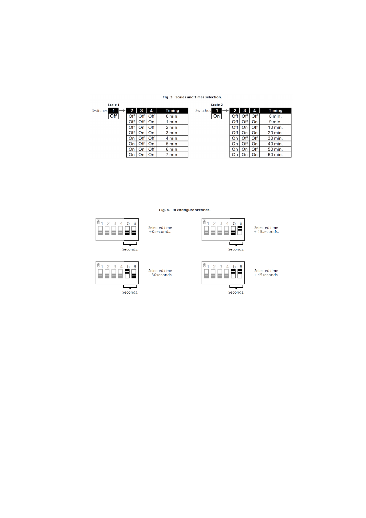
The batteries are ivi e into: the time scale, forme by the switch 1, the selection of the secon , compose of the switches 2, 3, an 4, an the
selection of tenths, forme by the switches 5 an 6
TIMEOUT : Réglage es minuteries se fait par les eux micro-interrupteurs batteries intégrant le circuit. Le temps e moniteur e batterie DIP1 u
relais, (temps e travail) et le DIP2 le relais e temps (temps 'immersion).
Chaque batterie ispose e 6 "Switchs" qui, selon leur état>>, ON ou OFF, configurés 'une manière ou 'une autre époque.
Les batteries sont ivisés en: l'échelle e temps, formé par l'interrupteur 1, la sélection u secon , composé es interrupteurs 2, 3, et 4, et la sélection
es ixièmes, formé par les commutateurs 5 et 6.
TEMPORIZACION : El ajuste e las temporizaciones se realiza me iante las os baterías e micro-interruptores que incorpora el circuito. La batería
DIP1 controlará el tiempo e conexión el relé, (tiempo e trabajo) y la batería DIP2 el tiempo e esconexión el relé, (tiempo e reposo).
Ca a batería ispone e 6 “Switchs” que según su situación, On u Off, configurarán e un mo o u otro los tiempos.
Las baterías que an ivi i as en: la escala e tiempos, forma a por el switch 1, la selección e los segun os, compuesta por los switchs 2, 3, y 4; y
la selección e écimas, forma a por los switchs 5 y 6.
The time scale on the map allows selection of the latter, two ifferent scales. As you position the switch 1 to On or Off, the same combination of switches
2, 3 an 4 will choose two ifferent times.
Set DIP 1 thus to allocate time to work an assign DIP2 stan ing time.
First, using the select switch 1 the time scale that best suits the timing to perform.
Then, using the switches 2, 3 an 4, choose the secon or the appropriate binary combination to assign to the timing, making the appropriate binary
combination.
2