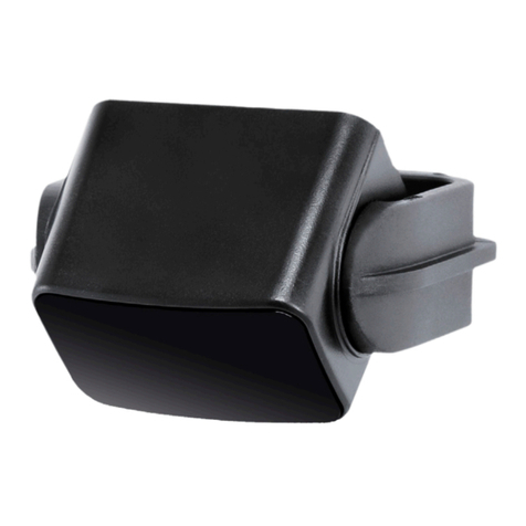
Cedes TOF/TaxI User manual

English Pages 2 - 17
Deutsch Seiten 19 - 36
CEDES AG is certied according to ISO 9001: 2008
CEDES AG ist zertiziert nach ISO 9001: 2008
Installation and Operation Manual
Montage- und Betriebsanleitung
109 949 | 120822 | V 1.3
TOF/Taxi
EN 13849-1
RoHS
D0AS0001

TOF/Taxi
2© CEDES |V 1.3
1. About this manual
This “TOF/Taxi Installation and Operation Manual”,
with metric and US measurements is the original
version.
The version number is printed at the bottom of each
page.
To make sure you have the latest version, visit
www.cedes.com where this manual and related
documents can be downloaded.
1.1 Measurements
Measurements are, if not stated otherwise, given in
mm (non-bracketed numbers) and inches (numbers
in brackets).
1.2 Related documents
TOF/Taxi datasheet en
including ordering information
Part No. 001 179 en
1.3 CEDES headquarters
CEDES AG
Science Park
CH-7302 Landquart
Switzerland
Contents
1. About this manual 2
1.1 Measurements 2
1.2 Related documents 2
1.3 CEDES headquarters 2
2. Safety information 3
2.1 Non-intended use 3
3. Symbols, safety messages 3
3.1 Safety message categories 3
4. Introduction 4
4.1 Features of the TOF/Taxi 4
4.2 Type description 4
5. Overview 5
5.1 Delivery package 5
5.2 TOF/Taxi product overview 6
5.3 Alignment 6
6. Conguration 7
6.1 DIP switch 1 – Mounting position 7
6.2 DIP switch 2 – Number of active rows 7
6.3 DIP switch 3 – Wall blanking 8
6.4 DIP switch 4 – Door handle blanking 8
6.5 Pot 1 and Pot 2 – Detection area 8
7. Installation 10
8. Electrical connection 11
8.1 Output 11
8.2 Test input 11
9. Start-up 12
9.1 Test run 12
10. LEDfunctions 12
11. Synchronization 12
11.1 Synchronization diagram 13
12. Timing diagram 14
13. Troubleshooting 14
14. Maintenance 15
15. Uninstalling TOF/Taxi 15
16. Disposal 15
17. Technicaldata 16
18. Dimensions 17
19. Certicate/Zertikat 36
CEDES AG reserves the right to modify or change technical data without prior notice.

© CEDES |V 1.3 3
TOF/Taxi English
2. Safety information
IMPORTANT!
READBEFOREINSTALLATION!
The TOF/Taxi was developed and manufactured
using state-of-the-art systems and technologies.
However, injury and damage to the sensor can still
occur.
To ensure safe conditions:
Read all enclosed instructions and information.
Follow the instructions given in this manual
carefully.
Observe all warnings included in the
documentation and attached to the sensor.
Do not use the sensor if it is damaged in any way.
Keep the instruction manual on site.
The TOF/Taxi should only be installed by authorized
and fully trained personnel! The installer or system
integrator is fully responsible for the safe integration
of the sensor. It is the sole responsibility of the
planner and/or installer and/or buyer to ensure
that this product is used according to all applicable
standards, laws and regulations in order to ensure
safe operation of the whole application.
Any alterations to the device by the buyer, installer
or user may result in unsafe operating conditions.
CEDES is not responsible for any liability or warranty
claim that results from such manipulation.
Failure to follow instructions given in this manual
and/or other documents related to the TOF/Taxi
may cause customer complaints, serious call backs,
damage, injury or death.
2.1 Non-intended use
The TOF/Taxi must not be used for:
• Equipment in explosive atmospheres
• Equipment in radioactive environments
Use only specic and approved safety devices for
such applications, otherwise serious injury or death
or damage to property may occur!
3. Symbols, safety messages
Symbol Meaning
Single instruction or measures in
no particular order
1.
2.
3.
Sequenced instructions
List, in no order of importance
Reference to a chapter, illustration
or table within this document
Important: Important information for the
correct use of the sensor
3.1 Safety message categories
Warningofserioushealthrisks
WARNING
Serioushealthrisks
Highlights critical information for the safe use
of the sensor. Disregarding these warnings
can result in serious injury or death.
Follow the measures highlighted by the
triangle-shaped arrows
Consult the safety information in Chapter
2 of this manual
Cautionofpossiblehealthrisks
CAUTION
Possiblehealthrisks
Highlights critical information for the safe use
of the sensor. Disregarding these warnings
can result in injury.
Follow the measures highlighted by the
triangle-shaped arrows
Consult the safety information in Chapter
2 of this manual
Noticeofdamagerisk
NOTICE
Riskofdamage
Disregarding these notices can lead to
damage to the sensor, the door controller
and/or other devices.
Follow the measures highlighted by the
triangle-shaped arrows

TOF/Taxi
4© CEDES |V 1.3
4. Introduction
The TOF/Taxi is designed as a infrared sensor used
in swing door applications. Both the leading and
hinge edges of a swing door pose a risk of injury.
This is particularly true when a swing door opens
in the direction of approaching pedestrian traffic –
potentially leading to a collision between door and
a person.
The TOF/Taxi is designed to safeguard the door area
during the entire opening and closing cycle.
This means when the door opens toward a wall, the
TOF/Taxi can distinguish between the wall and a
person or object entering its detection area (i.e. the
wall can be ignored by the sensor). Door handles can
also be ignored by the sensor.
Figure 1: A typical TOF/Taxi application
4.1 Features of the TOF/Taxi
• Time-of-Flight principle (TOF)
• Provides maximum safeguarding performance by
recognizing and ignoring door handles and walls
• Detects objects up to 75 cm (30 in) from the door
edge (at a detection height of 3 m / 10 ft) to ensure
the door can easily stop in time
• Safety Category 2, Performance Level C
• A single sensor safeguards doors up to a width of
2.1 m (6.9 ft) and a height of 3 m (10 ft)
4.2 Type description
Figure 2: TOF/Taxi type description
Test input logic
TAH Test active high
TAL Test active low
TOF / Taxi – x – xxx – xx – xxx
Output logic
LO Light on
DO Dark on
Output type
PNP
NPN
Output version
N Semiconductor output
CCAN bus

© CEDES |V 1.3 5
TOF/Taxi English
5. Overview
The TOF/Taxi is a camera sensor based on Time-of-Flight technology and consists of an active infrared emitter
and a receiver combined in the same housing. The measurement of the time and amount of reflected light
gives an exact picture of the detection area.
When someone or something enters the safeguarded area, the amount of light and reflection time changes.
As long as the person or object stays in the detection area, the output sends a signal to the connected door
controller. As soon as the detection area is clear, the output switches to indicate that the area is “clear”.
For details Chapter 12. If several TOF/Taxis are mounted on the hinge edges of a double swing door,
synchronization is necessary Chapter 11.
.
CAUTION
Damage to the eye
Although the TOF/Taxi does not emit
dangerous amounts of infrared light, long
exposure to intense infrared light sources
can result in damage to the eyes.
To avoid any risks:
Never look directly into the active infrared
emitter from a close distance.
Always mount the TOF/Taxi with the
optical window facing downward.
5.1 Deliverypackage
Each delivery package contains:
• 1 × TOF/Taxi sensor
• 1 × mounting plate
• 1 × mounting bracket
• 2 × mounting screws
• 1 × connection cable, 3 m (10 ft)
• 1 × Installation and Operation Manual
• 1 × drilling template
Figure 3: TOF/Taxi mounted on the leading edge of a single
leafed swing door
Figure 4: TOF/Taxi mounted on the hinge edge of a single
leafed swing door
Figure 5: TOF/Taxi mounted on a double leafed swing door
Figure 6: TOF/Taxi components

TOF/Taxi
6© CEDES |V 1.3
5.2 TOF/Taxi product overview
TOF/Taxi main parts:
1Positioning pins
2 Center axis
3 Connection cable socket
4 Mounting bracket
5 Cooling fins
6 Potentiometers
7 DIP switches
8 Status LED
9 Optical window
5.3 Alignment
The alignment of the sensor is dependent on application, installation and settings. The TOF/Taxi can be
mounted on both the leading edge ( Figure 3) and the hinge edge ( Figure 4) of a door. Dimensions vary
according to mounting height.
Allmeasurementsinmm(normalnumbers)andinches(inbrackets)
RIGHT LEFT
l = 1000 ... 3000 (39.4 ... 118)
43°
43°
l = 2100 (82.7)
200 (7.9)
146 (5.7)
239 (9.4)
549 (21.6)
Row 1
Row 2
Row 3
w = 300 ... 2100
(11.8 ... 82.7)
w = 300 ... 2100
(11.8 ... 82.7)
Figure 8: Detection area dimensions in both front and side views.
9
5
6
8
3
2
7
4
1
Figure7: TOF/Taxi overview

© CEDES |V 1.3 7
TOF/Taxi English
6. Configuration
There are four DIP switches and two potentiometers
to adjust the TOF/Taxi according to the application.
Use a small screw driver and carefully adjust the
settings.
NOTICE
Mechanical damage to the TOF/Taxi
Do not turn the potentiometers beyond
their mechanical limits.
6.1 DIP switch 1 – Mounting position
The TOF/Taxi can be mounted on the right or left
side of a door, facing downward. The left or right
mounting position is set using DIP switch 1.
Important: Whether the mounting position is above
the leading or the hinge edge of the door is irrelevant
to the setting of DIP switch 1.
Table 1: DIP switch 1 settings
DIP switch 1 position Mounting position
ON Mounting on the right
OFF Mounting on the left
6.2 DIP switch 2 – Number of active rows
The detection area of the TOF/Taxi consists of
three rows of IR beams ( Figure 8 for details).
DIP switch 2 activates either only the row nearest to
the door (Row 1) or all 3 rows.
Table 2: DIP switch 2 settings
DIP switch 2 position Number of active rows
ON All 3 rows
OFF Row 1 only
1 2 3 4
1
0
2
3
4
1
0
2
3
4
DIP switch
Pot 1 Pot 2
OFF
ON
Figure 9: DIP switches and potentiometers on TOF/Taxi
Figure10:Mounting position on the left and right side of a
swing door
Figure 11: TOF/Taxi with one active row (left) and three active
rows (right). Single rows are shown for clarity.

TOF/Taxi
8© CEDES |V 1.3
6.3 DIPswitch3–Wallblanking
When the TOF/Taxi-equipped swing door opens
towards a wall, the TOF/Taxi can be set to recognize
the wall and blank (ignore) it while maintaining full
safeguarding capability in the remaining parts of the
detection area.
Important: Wall blanking must only be set after the
detection area width and length are set and checked.
Important: A wall is defined as a solid, flat, vertical
plane which is at least as high and as wide as the
door itself.
Important: Wall blanking will only work if all three
rows are activated Chapter 6.2.
Important: If the TOF/Taxi is mounted on the hinge
edges the space between the door and the wall must
be larger than 0.15 m (5.9 in).
Table 3: DIP switch 3 settings
DIP switch 3 position Wallblanking
ON Enabled
OFF Disabled
6.4 DIPswitch4–Doorhandleblanking
To prevent the door handle from triggering the
TOF/Taxi, the area containing the door handle can be
blanked by setting DIP switch 4 to ON. This reduces
the detection area length of Row 1 by approximately
1 m (40 in), putting it well above the standard height
for door handles.
Important: Door handle blanking will only work if all
three rows are activated Chapter 6.2.
Table 4: DIP switch 4 settings
DIP switch 4 position Doorhandleblanking
ON Enabled
OFF Disabled
6.5 Pot 1 and Pot 2 – Detection area
There are two potentiometers for the adjustment of
the detection area referred to as Pot 1 and Pot 2.
Pot 1 is used to adjust the detection area length
( Figure 14). Pot 2 is then used to adjust the
detection area width in relation to the detection area
length.
Figure 12: As the swing door is approaching the wall,
TOF/Taxi reduces its detection area constantly
Figure 13: Door handle blanking reduces the innermost row
in length (single rows are shown for clarity)
ca. 1 m /40 in
Figure 14: Using Pot 1 and Pot 2 to adjust the detection area
Pot 1: detection area length (l)
Pot 2: detection
area width (w)

© CEDES |V 1.3 9
TOF/Taxi English
Pot 1: Detection area length
Pot 1 is located directly to the right of
the DIP switches. It sets the detection
area length (l) between 1 m (40 in)
and 3 m (120 in).
Important: The detection area length
must be set about 0.2 m (8 in) above
floor level as the floor would otherwise
interfere with the sensor’s detection
ability.
Adjust Pot 1 according to
Table 5 / Table 6.
Pot 2: Detection area width
Pot 2 sets the detection area width (w)
in relation to the detection area length.
The width can be adjusted between 0.3
and 0.7 × the detection area length.
Adjust Pot 2 according to Table 7 /
Table 8.
Example (row/column highlighted
in gray): For a door 2.7 m (108 in) high
and 1.5 m (59 in) wide, the detection
area length (l) has already been set
to 2.5 m (100 in). The detection area
width (w) should now be set to 1.5 m
(59 in). In order to do this, take the
following steps:
1. Look up the corresponding
detection area length row in
Table 7 / Table 8
(i.e. 2.5 m / 100 in).
2. Move along this row to the desired
detection area width (i.e. 1.5 m /
59 in).
3. Directly below this figure you will
find the required Pot 2 setting, in
this example the value is 3.
4. Set Pot 2 using a small
screwdriver
Detection area width w [in]
Detection area length l [in]
40 12 14 16 18 20 22 24 26 28
50 15 17 20 22 25 27 30 32 35
60 18 21 24 27 30 33 35 39 41
70 21 24 28 31 35 38 41 45 48
80 24 27 32 35 39 43 47 51 55
90 27 31 35 40 45 49 53 58 62
100 30 35 39 45 49 54 59 64 69
110 33 38 43 49 54 59 65 71 76
120 35 41 47 53 59 65 71 77 83
0 0.5 1 1.5 2 2.5 3 3.5 4
Pot 2 setting
Table 8: Pot 2 / Detection area width in inches
Table 5: Pot 1 / Detection area length in m
Detection area
length l [m] 1 1.25 1.5 1.75 2 2.25 2.5 2.75 3
Pot 1 setting 0 0.5 11.5 22.5 33.5 4
Table 6: Pot 1 / Detection area length in inches
Detection area
length l [in] 40 50 60 70 80 90 100 110 120
Pot 1 setting 0 0.5 11.5 22.5 33.5 4
Detection area width w [m]
Detection area length l [m]
1.0 0.3 0.35 0.4 0.45 0.5 0.55 0.6 0.65 0.7
1.25 0.38 0.44 0.5 0.56 0.63 0.69 0.75 0.81 0.88
1.50 0.45 0.53 0.60 0.68 0.75 0.83 0.9 0.98 1.05
1.75 0.53 0.61 0.7 0.79 0.88 0.96 1.05 1.14 1.23
20.6 0.7 0.8 0.9 11.1 1.2 1.3 1.4
2.25 0.68 0.79 0.9 1.01 1.13 1.24 1.35 1.46 1.58
2.5 0.75 0.88 11.13 1.25 1.38 1.5 1.63 1.75
2.75 0.83 0.96 1.1 1.24 1.38 1.51 1.65 1.79 1.93
3.0 0.9 1.05 1.2 1.35 1.5 1.65 1.8 1.95 2.1
0 0.5 1 1.5 2 2.5 3 3.5 4
Pot 2 setting
Table7:Pot 2 / Detection area width in m

TOF/Taxi
10 © CEDES |V 1.3
WARNING
Electrical and mechanical hazards
Electrical shock and unexpected door
movement can cause serious injury or
death.
Do not configure the sensor on the
working door
Follow all applicable safety measures
Use only specic and approved tools
If TOF/Taxi must be readjusted, the
main power supply must be switched
off and marked as out of service.
1. Switch off main power to the door and the door
control unit for your own safety and mark clearly
that the door is out of service.
2. Drill the mounting holes for the mounting plate in
the corner of the door leaf, using the enclosed
drilling template.
Important: The mounting plate must be
mounted horizontally on the door. The
TOF/Taxi sensor can then be snapped-on tilted to
the right or the left, according to the holes in the
mounting plate.
Important: If the cable can be routed through the
door itself, an additional hole must be drilled for
the cable routing. Otherwise the cable must be
guided along the surface of the door.
3. Fix the mounting plate using the mounting screws
included with the sensor kit ( Figure 15). Make
sure that the raised hole in the center of the
mounting plate is facing away from the door.
Figure 15: Mounting plate and screws
4. Configure the TOF/Taxi using a screwdriver as
described in Chapter 6.
5. Plug the cable into the socket on the back of the
sensor with the two arrows facing each other
( Figure 16).
Figure 16: Cable plug alignment
6. Snap the TOF/Taxi sensor onto the mounting
plate tilted to the right or the left according to the
holes in the mounting plate. Make sure that the
reflective optical window faces the area to be
monitored.
Figure17:TOF/Taxi with mounting bracket
7. Connect the other end of the cable (open
wires) to the door controller Chapter 8.
Important: For more detailed door controller
wiring Chapter 11.1.
8. Verify your settings by switching on the power
and checking the detection area Chapter 9.
9. Snap the mounting bracket onto the mounting
plate. For correct mounting, make sure the name
‘CEDES’ is right way up.
Figure 18: Correctly placing the mounting bracket
7.Installation

© CEDES |V 1.3 11
TOF/Taxi English
8. Electrical connection
2
6
5
4
3
1Door controller
Only used for the connection
of several TOF/Taxis
blue
white
gray
green
black
brown
GND (0 V)
Test input
Synchronization
Synchronization
Output
TOF/Taxi-N USP (24 VDC)
M8 plug, 6-pin
Only used for the connection
of several TOF/Taxis
Figure 19: TOF/Taxi connection diagram
Important: Any unconnected (not used) wires must be separated and isolated.
8.1 Output
The TOF/Taxi is available as a PNP- and NPN-
version both either as dark-on (DO) or light-on (LO)
type.
Important: The TOF/Taxi can be equipped
with a CAN-Output. Contact your local CEDES
representative for further information.
Example: A PNP-DO output is LOW when an object
or person is detected, HIGH if the detection area is
free Chapter 12.
NOTICE
Possible damage to the output
PNP outputs need a pull-down resistor
(10 ... 47 kΩ)
NPN outputs need a pull-up resistor
(10 ... 47 kΩ)
8.2 Test input
The test input signal (white wire) is used to check
the correct operation of the TOF/Taxi according to
EN 13849-1.
The TOF/Taxi-N-xxx-xx-TAL type is active with the
test input signal on HIGH and needs a LOW signal to
initiate the test sequence.
The TOF/Taxi-N-xxx-xx-TAH type is active with the
test input signal on LOW and needs a HIGH signal to
initiate the test sequence.
Important: If the door controller does not support
testing using a test input signal, connect the test
input wire to 24 VDC or 0 VDC (GND) according to
the sensor type Chapter 12.

TOF/Taxi
12 © CEDES |V 1.3
9. Start-up
1. Switch on mains and power up the door control
unit. The door must be in fully closed position.
2. If the green LED lights up after the start-up, no
person or object is detected within the detection
area.
3. If the red LED is on, the detection area is not free
or the setting of the area must be adjusted.
Important: The detection area must be correctly
adjusted before wall blanking is activated.
4. Take this manual or a sheet of white paper. Make
sure that hands and body do not interfere with the
detection area.
Starting at floor level and working upwards,
move the paper slowly and note at which height
the paper is detected by the sensor (red LED
lights up). If you need to alter the detection area
length, adjust Pot 1 as required for the application
Table 5 / Table 6.
5. Moving the paper from left to right or vice versa,
check the detection area width in the same
manner. If necessary, change the setting of
Pot 2 Table 7 / Table 8.
6. Set DIP switch 3 (wall blanking) if needed
and complete the configuration by clicking
the mounting bracket onto the TOF/Taxi,
Figure 18.
9.1 Test run
It is recommended to perform a test procedure with
the door control unit:
1. Switch the test input to inactive Chapter 8.2.
2. Check the output’s response Chapter 12.
10.LEDfunctions
LEDstatus Meaning
green no object detected /
detection area clear
red object detected /
detection area needs to be adjusted
Table 9: LED functions
11. Synchronization
If several TOF/Taxi sensors are used on the hinge
edges of a double swing door or for monitoring
overlapping areas, synchronization is necessary to
avoid interference.
Figure20:TOF/Taxi sensors mounted on the hinge edges of
double edged doors require synchronization
1. Perform installation as described in Chapter 7.
2. Connect the TOF/Taxi sensors and the door
controller as described in Chapter 11.1.
3. Check interference-free door function.
Important: The 1st sensor should be installed on the
opening side of one door while the 4th sychronized
sensor must be installed on the closing side of the
same door wing Figure 22.
Important: All synchronized TOF/Taxi sensors must
have the same settings on DIP switch 2 (Number of
active rows).
Important: All four sensors on a double leafed swing
door must be synchronized.
With activated synchronization up to three
TOF/Taxi sensors can be mounted with
overlapping detection areas without interfering
with each other. While the response time of the
TOF/Taxi is not affected by synchronization, the
restart time increases with the number of
synchronized sensors. The restart time can be
calculated using the following formula:
( ) x( )
Number of
synchronized TOF/Taxi Response time
For details and corresponding tables Chapter 12.

© CEDES |V 1.3 13
TOF/Taxi English
11.1 Synchronization diagram
green
gray
green
green
white
white
blue
brown
black
gray
USP (24 VDC)
GND (0 V)
Test signal
Door controller
green
white
blue
brown
black Door open signal input
USP (24 VDC)
GND (0 V)
Test signal
gray
green
black black
white
gray
test before opening
test before closing
test before closing
test before opening
Door closing signal input
Door open signal input
Door closing signal input
Door controller
left door wing right door wing
green
1 4 2 3
Figure 21: TOF/Taxi synchronization
Important: Make sure the sensors and controllers have the same GND potential.
Important: Make sure the door controller can supply enough power for the number of sensors connected.
Figure 22: TOF/Taxi sensor numberingFigure 23: TOF/Taxi sensor numbering
432
1

TOF/Taxi
14 © CEDES |V 1.3
TOF/Taxi
12. Timing diagram
The following diagram shows the output signal behavior based on the detection of a person, object or test
input signal.
t1t2t3
t4
t5
HIGH
LOW
HIGH
LOW
Output
PNP-DO / NPN-LO
Test input TAL
Object detection No object
Object
Output
PNP-LO / NPN-DO
HIGH
LOW
Test input TAH LOW
HIGH
Test active
Test active
Table10:Timing table
Time Value
Response time t1typ. 150 ms
Release time t2= t1
Response time test input t3< 100 ms
Time at test t4> t3
Restart time t5< 150 ms
13. Troubleshooting
Sensor status Action
Detection area is obstructed
but green LED is on
Make sure the detection area length
and width are set correctly
Detection area is free
but red LED is on
Make sure the detection area length
and width are set correctly
Ensure there is no door handle
obstructing the detection area
Ensure the TOF/Taxi does not ‘see‘ the floor
Check the setting of the wall blanking
if the door opens towards a wall
Check if the sensor is inactivated by having
a permanent test signal at the test input
No LED visible Check the electrical connections
Red LED blinks Make sure the optical window is not covered
Check the power supply
Figure 24: Timing diagram
PNP NPN
Test input HIGH > 10 V > 10 V
Test input LOW < 2 V < 2 V
Output HIGH > USP - 2 V high impedance
Output LOW high impedance < 2 V
Table 11: Value table

© CEDES |V 1.3 15
TOF/Taxi English
Detection area dimensions
are not as expected
Make sure the mounting bracket is mounted horizontally
Check the setting of DIP switch 1 (Mounting position)
Make sure wall blanking (DIP switch 3) is not
activated while testing the detection area
Check Pot 1 and Pot 2
If a problem persists, please contact your local CEDES representative. Visit www.cedes.com for contact data.
14. Maintenance
Although the TOF/Taxi does not need regular maintenance, a periodical functional check is strongly
recommended as follows:
Check the mounting position and detection area of the sensor.
Clean the optical window with a soft towel and a little soapy water.
NOTICE
Damage to the optical window
Never use any solvents, cleaners or mechanically abrasive
towels or high-pressure water to clean the sensor.
15. Uninstalling TOF/Taxi
Using a screwdriver, carefully press the white
clip underneath the mounting plate to take off the
mounting bracket.
Important: The mounting bracket might become loose
after being taken off several times. Replacements
can be ordered from CEDES.
16. Disposal
The TOF/Taxi should only be replaced if a similar protection device is installed. Disposal should be done
using the most up-to-date recycling technology according to local regulations and laws. There are no harmful
materials used in the design and manufacture of the sensor. Traces of such dangerous materials may be found
in the electronic components but not in quantities that are harmful.
Figure 25: Pressing the white clip releases the
mounting bracket

TOF/Taxi
16 © CEDES |V 1.3
TOF/Taxi
17.Technical data
Optical
Detection area length 0 ... 3 m (10 ft)
Max. detection area at 2.1 m (82.7 in) 1,470 mm × 400 mm (65.3 in × 15.7 in)
Min. object detection at 2.1 m (82.7 in) 100 mm (3.9 in)
Aperture angle 43°
Wavelength IR 850 nm
Mechanical
Dimensions (w × h × d) 139 × 69 × 59 mm (5.5 × 2.8 × 2.4 in)
Housing material Polycarbonate (PC)
Enclosure rating IP50
Temperature range −20 °C ... +45 °C (−4 °F... +113 °F)
Electrical
Supply voltage USP 24 VDC ±10 %
Max. Ripple at USP 10 %
Current consumption at 24 VDC Ø 150 mA (peak max. 400 mA)
Output PNP or NPN
Max. output load 50 mA, 100 nF
Response time (typical) 150 ms
Output status indication LED Red = object detected
Green = no object
Connection cable and electrical connection
Material PVC, black
Diameter Ø 4.8 mm (3/16 in)
Cable length 3 m (9.84 ft)
Connection M8, 6-pin
Wires AWG26
• brown USP (24 VDC ±10 %)
• blue GND (0 V)
• black PNP or NPN
• white Test input
• gray Synchronization
• green Synchronization
General
Eye safety norm EN 62471
EMC emission EN 61000-6-3
EMC immunity EN 61000-6-2
Vibration EN 60068-2-6
Shock EN 60068-2-27
Safety devices for power operated doors and gates EN 13849-1, Cat. 2, PL C
Cable durability IEC 60227-2
RoHS 2011/65/EU
Certificates CE, SGS TÜV

© CEDES |V 1.3 17
TOF/Taxi English
18. Dimensions
These are the most important dimensions of the TOF/Taxi.
60 ±0.1 15.5
5
42.545
10.5
4.5
5
139
69
59
Ø 133
4
TOF/Taxi sensor
2.36 ±0.1 0.61
5
1.671.77
0.41
0.18
0.2
5.47
2.71
2.32
Ø 5.24
0.16
TOF/Taxi sensor
Metric measurements (all dimensions in mm)
US measurements (all dimensions in inches)


19
CEDES AG ist zertiziert nach ISO 9001: 2008
Montage- und Betriebsanleitung
TOF/Taxi
EN 13849-1
RoHS
D0AS0001

TOF/Taxi
20 © CEDES |V 1.3
1. Über diese Anleitung
Die Originalversion dieser Anleitung ist “TOF/Taxi
Installation and Operation Manual” in englisch mit
metrischer und US Vermassung.
Die Versionsnummer ist am unteren Rand jeder Seite
abgedruckt.
Die aktuelle Version dieser Anleitung und
verwandte Dokumente können auf www.cedes.com
heruntergeladen werden.
1.1 Vermassung
Alle Längen sind, wenn nicht anders angegeben, in
Millimeter (mm) vermasst.
1.2 VerwandteDokumente
TOF/Taxi datasheet de
inklusiveBestellinformationen
Art. Nr. 001 179 de
1.3 CEDES Hauptsitz
CEDES AG
Science Park
CH-7302 Landquart
Schweiz
Inhalt
1. ÜberdieseAnleitung 20
1.1 Vermassung 20
1.2 Verwandte Dokumente 20
1.3 CEDES Hauptsitz 20
2. Sicherheitsinformationen 21
2.1 Nicht bestimmungsgemässe Verwendung 21
3. Verwendete Symbole
und Warnhinweise 21
3.1 Warnhinweiskategorien 21
4. Einleitung 22
4.1 Eigenschaften von TOF/Taxi 22
4.2 Typendenition 22
5. Übersicht 23
5.1 Lieferumfang 23
5.2 TOF/Taxi Produktübersicht 24
5.3 Ausrichtung 24
6. Einstellungen 25
6.1 DIP-Schalter 1 – Montageposition 25
6.2 DIP-Schalter 2 – Anzahl aktive Reihen 25
6.3 DIP-Schalter 3 – Wandausblendung 26
6.4 DIP-Schalter 4 – Türklinkenausblendung 26
6.5 Poti 1 und Poti 2 – Überwachungsfeld 27
7. Montage 28
8. ElektrischeAnschlüsse 29
8.1 Ausgang 29
8.2 Testeingang 29
9. Inbetriebnahme 30
9.1 Testlauf 30
10. LED-Funktionen 30
11. Synchronisation 30
11.1 Synchronisationsdiagramm 31
12. Zeitdiagramm 32
13. Fehlerbehebung 32
14. Wartung 33
15. Demontage TOF/Taxi 33
16. Entsorgung 33
17. TechnischeDaten 34
18. Abmessungen 35
19. Certicate/Zertikat 36
CEDES AG behält sich das Recht vor, technische Daten ohne Vorankündigung dem Stand der Technik anzupassen.
Table of contents
Languages:
Other Cedes Accessories manuals

Cedes
Cedes TLS 500 User manual

Cedes
Cedes GridScan/Pro SI User manual

Cedes
Cedes IMS 100 Pro Series User manual

Cedes
Cedes ELS 263 User manual

Cedes
Cedes Mini-32-NA-TKE User manual

Cedes
Cedes TOF/Spot User manual

Cedes
Cedes TLS 500 User manual

Cedes
Cedes GridScan/Pro User manual

Cedes
Cedes TOF User manual

Cedes
Cedes TLS 600 User manual

Cedes
Cedes IMS 100 User manual

Cedes
Cedes TOF/Spot User manual

Cedes
Cedes TOF/Spot-car detection User manual

Cedes
Cedes TOF/Spot Owner's manual

Cedes
Cedes TLS 600 User manual

Cedes
Cedes TPS User manual

Cedes
Cedes TOFniva User manual

Cedes
Cedes TOF/Spot-Safety User manual

Cedes
Cedes TOF/Start-EA User manual

Cedes
Cedes cegard/Max-154 User manual