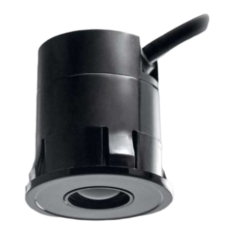
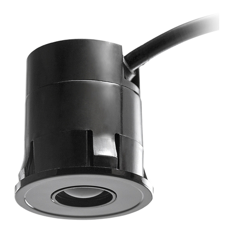
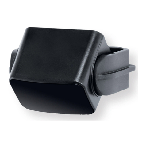
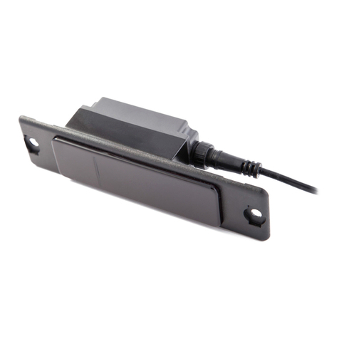
Cedes TOF/Spot Owner's manual

English Pages 2 – 13
Deutsch Seiten 14 – 25
Français Pages 26 – 37
113 009 | 170929 | V 2.0
Installation and Operation Manual
TOF/Spot
CEDES AG is certified according to ISO 9001:2015
TOF/Spot-S TOF/Spot-S
RoHS

TOF/Spot English
2 © CEDES | V 2.0
1. About this manual
This 'TOF/Spot Installation and Operation Manual', with
metric and US measurements is the original version.
The version number is printed at the bottom of each page.
To make sure you have the latest version, visit www.cedes.
com from where this manual and related documents can
be downloaded.
1.1 Measurements
Measurements are, if not stated otherwise, given in
mm (non-bracketed numbers) and inches (numbers in
brackets).
1.2 Related documents
TOF/Spot datasheet en
Part No. 001 206 en
TOF/Spot-S datasheet en
Part No. 001 213 en
Quickguide en de fr es zh, types P, N, C
Part No. 113 495
Quickguide en de fr es zh, type A
Part No. 113 496
Quickguide en de fr es zh, type T
Part No. 113 502
1.3 CEDES headquarter
CEDES AG
Science Park
CH-7302 Landquart
Switzerland
CEDES AG reserves the right to modify or change technical data without prior notice.
Contents
1. About this manual 2
1.1 Measurements 2
1.2 Related documents 2
1.3 CEDES headquarter 2
2. Safety information 3
2.1 Non-intended use 3
3. Symbols, safety messages 3
3.1 Safety messages categories 3
4. Introduction 4
4.1 Application examples 4
4.2 Features of the TOF/Spot 4
4.3 Type description 4
4.4 Category 2 operation (TOF/Spot-S) 4
4.5 Delivery package 5
4.6 TOF/Spot product overview 5
5. Overview 5
5.1 Detection area dimensions 6
5.2 Alignment 7
6. Configuration and operation 7
6.1 P type (Preset) 7
6.2 C type (Automatic calibration) 7
6.3 N type (Potentiometer) 7
6.4 T type (Teach-in) 8
7. In- / Output description 8
7.1 Universal output (relays output) 8
7.2 Logic selector 8
7.3 Analog output 9
7.4 Test input 9
8. Installation 9
8.1 Mounting of snap-in housing 9
9. Electrical connection 10
9.1 Power 10
10. Start-up 10
11. Timing diagrams 11
12. LED signal 12
13. Trouble shooting 12
14. Maintenance 12
15. Disposal 12
16. Product Label 12
17. Technical data 13
18. Dimensions 13

TOF/Spot English
© CEDES | V 2.0 3
2. Safety information
IMPORTANT!
READ BEFORE INSTALLATION!
The TOF/Spot was developed and manufactured using
state-of-the-art systems and technologies. However, injury
and damage to the sensor can still occur.
To ensure safe conditions:
Read all enclosed instructions and information.
Follow the instructions given in this manual carefully.
Observe all warnings included in the documentation
and attached to the sensor.
Do not use the sensor if it is damaged in any way.
Keep the instruction manual on site.
The TOF/Spot should only be installed by authorized and
fully trained personnel! The installer or system integrator is
fully responsible for the safe integration of the sensor. It is
the sole responsibility of the planner and/or installer and/
or buyer to ensure that this product is used according to
all applicable standards, laws and regulations in order to
ensure safe operation of the whole application.
Any alterations to the device by the buyer, installer or user
may result in unsafe operating conditions. CEDES is not
responsible for any liability or warranty claim that results
from such manipulation.
Failure to follow instructions given in this manual and/
or other documents related to the TOF/Spot may cause
customer complaints, serious call backs, damage, injury
or death.
2.1 Non-intended use
The TOF/Spot must not be used for:
• Protection of dangerous machine
• Equipment in explosive atmospheres
• Equipment in radioactive environments
Use only specific and approved safety devices for such
applications, otherwise serious injury or death or damage
to property may occur!
3. Symbols, safety messages
3.1 Safety messages categories
Warning of serious health risks
WARNING
Serious health risks
Highlights critical information for the safe use
of the sensor. Disregarding these warnings
can result in serious injury or death.
Follow the measures highlighted by the
triangle-shaped arrows
Consult the safety information in Chapter
2 of this manual
Caution of possible health risk
CAUTION
Possible health risks
Highlights critical information for the safe
use of the sensor. Disregarding these
warnings can result in injury.
Follow the measures highlighted by the
triangle-shaped arrows
Consult the safety information in Chapter
2 of this manual
Notice of damage risk
NOTICE
Risk of damage
Disregarding these notices can lead to
damage to the sensor, the door controller
and/or other devices.
Follow the measures highlighted by the
triangle-shaped arrows
Symbol Meaning
Single instruction or measures in no
particular order
1.
2.
3.
Sequenced instructions
• List, in no order of importance
àReference to a chapter, illustration or
table within this document
Important Important information for the correct
use of the sensor

TOF/Spot English
4 © CEDES | V 2.0
4. Introduction
The TOF/Spot is a compact yet powerful single-spot
measuring system with the widest range of application
possibilities. It uses Time-of-Flight technology (TOF) to
ensure ultra reliable detection and exact detection range
setting, regardless of the background. This enables a
detection range of up to 6 m (20 ft).
The sensor can measure the exact distance at which
a person or object enters the detection area or it can
simply switch the output at a predefined level. This
means the potential application areas are immense: from
safeguarding the closing door edges of revolving doors,
to optimizing warehouse door opening times, to providing
touchless button functionality. Its small dimensions mean
the TOF/Spot is ideal as a built-in solution.
4.1 Application examples
• Closing edge of revolving doors
• Bus doors
• Closing edge of glass doors
Figure 1: Typical TOF/Spot application environment
4.2 Features of the TOF/Spot
• Exact distance setting, independent of background
• Excellent detection capability
• Universal relay output
• Insensitive to ambient light
• Easy mounting
• Compact and sleek design
• Operating range of up to 6 m
• TÜV approved (TOF/Spot-S, safety version)
• Category 2, PL C (TOF/Spot-S, safety version)
4.3 Type description
Figure 2: TOF/Spot type description
4.4 Category 2 operation (TOF/Spot-S)
The TOF/Spot-S is certified by TÜV according to
EN 13849-1, Cat. 2, PLC ; EN 16005; DIN 18650 and
SIL 1 according to EN 61508.
However, there are certain requirements connected to this
certification:
• The system integrator has to define the correct
electrical connection to the controller to fulfill Cat. 2
operation.
• The sensor must be tested regularly by the controller
through the test input.
• For a safety application, the following mounting
options are valid for a category 2 application:
Figure 3: Horizontal safeguarding with the TOF/Spot-S
TOF/Spot-S
Horizontal
Safeguarded
area
Background
TOF/Spot - a - bb - c - d - e, ff, range
TOF/Spot version
a: - Standard
S Safety
Supply power
ff : AC 12 ... 24 VAC
DC 10 ... 30 VDC
, max. detection range
xx Value in m
Spot size at 2 m range
bb : 40 40 mm x 40 mm
Output
d: U Universal (relay, PNP, NPN)
A Analog
Housing
e: Y Snap-in
TOF/Spot type
c: N Potentiometer
P Preset (value in m)
C Automatic calibration
A Analog
T Teach-in
USB Demo version

TOF/Spot English
© CEDES | V 2.0 5
Figure 4: Inclined safeguarding with the TOF/Spot-S
Figure 5: Vertical safeguarding with the TOF/Spot-S
• In the examples (Figure 3 to Figure 5) the sensor
recognizes the background. A background is needed
to successfully test the sensor with the test input. If the
TOF/Spot-S doesn‘t recognize a background within
the maximal range, the output will be switched to
OBJECT DETECTED.
• The sensor looks towards a flat, plain background
(non-mirroring). There is no need to be perpendicular
to the optical axis.
4.5 Delivery package
A delivery package contains:
• 1 × TOF/Spot sensor with pigtail
• 1 × connection cable (2 m)
• 1 × quick guide manual (depends on the type
ordered)
Figure 6: TOF/Spot delivery package
4.6 TOF/Spot product overview
Figure 7: TOF/Spot overview
1. Snap-in housing
2. Optical window
3. Status LED
4. Connection cable with pigtail
5. Potentiometer
6. Teach-in button and cap
5. Overview
Based on Time-of-Flight technology (TOF), the
TOF/Spot consists of an active infrared emitter and
receiver combined in the same housing. There is one size
of spot-like detection area available which reflects an
exact picture of the safeguarded area.
One output signals the detection of an object within the
detection area. With the A type, there is also a variant
available, which sends the exact distance information to
the controller.
TOF/Spot-S
Safeguarded
area
Background
Inclined
1
3
5
2
4
6
TOF/Spot-S
Safeguarded
area
Background
Vertical

TOF/Spot English
6 © CEDES | V 2.0
Figure 8: Closing edge of revolving doors
Figure 9: Warehouse doors
Figure 10: Closing edge of bus doors
Figure 11: Replaces 'pull-string' door opening
5.1 Detection area dimensions
The maximum detection range is 6 m (20 ft). Object
detection at a range less than 0.2 m (0.7 ft) cannot be
guaranteed.
The TOF/Spot features a detection area of 40 x 40 mm at
2 m (1.57 x 1.57 in at 6.5 ft) range. It reads the correct
distance and switches the output reliably for objects
covering the full beam size (detection area). For objects
being only partially in the detection area, a correct distance
evaluation cannot be guaranteed.
Figure 12: Dimensions of the detection area
Figure 13: Illumination size of the TOF/Spot
As the illumination size is bigger than the detection size,
at 2 m (6.5 ft) range, the TOF/Spot needs at least 20 cm
(7.87 in) space to the next sensor to avoid interference.
40 mm (1.57 in)
at 2 m (6.5 ft)
40 mm (1.57 in)
at 2 m (6.5 ft)
0.2 ... 6 m (0.7 ... 20 ft) 0.2 m
(0.7 ft)
Minimum detection area
Maximum detection area Too large spot size or
too close to the side wall

TOF/Spot English
© CEDES | V 2.0 7
5.2 Alignment
As the detection area of the TOF/Spot looks like a square,
it is important to know where the flat borders and where
the edges are:
Important:
For proper functionality, the remission range of the
background or the object has to be between 2 ... 90%.
Do not use high reflective, retro-reflective or mirroring
backgrounds or objects. They can lead to malfunction
of the sensor due to the emitted beam not being
directly remitted back to the sensor, which leads to
measurements out of the operating range.
6. Configuration and operation
There are different TOF/Spot types available. Some of
them need to be set manually, others are factory set.
IMPORTANT
The sensor uses a ±40 mm (±1.57 in)
hysteresis. The hysteresis is the difference
between the switching points changing the
status from “free field” to “object detected”
and back from “object detected” to “free
field” compared to the nominal limit.
6.1 P type (Preset)
The P type needs no configuration; a specific detection
range is factory set according customer request. Due to
the preset value, the P type is a pure plug-and-play sensor.
Figure 14: Configuration - P type
6.2 C type (Automatic calibration)
The C type cannot be manually calibrated. The sensor
calibrates the background every time it starts up. The C
type has to be fully installed and implemented into the
application before connecting it to the controller.
Functionality:
Every time the sensor starts up (power-up), the TOF/Spot
learns the background information anew during the first
30 s after start-up (the start-up time increases by 30 s).
If the sensor has no background (e.g. it doesn‘t “see”
anything) at start-up, the switching distance is set to 6 m
(20 ft).
Important:
When there is a background, be aware that the set
switching distance is always set about 150 mm (5.9 in)
less than the distance to the background or the object
used for calibration.
A background is used to calibrate the sensor. If there
is none, an object has to be used for simulating the
background during the distance setting or the sensor
calibrates to the maximal range.
The C type is not available as a safety version.
6.3 N type (Potentiometer)
The detection range can be individually set to between
0.2 m and 3 m (0.7 ft and 10 ft) using the potentiometer
located at the rear of the sensor.
Important:
When setting with the potentiometer, use Figure 15 below
as the settings are not printed on the sensor. Take a small
screw driver and turn the potentiometer to the required
position.
Figure 15: Example of an adjustment between 0.2 m and 3 m
Preset:
Set the potentiometer to the limit value before the
sensor is mounted.
Teach:
Mount the sensor at its final position.
Place an object (or person) at the limit distance.
Turn the potentiometer clockwise, starting at the left,
until the LED shines bright.
Turn it back slowly until the LED dims.
Now the limit is set to the correct distance.
Preset range
LED bright
LED dimmed
0.75 m
(2.46 ft)
1.5 m
(5 ft) 2.25 m
(7.34 ft)
0.2 m
(0.7 ft) 3 m
(10 ft)

TOF/Spot English
8 © CEDES | V 2.0
Figure 16: Configuration - N type
6.4 T type (Teach-in)
The T type features a teach-in function that can be initiated
in two ways:
1. Exchange of the polarity of the supply voltage
(brown wire to GND and blue wire to USP)
With the exchanged connection of GND and USP, the
sensor is put into a setting mode and learns the distance
to the background. The status LED starts to blink. To
indicate that the calibration is finished, the sensor stops
blinking and stays red for about 30 s. Now the wiring of
the TOF/Spot has to be adjusted according to the electrical
connections (brown wire to USP and blue wire to GND).
The mode is an endless loop of 30 s setting time (blinking
LED) followed by a 30 s break (red LED). In this mode, the
sensor cannot work.
Figure 17: Configuration T type - exchange of the polarity
Please note: Only with DC supply possible
2. Setting with the teach-in button
There is a button located at the back of the sensor. When
the teach-in button is pressed for at least 2 s, the LED blinks
for 30 s; the detection area (distance to the background
minus 150 mm (5.9 in) is saved and the LED dims. As soon
as a person or object enters the detection area, the sensor
switches the output.
The set switching distance can only be changed by
pressing the teach-in button again.
Figure 18: Configuration T type with the teach-in button
Important:
Be aware that the set switching level is always about
150 mm (5.9 in) above the background.
A background within the maximal detection range
is used to calibrate the sensor. If there is none, an
object has to be used for simulating a background. A
calibration into nothingness does not work.
When the power is switched off the sensor remembers
the last setting as the switching distance. This distance
can only be changed by doing the setting process
again.
7. In- / Output description
There are different possibilities of in- and outputs. Please
be aware that not all variants can be used with every type
e.g. the A type is only available with an analog output.
7.1 Universal output (relays output)
Available for:
DC supply: Types P, N, C, T; with logic selector.
AC supply: Types P, N, T; no logic selector; output
“normally closed (NC)”
The TOF/Spot features a universal (relays) output. With
the help of the logic selector, the output signal can be
configured according to the controller requirements for
“normally open” or “normally closed” operation.
7.2 Logic selector
Available for:
DC supply: Types P, N, C, T
Important: The logic selector has to have a DC signal.
An AC signal will not work.
Figure 19: Logic selector
LED bright
LED dimmed
0.75 m
(2.46 ft)
1.5 m
(5 ft) 2.25 m
(7.34 ft)
0.2 m
(0.7 ft) 3 m
(10 ft)
Check & operation
Calibration
blue
+USP brown
GND
blue
+USP brown
GND
blue
GND brown
+USP
dimmed
dimmed dimmed
bright
dimmed
blinking ≤ 30 s
Sensor Phase
LED
3
465
1 2
Offset
150 mm
< 30 s
Output A and B
NC (normally closed)
Logic selector connected to
GND (0 V) or not connected
NO (normally open)
Logic selector connected to USP
Contact
open
Contact
closed
Contact
open
Contact
closed
Offset
150 mm
Start-up:
dimmed or
bright
dimmed dimmed
bright
blinking blinking ≤ 30 s
Check & operation
Calibration
Sensor Phase
LEDButton
1 2 3
46
5
≥2 s
Push Release

TOF/Spot English
© CEDES | V 2.0 9
7.3 Analog output
Available for:
DC supply: Type A; no logic selector
The A type has an analog current output that is directly
related to the measured distance to the object in the
detection field. The value of the analog output has a range
of 4 ... 20 mA and corresponds directly to the measured
distance.
The value of the current output in regards of the distance
is as follows:
Figure 20: Analog output
Theloadneedstobeamaximumof250Ωandleadstoa
respective voltage output of 1 … 5 VDC.
7.4 Test input
Available for:
All TOF/Spot-S with DC supply
The logic of the test signal is being recognized
automatically. This works as follows:
1. Connect the TOF/Spot-S with the controller.
2. Power up the controller.
3. The sensor recognizes the voltage level at the test input
during the power up time and sets the test to inactive.
From this point on, this level is used as “test inactive”.
4. When the voltage level of the test input changes,
the sensor will recognize it as test signal (test active).
The sensor switches the output and the status LED
to “OBJECT DETECTED” (see Figure 25, Timing
diagram).
5. As soon as the voltage level of the test input switches
back to the initial level, the sensor returns to normal
operating mode. The output voltage level switches
back only if the background or an object is within
the operating range, but outside the switching level
(Detection field FREE).
Important:
A test sequence must be implemented by the system
integrator to achieve safe operation according Cat. 2.
The test signal has to be a DC signal, an AC signal
will not work.
The test can only be used if the sensor has a permanent
background. If not, the test cannot be carried out.
8. Installation
It is recommended to carry out the system installation
according to the following steps:
1. Check if the scope of delivery is complete.
2. Mark clearly that the modifying system is out of service
and switch off main power and door control unit.
3. The installation place needs to fulfill the criteria
detailed in Chapter 5.1.
4. Drill a hole at the required position (see drilling
template for flush and surface mounting).
5. If needed, mount the mounting bracket.
6. Screw or snap in the sensor at the defined position.
7. Connect the TOF/Spot with the controller.
8.1 Mounting of snap-in housing
The mounting hole recommended for flush mounting is 30
to 31 mm. The sheet thickness cannot be greater 3 mm.
Figure 21: Mounting of snap-in housing
0.2
(0.7 ft)
20
4
Distance [m]
Current [mA]
Standard version
3.0 / 6.0
(10.0 / 20.0 ft)
Safety version
30 mm ± 0.5
(1.18 in ± 0.019 )
0.3 ... 3 mm
(0.011 ... 0.12 in)

TOF/Spot English
10 © CEDES | V 2.0
9. Electrical connection
There are different possibilities according to supply power
and output chosen.
9.1 Power
There are two variants, one with a DC power supply (10
… 30 VDC) and one with an AC power supply (12 … 24
VAC). The two variants have to be ordered accordingly.
Outputs available for DC and AC supply power:
Relay output (Universal output; types P, C, N, T)
Figure 22: Solid-state relay output (DC supply)
Figure 23: Solid-state relay output (AC supply)
Important:
Output A and Output B are interchangeable
Any unconnected (n.c.) wires have to be separated and
isolated
* If test input not used - connect with USP or GND
Outputs available with a DC supply power only:
Figure 24: Analog output
Important:
Any unconnected (n.c.) wires have to be separated and
isolated. No termination needed.
Only the relay output is available in combination with
an AC supply power.
* If test input not used - connect with USP or GND
10. Start-up
1. Switch on mains and power up the door control unit.
2. Check if LED lights up.
3. Check the distance setting and the reaction of the
sensor, including the status LED, by placing a hand
into the detection area at different heights.
4. Perform a test run with the controller using the test
input.
TOF/Spot
AC supply - Universal
Controller
∼Vcc (12 ... 24 VAC)
n.c.
n.c.
Output A
Output A = Output B
n.c. = not connected and isolated
Output B
black
brown
green
blue
white
gray
TOF/Spot
DC supply - Analog output
Controller
USP (10 ... 30 VDC)
GND (0 V)
Test input*
n.c.
Analog output (4 ... 20 mA)
n.c. = not connected and isolated
* = If test input not used - connect
with U
SP
or GND
Analog GND
black
brown
green
blue
white
gray
TOF/Spot
DC supply - Universal
Controller
USP (10 ... 30 VDC)
GND (0 V)
Test input*
Logic selector
Output A
Logic selector:
NO = U
SP
NC = GND or n.c.
n.c. = not connected and isolated
* = If test input not used - connect
with U
SP
or GND
Output A = Output B
Output B
black
brown
green
blue
white
gray

TOF/Spot English
© CEDES | V 2.0 11
11. Timing diagrams
Figure 25: Timing diagram for relay output
Figure 26: Timing diagram for the analog output
* Teachable at start-up
t1t3t4
t2
t5t6
t7
XX
XX
XX
NO (normally open)
Ausgang
Stromversorgung
LED-Status
Testeingang*
NC (normally closed)
Ausgang
TEST
Objekterkennung
Leuchtet
Aus Gedimmt Gedimmt
Leuchtet Leuchtet
Ein
Aus
Objekt
Kein Objekt
Inaktiv
Aktiv
Geschlossen
Offen
Geschlossen
Offen
t1
t2
t3t4
t7
t5t6
Power supply
Test input*
Output
TEST
Distance to object
On
Off
Inactive
Active
20 mA
4 mA
3.0 / 6.0 m
0.2 m
Time Value
Start-up time test input t1< 200 ms
Power-on time t21,000 ms
Response time t3≤60ms
Release time t4≤60ms
Test response time t55 ms
Test release time t6≤60ms
Test time t7> 60 ms
Time Value
Test input HIGH
LOW
10 VDC ... USP
0 ... 3 VDC
Logic selector
input
NC: normally closed
NO: normally open
0 ... 3 VDC
10 VDC ... USP
Output A and B
(relay)
Voltage pin to GND
Voltage between pins
Current
-30 ... +30 V
-60 ... +60 V
< ±150 mA
Analog output
Current
Voltage
Input resistance
4 ... 20 mA
< 6 VDC
<250Ω
Table 1: General timing table Table 2: General value table

TOF/Spot English
12 © CEDES | V 2.0
12. LED signal
13. Trouble shooting
If the problem persists, please contact your local CEDES
representative (www.cedes.com).
14. Maintenance
Although the TOF/Spot does not need regular
maintenance, a periodical functional check is strongly
recommended as follows:
Check the mounting position and detection area of the
sensor
Clean the optical window with a soft towel and a little
soapy water
15. Disposal
The TOF/Spot should only be replaced if a similar
protection device is installed. Disposal should be done
using the most up-to-date recycling technology according
to local regulations and laws. There are no harmful
materials used in the design and manufacture of the
sensor. Traces of such dangerous materials may be found
in the electronic components but not in the quantities that
are harmful.
16. Product Label
Each TOF/Spot and TOF/Spot-S is labelled as below.
It contains following information:
Figure 27: Product label - TOF/Spot (standard version)
Figure 28: Product label - TOF/Spot-S (safety version)
Lot No.:
yymmdd: year (2 digits), month, day
mmmmmmmm: manufacturing job number
eeeee: employee number responsible for final test
cccccc: incremental number
LED status Description
LED off No power
LED dimmed red No object detected
LED bright red Object detected or test active
LED blinking
(C and T type only) Distance setting active
Status Action
LED off Check supply power
Check electrical
connections
Object in the
safeguarded area and
LED dimmed red
Check distance setting
Check alignment
No object in the
safeguarded area and
LED bright red
Check electrical
connections
Check distance setting
Check alignment
The output doesn’t
switch after
starting test
Is an object in the
detection area?
Check electrical
connections
The output doesn’t
switch back after ending
of test
Sensor doesn’t see a
background
Is an object in the
detection area?
Check distance setting
NOTICE
Damage to the optical window
Never use any solvents, cleaners
or mechanically abrasive towels or
highpressure water to clean the sensors.

TOF/Spot English
© CEDES | V 2.0 13
17. Technical data
Optical
Operating range
- Types P, C, T and A 0.2 ... 6 m (0.7 ... 20 ft)
- Types N and A 0.2 ... 3 m (0.7 ... 10 ft)
Active light spot at 2 m distance 40 mm × 40 mm
(1.57 in × 1.57 in
at 6.5 ft)
Switching level
- Types C and T 0.15 m (5.9 in)
from background
Measurement precision ±5% at 2 m (at 6.5 ft)
±10 cm (3.93 in)
over the whole range
Max. ambient light 100,000 Lux
Mechanical
Dimensions Ø 29.5 × 35.8 mm
(1.16 × 1.41 in)
Housing material Polycarbonate
Housing color Black
Enclosure rating IP65
Operatingtemperaturerange −40°C...+60°C
Relative humidity 0 ... 95%
(non-condensing)
Electrical
Supply voltage USP 10 ... 30 VDC /
12 ... 24 VAC
Current consumption at 24 VDC 50 mA
Peak current consumption 500 mA
during power-up at 24 VDC
Output Solid-state relay, analog
Max. switching voltage 60 V
Max. switching current 150 mA
Max power-up time 1 s
Max. response time 60 ms
Test response time 5 ms
Connection cable and electrical connection
Sensor
Length 0.25 m
Connection M8, 6-pin
Diameter Ø 4.2 mm
Material PVC, black
Plug color Blue
Connection cable
Length 2 m (other lengths on request)
Connection M8, 6-pin
Diameter Ø 4.2 mm
Material PVC, black
Plug color Blue
Wires AWG26
•brown +USP
•black OutputAandanalogoutput
•green OutputBandanalogGND
•blue GND(0V)/-USP
•white Testinput
•gray Logicselector
General
EMC emission EN 61000-6-3:2007,
EN 12015:2014
EMC immunity EN 61000-6-2:2005,
EN 12016:2013 +A1:2008
Vibration EN 60068-2-6:2008
Shock EN 60068-2-27:2009
Change of temperature EN 60068-2-14:2009
Safety rules for the DIN EN 81-1/-2:2010
construction and
installation of lifts
Part 20: Passenger and DIN EN 81-20:2011
goods passenger lifts
Certificates CE, TÜV
TOF/Spot-S
Applicable standards EN ISO 13849-1:2008,
Cat. 2 PL C*
EN 12978:2009
DIN 18650:2010, clause 5.7.4
EN 16005:2013,clause 4.6.8
EN 61508:2010, SIL1*
* only when the sensor is pointed towards a background
within the max. operating range
18. Dimensions
Measurements all dimensions in mm (inches)
35.8 (1.41)
Ø 34 (1.34)
Ø 29.5 (1.16)

TOF/Spot Deutsch
14 © CEDES | V 2.0
1. Über diese Anleitung
Die Originalversion dieser Anleitung ist “TOF/Spot
Installation and Operation Manual” mit metrischer und
US Vermassung.
Die Versionsnummer ist am unteren Rand jeder Seite
abgedruckt.
Die aktuelle Version dieser Anleitung und verwandte
Dokumente können auf www.cedes.com heruntergeladen
werden.
1.1 Massangaben
Alle Längen sind, wenn nicht anders angegeben, in
Millimeter (mm) vermasst.
1.2 Verwandte Dokumente
TOF/Spot Datenblatt de
Art. Nr. 001 206 de
TOF/Spot-S Datenblatt de
Art. Nr. 001 213 de
Quickguide en de fr es zh, Typen P, N, C
Art. Nr. 113 495
Quickguide en de fr es zh, Typ A
Art. Nr. 113 496
Quickguide en de fr es zh, Typ T
Art. Nr. 113 502
1.3 CEDES Hauptsitz
CEDES AG
Science Park
CH-7302 Landquart
Schweiz
Inhalt
1. Über diese Anleitung 14
1.1 Massangaben 14
1.2 Verwandte Dokumente 14
1.3 CEDES Hauptsitz 14
2. Sicherheitshinweise 15
2.1 Nicht bestimmungsgemässe Verwendung 15
3. Symbole und Sicherheitshinweise 15
3.1 Warnhinweiskategorien 15
4. Einleitung 16
4.1 Anwendungsbeispiele 16
4.2 Merkmale von TOF/Spot 16
4.3 Typendefinition 16
4.4 Kategorie 2 Betrieb (TOF/Spot-S) 16
4.5 Lieferumfang 17
4.6 TOF/Spot Produktübersicht 17
5. Übersicht 17
5.1 Abmessungen des Erfassungsbereichs 18
5.2 Ausrichtung 19
6. Konfiguration und Betrieb 19
6.1 Typ P (Preset) 19
6.2 Typ C (Automatische Kalibrierung) 19
6.3 Typ N (Potentiometer) 19
6.4 Typ T (Teach-in) 20
7. Ein- und Ausgänge 20
7.1 Universalausgang (Relaisausgang) 20
7.2 Logik-Selektor 20
7.3 Analogausgang 21
7.4 Testeingang 21
8. Montage 21
8.1 Montage Snap-in Gehäuse 21
9. Elektrische Anschlüsse 22
9.1 Versorgungsspannung 22
10. Inbetriebnahme 22
11. Zeitdiagramme 23
12. LED-Anzeigen 24
13. Fehlerbehebung 24
14. Wartung 24
15. Entsorgung 24
16. Produktetikette 24
17. Technische Daten 25
18. Abmessungen 25

TOF/Spot Deutsch
© CEDES | V 2.0 15
2. Sicherheitshinweise
WICHTIG!
VOR DER MONTAGE LESEN!
TOF/Spot wurde mit den neuesten Systemen und
Technologien entwickelt und hergestellt. Trotzdem können
Schäden und Verletzungen auftreten.
Für sichere Arbeits- und Betriebsbedingungen:
Alle relevanten Dokumente lesen.
Alle Anweisungen in dieser Anleitung befolgen.
Alle Warnungen in dieser Anleitung und auf dem
Gerät beachten.
Beschädigte Sensoren nicht mehr benutzen.
Bedienungsanleitung beim Sensor aufbewahren.
TOF/Spot darf nur von ausgebildetem und autorisiertem
Fachpersonal installiert werden! Der Monteur oder
Systemintegrator trägt die volle Verantwortung für die
sichere Montage des Sensors. Der Planer und/oder
Monteur und/oder Käufer tragen die volle Verantwortung
für die Einhaltung aller relevanten Gesetze und Normen,
die dieses Produkt betreffen, um einen sicheren Betrieb
der gesamten Anwendung sicherzustellen.
Sämtliche Änderungen an der Vorrichtung durch
Käufer, Monteur oder Benutzer können zu unsicheren
Betriebsbedingungen führen. CEDES übernimmt für
Schäden, die durch solche Manipulationen entstanden
sind, keine Haftung oder Garantieansprüche.
Das Nichtbefolgen der Anweisungen im vorliegenden
Handbuch und/oder anderen Dokumenten zu TOF/Spot
kann Kundenbeschwerden, Rückrufaktionen, Schäden
und Verletzungen bis hin zum Tod nach sich ziehen.
2.1 Nicht bestimmungsgemässe
Verwendung
TOF/Spot darf nicht eingesetzt werden:
• Absicherung von gefährlichen Maschinen
• Anlagen in explosiven Atmosphären
• Equipment in radioactive environments
Für Anwendungen dieser Art dürfen nur spezielle, dafür
zugelassene Sicherheitsvorrichtungen eingesetzt werden.
Andernfalls kann dies zu schweren Verletzungen,
Todesfällen oder Sachschäden führen!
3. Symbole und
Sicherheitshinweise
3.1 Warnhinweiskategorien
Warnung vor schwerwiegenden Gesundheits-
gefahren
Hinweis auf mögliche Gesundheitsgefahren
Hinweis auf Gefahr von Sachschäden
Symbol Bedeutung
Einzelne Handlungsaufforderung ohne
bestimmt Reihenfolge
1.
2.
3.
Handlungsaufforderung in einer
bestimmten Reihenfolge
• Aufzählungspunkt, Reihenfolge ist
unerheblich
àVerweis auf ein Kapitel, eine
Abbildung oder Tabelle in diesem
Dokument
Wichtig Wichtige Informationen zur richtigen
Nutzung des Sensors
WARNUNG
Schwerwiegende Gesundheits-
gefahren
Enthält wichtige Informationen zur sicheren
Nutzung des Sensors. Nichtbeachten dieser
Warnungen kann zu schweren Verletzungen
oder zum Tod führen.
Handlungsaufforderungen nach drei-
eckigen Pfeilen befolgen
Die Sicherheitshinweise in Kapitel 2 dieser
Anleitung beachten
VORSICHT
Mögliche Gesundheitsgefahren
Weist auf wesentliche Informationen zum
sicheren Gebrauch des Sensors hin.
Nichtbeachten dieser Hinweise kann zu
Verletzungen führen.
Handlungsaufforderungen nach drei-
eckigen Pfeilen befolgen
Die Sicherheitshinweise in Kapitel 2 dieser
Anleitung beachten
HINWEIS
Gefahr von Sachschäden
Nichtbeachten dieser Hinweise kann zu
Schäden am Sensor, der Türsteuerung und/
oder anderen Einrichtungen führen.
Handlungsaufforderungen nach drei-
eckigen Pfeilen befolgen

TOF/Spot Deutsch
16 © CEDES | V 2.0
4. Einleitung
TOF/Spot ist ein kompaktes und dennoch leistungsstarkes
Messsystem mit vielen Anwendungsmöglichkeiten. Es
nutzt die Time-of- Flight-Technologie, die eine höchst
zuverlässige Erkennung und eine genaue Einstellung
der Detektionsschwelle gewährleistet – unabhängig vom
Hintergrund. Eine Reichweite von bis zu 6 m ist möglich.
Der Sensor misst die genaue Höhe, bei der eine Person
oder ein Objekt den Erfassungsbereich betritt bzw.
kann einfach den Ausgang bei einer vordefinierten
Höhe schalten. Dadurch ergeben sich unzählige
Anwendungsmöglichkeiten von der Sicherung der
Nebenschliesskanten von Drehflügeltüren, über
die Messung von Flüssigkeitsständen bis hin zu
berührungsfreien Schaltern. Mit seinen geringen
Abmessungen ist der TOF/Spot-Sensor die ideale
Einbaulösung.
4.1 Anwendungsbeispiele
• Absicherung der Nebenschliesskante von
Drehflügeltüren
• Absicherung von Bustüren
• Absicherung der Nebenschliesskante von Glastüren
Abb 1: Typische TOF/Spot Anwendungsumgebungen
4.2 Merkmale von TOF/Spot
• Genaue Einstellung des Erfassungsbereichs,
unabhängig vom Hintergrund
• Hervorragende Objekterkennung
• Universeller Relaisausgang
• Unempfindlich gegen Fremdlicht
• Einfache Montage
• Kompaktes und elegantes Design
• Reichweite bis zu 6 m
• TÜV zertifiziert (TOF/Spot-S, Safety-Version)
• Kategorie 2, PL C (TOF/Spot-S, Safety-Version)
4.3 Typendefinition
Abb 2: TOF/Spot Typendefinition
4.4 Kategorie 2 Betrieb (TOF/Spot-S)
Der TOF/Spot-S ist TÜV-geprüft nach EN 13849-1, Kat. 2,
PLC sowie EN 16005 und DIN 18650.
Mit dieser Zertifizierung sind jedoch gewisse
Anforderungen verbunden:
• Für den Kategorie 2 Betrieb muss der System-
integrator den korrekten elektrischen Anschluss
festlegen.
• Der Sensor ist regelmässig über den Testeingang
durch den Kontroller zu überprüfen.
• Für Sicherheitsanwendungen der Kategorie 2 sind
folgende Einbaumöglichkeiten gegeben:
Abb 3: Horizontale Sicherheitsanwendung mit TOF/Spot-S
TOF/Spot-S
Horizontal
Überwachter
Bereich
Hintergrund
TOF/Spot - a - bb - c - d - e, ff, Reichweite
TOF/Spot-Version
a: - Standard
S Safety
Versorgungsspannung
ff : AC 12 ... 24 VAC
DC 10 ... 30 VDC
, Max. Reichweite
xx Wert in m
Lichtkegel in 2 m Entfernung
bb : 40 40 mm x 40 mm
Ausgang
d: U Universal (Relais, PNP, NPN)
A Analog
Gehäuse
e: Y Snap-in
TOF/Spot-Typ
c: N Potentiometer
P Preset (Wert in m)
C Automatische Kalibrierung
A Analog
T Teach-in
USB Demoversion

TOF/Spot Deutsch
© CEDES | V 2.0 17
Abb 4: Geneigte Sicherheitsanwendung mit TOF/Spot-S
Abb 5: Vertikale Sicherheitsanwendung mit TOF/Spot-S
• In den beschriebenen Beispielen (Abb. 3 bis Abb.
5) erkennt der Sensor den Hintergrund. Für eine
erfolgreiche Prüfung des Sensors über den Testeingang
wird ein Hintergrund benötigt. Erkennt der TOF/
Spot innerhalb der maximalen Reichweite keinen
Hintergrund, schaltet der Ausgang auf OBJEKT
ERKANNT.
• Der Sensor ist auf einen flachen, ebenen Hintergrund
(nicht spiegelnd) ausgerichtet. Ein rechter Winkel zur
optischen Achse ist nicht notwendig.
4.5 Lieferumfang
Ein Lieferumfang enthält:
• 1 × TOF/Spot-Sensor mit Stecker
• 1 × Anschlusskabel (2 m)
• 1 × Quick Guide Anleitung (abhängig von bestelltem
Typ)
Abb 6: Lieferumfang TOF/Spot
4.6 TOF/Spot Produktübersicht
Abb 7: Übersicht TOF/Spot
1. Snap-in-Gehäuse
2. Optisches Fenster
3. Status-LED
4. Anschlusskabel mit Stecker
5. Potentiometer
6. Teach-in-Taster und Deckel
5. Übersicht
Der TOF/Spot basiert auf der Time-of-Flight-Technologie
(TOF) und besteht aus einem aktiven Sender und einem
Empfänger, die in einem Gehäuse untergebracht sind. Für
den punktförmigen Erfassungsbereich steht eine Grösse
zur Verfügung, die ein exaktes Bild des überwachten
Bereichs wiedergibt.
Der Ausgang signalisiert die Erfassung eines Objekts
innerhalb des Erfassungsbereichs. Der Typ A bietet
zusätzlich die Möglichkeit, genaue Entfernungsangaben
an den Kontroller zu übermitteln.
TOF/Spot-S
Überwachter
Bereich
Hintergrund
Geneigt
1
3
5
2
4
6
TOF/Spot-S
Überwachter
Bereich
Hintergrund
Vertikal

TOF/Spot Deutsch
18 © CEDES | V 2.0
Abb 8: Nebenschliesskante - Glastüren
Abb 9: Lagerhallentore
Abb 10: Nebenschliesskante - Bustüren
Abb 11: Kontaktloser Türöffner (Zugseil-Alternative)
5.1 Abmessungen des Erfassungsbereichs
Die maximale Reichweite beträgt 6 m. Die Erkennung von
Objekten in einer Entfernung von weniger als 0.2 m kann
nicht garantiert werden.
Bei zwei Metern Distanz misst der Erfassungsbereiches
TOF/Spot 40 mm x 40 mm. Der Sensor liest die korrekte
Entfernung aus und schaltet bei Objekten, die den vollen
Querschnitt des Strahls (Erfassungsbereich) abdecken,
zuverlässig den Ausgang. Bei Objekten, die sich nur
teilweise im Erfassungsbereich befinden, kann eine
korrekte Abstandsmessung nicht garantiert werden.
Abb 12: Abmessungen des Erfassungsbereichs
Abb 13: Beleuchtungsgrösse des TOF/Spot
Ist die Beleuchtungsgrösse bei zwei Meter Distanz grösser
als der Erfassungsbereich, benötigt TOF/Spot mindestens
20 cm Abstand zum nächsten Senor, um Störungen zu
vermeiden.
40 mm bei 2 m
40 mm bei 2 m
0.2 ... 6 m 0.2 m
Minimaler Erfassungsbereich
Maximaler Erfassungsbereich Punkt zu gross oder
zu nah an der Seitenwand

TOF/Spot Deutsch
© CEDES | V 2.0 19
5.2 Ausrichtung
Der Erfassungsbereich des TOF/Spot ist quadratisch,
daher ist es wichtig zu wissen, wo sich die flachen Ränder
und Kanten befinden:
Wichtig:
Um eine einwandfreie Funktion gewährleisten zu
können, muss der Remissionsgrad des Hintergrunds
oder des Objekts zwischen 2 und 90 % liegen.
Stark reflexive, retroreflexive oder spiegelnde
Hintergründe oder Objekte dürfen nicht verwendet
werden. Diese remittieren den Strahl nicht direkt zurück
zum Sensor, sodass Fehlfunktionen des Sensors durch
Messungen ausserhalb des Arbeitsbereichs auftreten.
6. Konfiguration und Betrieb
Der TOF/Spot ist in verschiedenen Versionen lieferbar.
Einige müssen manuell eingerichtet werden, andere sind
bereits ab Werk voreingestellt.
6.1 Typ P (Preset)
Für den Typ P ist keine Konfiguration erforderlich, ein
spezifischer Erfassungsbereich wird nach Kundenvorgabe
ab Werk eingestellt. Durch diese Voreinstellung ist der Typ
P ein reiner Plug-and-Play- Sensor.
Abb 14: Konfiguration - Typ P
6.2 Typ C (Automatische Kalibrierung)
Der Typ C kann nicht manuell kalibriert werden,
sondern der Sensor kalibriert den Hintergrund bei jedem
Einschalten. Vor dem Anschluss an den Controller muss
der Typ C komplett installiert und in die Anwendung
implementiert sein.
Funktionsweise:
Bei jedem Einschalten (Aufstarten) erfasst der TOF/Spot
während der ersten 30 Sekunden nach dem Einschalten
die Hintergrundinformationen neu (Einschaltzeit erhöht
sich um 30 s). Hat der Sensor beim Aufstarten keinen
Hintergrund (er "sieht" nichts), wird die Schaltdistanz auf
6 m eingestellt.
Wichtig:
Bei Vorhandensein eines Hintergrunds muss
berücksichtigt werden, dass die Schaltdistanz generell
ca. 150 mm kürzer als der Abstand zum Hintergrund
oder dem für die Kalibrierung genutzten Objekt
eingestellt wird.
Ein Hintergrund wird zur Kalibrierung des Sensors
verwendet. Ist kein Hintergrund vorhanden, wird die
für die Abstandseinstellung anhand eines Objekts ein
Hintergrund simuliert oder der Sensor kalibriert sich
auf die maximale Reichweite.
Der Typ C ist nicht als Sicherheitsversion lieferbar.
6.3 Typ N (Potentiometer)
Der Erfassungsbereich kann mithilfe des Potentiometers
an der Rückseite des Sensors individuell auf einen Abstand
zwischen 0.2 und 3 m eingestellt werden.
Wichtig:
Zum Einstellen des Potentiometers nachfolgende Abb. 15
verwenden, da die Einstellungen nicht auf dem Sensor
aufgedruckt sind. Das Potentiometer mit einem kleinen
Schraubendreher in die gewünschte Position bringen.
Abb 15: Beispiel für eine Einstellung zwischen 0.2 und 3 m
Voreinstellung (Preset):
Vor Anbringen des Sensors das Potentiometer auf den
Grenzwert einstellen.
Teachen:
Sensor an seiner endgültigen Einbauposition
anbringen.
Eine Person oder einen Gegenstand an der Grenze
der Reichweite positionieren.
Von links startend, das Potentiometer im Uhrzeigersinn
drehen bis die LED hell leuchtet.
Anschliessend langsam zurückdrehen, bis das
Leuchten der LED schwächer wird.
Der Grenzwert ist damit auf den korrekten Abstand
eingestellt.
WICHTIG
Der Sensor verwendet eine Hysterese von ±40
mm. Hysterese ist die Differenz zwischen den
Schaltpunkten, die von "freies Feld" auf "Objekt
erkannt" und zurück von "Objekt erkannt" auf
"freies Feld" schalten, verglichen mit dem
nominalen Grenzwert.
Fixe Reichweiten-
einstellung
LED leuchtet
LED gedimmt
0.75 m
1.5 m
2.25 m
0.2 m 3 m

TOF/Spot Deutsch
20 © CEDES | V 2.0
Abb 16: Konfiguration - Typ N
6.4 Typ T (Teach-in)
Der Typ T verfügt über eine Teach-in-Funktion, die auf
zwei Arten initialisiert werden kann:
1. Polarität der Versorgungsspannung umkehren
(braunes Kabel an GND und blaues an USP)
Durch das Vertauschen der Anschlüsse von GND und USP
wird der Sensor in einen Einrichtmodus geschaltet und
lernt die Entfernung zum Hintergrund. Die Statusanzeige
beginnt zu blinken. Wenn der Sensor aufhört zu blinken
und ca. 30 s lang rot leuchtet, ist die Kalibrierung
abgeschlossen und die Verkabelung des TOF/Spot kann
entsprechend angepasst werden (braunes Kabel an USP
und blaues Kabel an GND).
Der Modus besteht in einer Endlosschleife von 30 s
Einrichtzeit (blinkende LED) und anschliessend 30 s
Pause (rote LED). In diesem Modus ist der Sensor nicht
funktionsfähig.
Abb 17: Konfiguration Typ T - Spannungswechsel
2. Einrichtung mit der Teach-in-Taste
An der Rückseite des Sensors befindet sich eine Taste.
Wird die Teach-in-Taste mindestens 2 s lang gedrückt,
blinkt die LED für 30 s, der Erfassungsbereich (Abstand
zum Hintergrund abzüglich 150 mm) wird gespeichert
und die LED leuchtet schwächer. Sobald eine Person oder
ein Objekt in den Erfassungsbereich gelangt, schaltet der
Sensor den Ausgang um.
Die eingestellte Schaltentfernung kann nur durch erneutes
Drücken der Teach-in-Taste geändert werden.
Abb 18: Configuration Typ T mit dem Teach-in-Taster
Wichtig:
Nicht vergessen, dass der eingestellte Schaltabstand
(Offset) immer ca.150 mm vor dem Hintergrund liegt.
Mithilfe eines Hintergrunds innerhalb des maximalen
Erfassungsbereichs kann der Sensor kalibriert
werden. Ein fehlender Hintergrund kann mithilfe eines
Gegenstands simuliert werden. Eine Kalibrierung ins
Nichts ist nicht möglich.
Beim Abschalten speichert der Sensor die letzte
Einstellung als Schaltentfernung. Dieser Abstand kann
nur durch einen erneuten Einstellvorgang geändert
werden.
7. Ein- und Ausgänge
Es gibt mehrere Möglichkeiten für Ein- und Ausgänge.
Bitte beachten, dass nicht alle Varianten für jeden Typ
verwendet werden können. Typ A ist beispielsweise nur mit
Analogausgang lieferbar.
7.1 Universalausgang (Relaisausgang)
Verfügbar für:
DC Spannung: Typen P, N, C, T; mit Logik-Selektor
AC Spannung: Typen P, N, T; kein Logik-Selektor;
Ausgang “normally closed (NC)”
Der TOF/Spot ist mit einem Universalausgang (Relais)
ausgestattet. Mithilfe des Logik-Selektors kann das
Ausgangssignal entsprechend den Anforderungen für
einen “normally open” oder “normally closed” Betrieb
eingerichtet werden.
7.2 Logik-Selektor
Verfügbar für:
DC Spannung: Typen P, N, C, T
Wichtig: Der Logikselektor benötigt ein DC-Signal. Ein
AC-Signal funktioniert nicht.
Abb 19: Logik-Selektor
Check & operation
dimmed dimmed
bright
Kalibrierung
blau
+USP braun
GND
blau
+USP braun
GND
blau
GND braun
+USP
Gedimmt Gedimmt
Blinkend ≤ 30 s
Sensor Phase
LED Sensor Phase
LED
3
465
1 2
Offset
150 mm
< 30 s
Ausgang A und B
NC (normally closed)
Logik-Selektor mit GND (0 V) verbunden
oder nicht angeschlossen
NO (normally open)
Logik-Selektor mit USP verbunden
Kontakt
offen
Kontakt
geschlossen
Kontakt
offen
Kontakt
geschlossen
LED leuchtet
LED gedimmt
0.75 m
1.5 m
2.25 m
0.2 m 3 m
Gedimmt Gedimmt
Leuchtend
Test & Betrieb
1 2 3
46
5
≥2 s
Offset
150 mm
Aufstarten:
Gedimmt oder
leuchtend
Blinkend Blinkend ≤ 30 s
Kalibrierung
Sensor Phase
LEDTaster
Drücken Loslassen
Other manuals for TOF/Spot
3
Table of contents
Languages:
Other Cedes Accessories manuals

Cedes
Cedes TLS 600 User manual

Cedes
Cedes Mini-32-NA-TKE User manual

Cedes
Cedes GridScan/Pro User manual

Cedes
Cedes TLS 600 User manual

Cedes
Cedes TOF/Start-EA User manual

Cedes
Cedes TOF/Spot User manual

Cedes
Cedes TLS 500 User manual

Cedes
Cedes TOF/TaxI User manual

Cedes
Cedes TOFniva User manual

Cedes
Cedes GridScan/Pro SI User manual

Cedes
Cedes TOF/Spot User manual

Cedes
Cedes TOF/Spot-car detection User manual

Cedes
Cedes IMS 100 User manual

Cedes
Cedes ELS 263 User manual

Cedes
Cedes TOF/Spot-Safety User manual

Cedes
Cedes TPS User manual

Cedes
Cedes TLS 500 User manual

Cedes
Cedes TOF User manual

Cedes
Cedes cegard/Max-154 User manual

Cedes
Cedes ELS 300 User manual