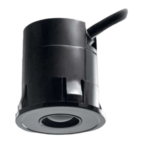
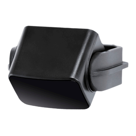
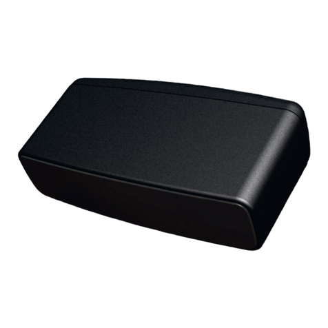
Cedes TLS 500 User manual

CEDES
© CEDES Version 1.1 3th May 2011 Part No. 110 605en
TLS 500
… small, compact, versatile
English
IMPORTANT NOTE
FOLLOW THE INSTRUCTIONS GIVEN IN THIS MANUAL CAREFULLY. FAILURE TO DO
SO MAY CAUSE CUSTOMER COMPLAINTS AND SERIOUS CALLBACKS. KEEP
INSTRUCTION MANUAL ON SITE.
Installation and Operation Manual

TLS 500 Installation and operation manual
2 www.cedes.com © CEDES/May 2011
IMPORTANT INFORMATION
THE TLS 500 SHOULD ONLY BE INSTALLED BY AUTHORIZED AND FULLY TRAINED
PERSONNEL! ALL INSTRUCTIONS IN THIS MANUAL AND IN THE RELATED
DOCUMENTS HAVE TO BE FOLLOWED AND FULLY COMPLIED WITH. IN ADDITION,
THE INSTALLER IS REQUIRED TO COMPLY WITH ALL LOCAL LAWS AND
STANDARDS. SHOULD ANY OF THESE INSTRUCTIONS NOT BE CAREFULLY
FOLLOWED, SERIOUS INJURY OR DEATH MAY OCCUR. THE INSTALLER OR SYSTEM
INTEGRATER IS FULLY RESPONSIBLE FOR THE SAFE INTEGRATION OF THE
SENSOR. IT IS THE SOLE RESPONSIBILITY OF THE PLANNER AND/OR INSTALLER
AND/OR BUYER TO ENSURE THAT THIS PRODUCT IS USED ACCORDING TO ALL
APPLICABLE CODES AND STANDARDS IN ORDER TO ENSURE SAFE OPERATION OF
THE WHOLE APPLICATION.
ANY ALTERATIONS TO THE DEVICE BY THE BUYER, INSTALLER OR USER MAY
RESULT IN UNSAFE OPERATING CONDITIONS.
CEDES AG IS NOT RESPONSIBLE FOR ANY LIABILITY OR WARRANTY CLAIM WHICH
RESULTS FROM SUCH MANIPULATION.
THE TLS 500 MAY NOT BE USED FOR:
THE SAFEGUARDING OF DANGEROUS MACHINES
EQUIPMENT IN EXPLOSIVE ATMOSPHERES
EQUIPMENT IN RADIOACTIVE ENVIRONMENTS
USE ONLY SPECIFIC AND APPROVED SAFETY DEVICES FOR SUCH APPLICATIONS,
OTHERWISE SERIOUS INJURY OR DEATH OR DAMAGE TO PROPERTY MAY OCCUR!
Ex
Original version - Installation and operation manual
CEDES Headquarters:
CEDES AG
Science Park
CH-7302 Landquart
Switzerland

Installation and operation manual TLS 500
© CEDES/May 2011 www.cedes.com 3
Content
1. Introduction........................................... 3
1.1. Functionality........................................... 3
1.2. Features................................................. 3
1.3. Type definition........................................ 3
2. Installation ............................................ 3
2.1. Dimensions ............................................ 3
2.2. Setup ..................................................... 4
2.3. Configuration (VR- and P-types only) ....... 4
3. Electrical connection and output signals
.............................................................. 5
3.1. Connection diagram............................... 5
3.2. Output signals........................................ 5
3.3. Test Input ............................................... 5
4. Start-Up and LED status........................ 5
4.1. Start-Up ................................................. 5
4.2. LED status .............................................. 5
5. Maintenance and Disposal ...................6
5.1. Maintenance .......................................... 6
5.2. Disposal................................................. 6
6. Technical data ....................................... 7
7. Ordering information............................ 8
8. Certificates............................................. 9
8.1. CE certificate .......................................... 9
1. Introduction
The TLS 500 measures the reflection from objects
compared with background reflection. Any change in
the values is detected as an object and the output
switches.
1.1. Functionality
After switching on the TLS 500, it calibrates a
background measurement and saves this as a
reference value. When an object enters the detection
area, the reflection value changes.
The bigger the difference in light reflection between
the object and the background, the easier it is to
detect said object. High sensitivity comes from a
clear contrast between a detectable object and the
background: For example curtain, cloth, rubber,
asphalt, wood, concrete, earth, terracotta, cardboard
in comparison to people.
Poor sensitivity comes from a reflecting background
like marble, metal, glass, bright objects on bright
background, dark objects on dark background and
no background (the sensor does not see the floor).
1.2. Features
Intelligent, infrared-based diffuse-reflective sensor
Excellent detection capability
PNP or NPN output, light on or dark on available
For indoor and outdoor applications
Small and sleek design
Plug-and-play and easy mounting
Operating range up to 6 m
Insensitive to direct sunlight up to 100,000 Lux
Test input (N-, P-type)
1.3. Type definition
TLS 500 – x – xxx – xx
Output logic:
LO (light on)
DO (dark on)
Output signal:
PNP
NPN
Types:
N = Standard
P = Adjustment of recalibration time
VR = Adjustment of range
Figure 1: Type definition
2. Installation
2.1. Dimensions
TLS 500 Installation and operation manual
4 www.cedes.com © CEDES/May 2011
Figure 2: Dimensions for TLS 500
2.2. Setup
It is recommended to carry out the system
installation according to the following steps:
1. Switch off main power for the installation area
and mark it clearly with out of service.
2. Complete the configuration of the TLS 500 by
adjustment the potentiometer (VR- and P-types only)
3. Screw the TLS 500 to the chosen location.
Important:
Do not over-tighten the mounting screws.
Do not drill additional holes into the TLS 500.
2.3. Configuration (VR- and P-types only)
There is a potentiometer at the back of the TLS 500.
1. Open the cover at the back of the TLS 500
carefully with a slotted screw driver.
2. Turn the potentiometer to either fully left or fully
right.
3. Adjust the potentiometer with a screw driver
according to the application.
VR-Type
On the VR-type, the operation range can be
adjusted.
Figure 3: VR-Type – Adjustable operating range (in m)
Because of different reflection ability, a correction
factor has to be taken into account for setting the
sensing distance.
Reference material Correction factor f
Kodak white 1.0
Kodak grey 0.6
Bright concrete 0.6 ... 0.8
Dry gravel 0.4 ... 0.5
Dark carpet 0.3 ... 0.5
Grey plastic floor (PVC etc.) 0.4 ... 0.8
Wood bright, cardboard brown 0.7 ... 0.8
Glass, metal plate 90° 1.2 ... 2.0
Black floor, asphalt 0.4 ... 0.5
Cotton white 0.5 ... 0.7
Card board dull black 0.1 ... 0.3
Condition: Beam axis perpendicular to surface
Example: TLS 500-VR on a wooden floor
Mounting height = 3 m and f = 0.7 … 0.8
Range setting: 3 m / 0.75 = 4 m
P-Type
On the P-type, the recalibration time can be
adjusted.
Recalibration time means the time until an immobile
person or object is accepted by the sensor as
background.
Figure 4: P-Type – Adjustable recalibration time (in s)
4. When the configuration is completed, close the
cover again.

Installation and operation manual TLS 500
© CEDES/May 2011 www.cedes.com 5
3. Electrical connection and output signals
3.1. Connection diagram
If no test signal is available White to USP
Figure 5: Connection diagram
3.2. Output signals
The following diagram shows the output signal behavior based on an object detection or test input signal.
Time Value
Power-up
time t1< 150 ms
Response
time t2< 150 ms
Release time t3< 150 ms
Test
response
time t4< 150 ms
Test time t5> t4
Value
Output HIGH ≥USP - 4 V
Output LOW < 4 V
Figure 6: Timing diagram
3.3. Test Input
A test cycle works as follows: The emitter is
switched off and the output recognizes the change
and switches the output.
Important:
Please be aware that this works only with the N- and
P-type when they “see” the floor.
The test input cannot be used with the VR-type and
has to be connected to the Usp.
4. Start-Up and LED status
4.1. Start-Up
1. Switch on mains and/or power up the door
control unit.
2. After start-up, an LED comes on.
3. It is recommended to perform a test procedure
with the door control unit using the test input.
Important:
Check the detection area of the sensor. If
adjustments are needed, please switch off main
power and/or the door controller again for your own
safety.
4.2. LED status
The TLS 500 has a red and a green LED to indicate
its status which is dependent on the type.
TLS 500 type Field free Object detected
PNP-DO Red LED on Green LED on
PNP-LO Green LED on Red LED on
NPN-DO Red LED on Green LED on
NPN-LO Green LED on Red LED on
Example for a TLS 500 N-NPN-LO:
1. The TLS 500 shows via a green LED that there is
no object disrupting the detection area.
2. When a person enters the detection area the
TLS 500 switches the output and the LED to red.
3. The sensor cannot differenciate between an
object and a person. Therefore any object
entering the detection field is also detected.
4. When an object or person does not move for
more than 10 s, the TLS 500 accepts this object

TLS 500 Installation and operation manual
6 www.cedes.com © CEDES/May 2011
as background and switches the output to free
again.
green red red
< 10 s
green
> 10 s
Figure 7: LED status for the TLS 500 N-NPN-LO
If there is no LED visible, please check the electrical
connections.
If the green LED is blinking (only N- or P-Type):
The sensor either sees no floor or the floor is
specular.
5. Maintenance and Disposal
5.1. Maintenance
Although the TLS 500 does not need regular
maintenance, a periodical functional check is
strongly recommended as follows:
Check the mounting position and detection area
of the sensor.
Clean the sensor with a soft towel and a little
soap water from dust or dirt.
5.2. Disposal
The TLS 500 should only be replaced if a similar
device is installed. Disposal should be done using
the most up-to-date recycling technology according
to local regulations and laws. There are no harmful
materials used in the design and manufacture of the
sensor. Traces of such dangerous materials may be
found in the electronic components but not in
quantities that are harmful.

Installation and operation manual TLS 500
© CEDES/May 2011 www.cedes.com 7
6. Technical data
Optical Operating range 6 m
Adjustable operating range 0.2 ... 6 m (VR-Type)
Active light spot @ 2 m Ø 0.24 m
Aperture angle ±3.5°
Min. distance to background 0.2 m
Recalibration time 10 s (N-Type)
Recalibration adjust time 3 ... 180 s (P-Type)
Max. ambient light 100,000 Lux
Mechanical Dimensions (l x w x h) 32 x 22 x 27.5 mm
Housing material and color Polycarbonate UL 94-V0, black (other colors on request)
Enclosure rating IP65
Temperature range -40° … +65°C (operation), -40° … +85°C (storage)
Electrical Supply voltage USP 10 … 30 VDC
Current consumption @ 24 VDC 12 mA
Max. output current 40 mA
Output type PNP or NPN
Output logic Light on (LO) or dark on (DO)
Power-up time < 150 ms
Response time < 150 ms
Test response time < 150 ms
Electrical connection Length 2 m
Wires 4, 14 mm2(AWG26)
Brown
Blue
Black
White
USP
GND
Output (PNP or NPN)
Test input (N-, P-Type)
EMC emission EN 61000-6-3
General EMC immunity EN 61000-6-2
Standards for Automatic Doors Acc. to DIN 18650, EN 12978, EN 12453
Vibration / Shock EN 60068-2-6, EN 60068-2-27
Certificate CE
RoHS Fulfilled 2002/95/EC

TLS 500 Installation and operation manual
© CEDES/May 2011 www.cedes.com 8
7. Ordering information
System
Part No. Device type Description
110 601 TLS 500-VR-NPN-LO TLS 500 with adjustable operating range 0.2 … 6 m
110 600 TLS 500-VR-PNP-LO TLS 500 with adjustable operating range 0.2 … 6 m
110 602 TLS 500-VR-PNP-DO TLS 500 with adjustable operating range 0.2 … 6 m
110 828 TLS 500-P-PNP-LO TLS 500 with adjustable recalibration time 3 … 180 s
110 810 TLS 500-N-PNP-LO TLS 500 with 10 s recalibration time
Accessories
Part No. Parts Description
106 666 Power line converter 85 … 265 VAC, for 24 V sensors with up to 250 mA current consumption
103 602 Relay module Interface module for sensors with semiconductor output

Installation and operation manual TLS 500
© CEDES/May 2011 www.cedes.com 9
8. Certificates
8.1. CE certificate

TLS 500 Installation and operation manual
© CEDES/May 2011 www.cedes.com 10

Installation and operation manual TLS 500
© CEDES/May 2011 www.cedes.com 11

TLS 500 Installation and operation manual
CEDES AG is certified according to ISO 9001: 2008. CEDES AG reserves the right to modify or change technical data without prior notice.
Other manuals for TLS 500
2
Table of contents
Other Cedes Accessories manuals

Cedes
Cedes Mini-32-NA-TKE User manual

Cedes
Cedes TOF/Spot-Safety User manual

Cedes
Cedes TOF/Start-EA User manual

Cedes
Cedes TOF/Spot Owner's manual

Cedes
Cedes TLS 500 User manual

Cedes
Cedes GridScan/Pro User manual

Cedes
Cedes TOF User manual

Cedes
Cedes TOF/Spot-car detection User manual

Cedes
Cedes TOFniva User manual

Cedes
Cedes TOF/Spot User manual

Cedes
Cedes TPS User manual

Cedes
Cedes cegard/Max-154 User manual

Cedes
Cedes IMS 100 User manual

Cedes
Cedes TOF/Spot User manual

Cedes
Cedes ELS 300 User manual

Cedes
Cedes TOF/TaxI User manual

Cedes
Cedes TLS 500 User manual

Cedes
Cedes IMS 100 Pro Series User manual

Cedes
Cedes TLS 600 User manual

Cedes
Cedes TOF/Spot User manual