Centronics 730-1 User manual

MODEL 730-1 PRINTER
©MNlg^ AMtUJAlL
DECEMBER 1979
Centronics No. 37400741 Rev. -2
CERTRDniCS
data computer corporation
Hudson, New Hampshire 03051
Telephone (603) 883 -0111


TABLE OF CONTENTS
SECTION
SPECIFICATIONS
OPERATION
MAINTENANCE
7/
_i-
PAGE
INTRODUCTION ••1
2
SETTING UP •3
RIBBON INSTALLATION 8
10
PRINCIPLES OF OPERATION •12
PRINTER INTERFACE •••^
21


INTRODUCTION
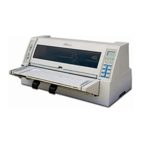
The Model 730-1 is an operationally simple, compact, microprocessor controlled,
dot-matrix, impact printer. The unit prints 7x7 dot matrix characters at 10
characters per inch in line lengths up to 8inches at arate of 100 characters
per second. The printer features three-way paper handling.
1. 9-1/2" (9" pin to pin) wide standard computer fanfold forms, with fixed
position pins to ensure pinfeed paper registration. The paper can be
multipart up to three parts.
2. Rolled paper, 3-1/2 to 8-1/2- wide, 1" core and up to 5" diameter. The
printer includes aroll paper holder. Abuilt-in rip-and-read cutting
edge allows easy removal of paper. The first line of following page is
printed within five lines of tear edge. Two ply paper may be used with
operator attendance.
3. Single sheets of 8-1/2 inch wide paper, hand fed as with an ordinary
typewriter.
The printer's character set consists of 96 US ASCII characters. Normal size
characters can be printed at up to 80 characters per line. Elongated characters
which are double-width characters can be printed at up to 40 characters per line
Other significant features include:
1. Reliable free-flight head.
2. Microprocessor technology.
3. Full line buffer.
4. Fast carriage return at 10" per second.
5. Special line feed buffer for host-controlled forms control.
6. Compact size (5"H x14-1/2"W x11 MD).
-1-

SPECIFICATIONS
Ribbon (12 per box)
Paper
Printing Speed
Characters Per Line
Print Width
Character Structure
Line Feed Buffer
Line Feed Repeat Rate
Vertical Spacing
Horizontal Spacing
Parallel Data Input Connector
Code
Character Set
Input Character Format
Input Data Rate
Input Voltage/Frequency
Power Requirements #
Size
Weight
20-yard zip pack mobius loop
(Centronics Part No. 63701468-6003)
Cut Sheets (8-1/2- wide)
Rolls (3-1/2" to 8-1/2" wide x5Hdiameter
with 1*' Core ),2ply
Fanfold (9 Wpin-to-pin), 3ply
28 lines per minute (1pm) at 80 characters
per line (cpl) or 74 1pm at 20 cpl left justified
80 maximum
8inches maximum (204 mm)
7x7 Dot Matrix
Capacity for 255 pending line feeds.
9line feeds/second
6lines per inch
10 characters per inch
40-pin PC edge connector
Standard US ASCII-2
96 US ASCII alpha-numeric character codes.
8parallel data bits.
Up to 9300 characters/second.
120 VAC +10% 60 Hz
100 watts
14-1/2-W x11"D x5"H? (368 mm) x(279 mm) x
(127 mm)
12 lbs. (5.4 Kg)
=2-

SETTING UP
INSPECTION
Visually inspect the printer for signs of damage received during shipment.
Notify the common carrier immediately of any discrepancies.
NOTE
Any attempt to operate adamaged
printer voids the warranty and may
cause further damage.
QUICK SET-UP PROCEDURES
1. Install roll paper holder and roll paper, fanfold paper, or single-sheet
paper.
2. Remove top cover and check ribbon, then reinstall cover and install top
paper guide. Ensure that head restraint and ribbon cover packing has been
removed. CAUTION
When turning power on or off, the
RESET ON/OFF switch should always
be placed in the ON position to
prevent erroneous communications be-
tween the host device and the printer
and to prevent damage to the printer.
3. Place POWER switch in the OFF position and place RESET ON/OFF switch
in ON position.
4. Connect power cord to a3-wire, grounded AC outlet.
5. Connect interface cable to printer interface connector.
6. Place POWER switch in ON position and observe that the LED illuminates
through paper exit slot.
7. Place RESET ON/OFF switch in OFF position to receive data.
Figure 1. MODEL 730-1 PRINTER
-3-

ROLL PAPER HOLDER INSTALLATION
1
.
Set the printer on aflat surface with enough room in back of the printer
for the roll paper holder.
2. Refer to Figure 2and squeeze the support arms together slightly.
3. Insert support arms into two holes provided at rear of printer and release
support arms.
4. Remove core hub from plain end and insert roller through standard 1-inch
paper roll core and place roll on holder as shown with paper feeding from
bottom of roll.
m\
SLIDE CORE ON AXLE
FOR PROPER ROLL
ALIGNMENT
£7
PLAIN END /
PUSH THIS PORTION OF HUBS
INTO CORE ENDS
TOP PAPER GUIDE PAPER
PAPER
ROLL
PAPER ROLL
HOLDER
PLATEN FACE
PAPER
GUIDE
ARM SUPPORT ARM
PAPER DRIVE
ROLLER
PRINTER
CABINET
(CUTAWAY)
Figure 2. ROLL PAPER HOLDER INSTALLATION
-4-

PAPER INSTALLATION
Printer Forms Selection Guide
The printer has the unique ability to handle three common types of paper;
cut sheet, roll, and fanfold. Line registration can vary depending on the
type of paper being used. To select the ideal type of paper or form for
your application, you should consider the following guidelines:
1. Precise registration, 6lines to the inch, can be best maintained by using
continuous fanfold edge-punched paper. This type of paper should be used
wherever registration is critical such as in preprinted forms applications.
2. The last line can be printed up to 1.6" (40.6 mm) from the bottom of the
page when using cut sheet paper.
3. In pinch-feed applications when using roll paper or cut-sheet paper, the
line spacing can vary depending upon the finish and weight of the paper.
Check the paper for your application before use or procurement of preprinted
forms.
Refer to the appropriate procedure to install roll paper, fanfold paper,
or single sheets/forms.
NOTE
When installing ribbon or paper,
always back print head away from
.5-

Roll Paper
1
.
Install the roll on the paper holder as described previously.
2. Remove top cover by lifting rear edge until latches are clear of main
cover and then slide cover back to disengage front clips.
3. Retract head to the paper/ribbon load position by rotating head release
lever fully counterclockwise.
4. Push the pinch-roller release lever towards rear of printer.
5. Feed the paper over the paper guide arm and through the bottom rear of the
printer under the paper drive roller.
6. Align the edges of the free end of paper with paper-drive roller edges and
straighten as required.
7. Remove any skew between paper roll and the paper-drive roller by sliding
the roll on the holder axle to align the paper as shown in Figure 3.
THUMB WHEELS
ALIGN ROLL PAPER WITH
"THIS DIMENSION
Figure 3. PAPER DRIVE ROLLER
8. Push the pinch-roller release lever forward to secure paper.
9. Advance paper into printer by turning either thumbwheel until paper exits
through the top of the printer.
10. Check ribbon position, remove slack if necessary, move head-release lever
to print position, and install top cover. Print position numbers on print
head assembly indicate head-release lever positions for number of plies of
paper as ageneral rule. Note that print-head position may vary depending
upon type of paper being used.
-6-

Fanfold Paper
1. Remove the top cover, retract head and make sure release lever is in down
position (open).
2. Engage paper onto pins of paper-drive roller at bottom rear of printer.
3. Hold paper in place while turning either thumbwheel until the paper exits
through the top of the printer.
4. Be sure the paper supply is feeding properly.
5. Check ribbon position, remove slack if necessary; move head-release lever
to appropriate print position and install top cover. Print position
numbers on print head assembly indicate head release lever positions for
number of plies of paper as ageneral rule. Note that the print-head
position may vary depending upon type of paper being used.
NOTE
When using pinfeed type paper, the
pinch roller release lever should
be left in the down position (away
from printer). This provides more
positive drive by the feed pins
and prevents imprinting on second and
third copies of multipart paper caused
by pressure of the paper-drive roller
rings on the carbon paper between the
copies.
Single Sheets/Forms
1. Push pinch-roller release lever towards rear to the open position.
2. Insert top edge of sheet/form through opening in the rear of the printer
under the paper drive roller.
3. Slide sheet/form into rear of printer under paper-drive roller until
sheet/form rises through paper-exit slot.
4. Match up top and bottom edges of paper. Straighten paper as required.
5. Pull pinch-roller release lever forward to closed position.
6. Manually turn two thumbwheels until sheet is in position for the first
printed line.
-7-

RIBBON INSTALLATION
Zip-Pack ribbons are used with the printer. The procedure for installing the
ribbon is as follows:
1. Remove printer top cover to gain access to ribbon tray.
NOTE
Use the throwaway plastic gloves
provided with the new ribbon when
performing the following steps.
2. Retract the head by rotating the head-release lever fully counterclockwise.
3. Refer to Figure 4and push the driven roller away from the drive roller
and unthread the old ribbon and discard it.
4. Remove the Zip-Pack from the plastic bag.
5. Place Zip-Pack in printer tray as shown in Figure 5.
6. Pull ribbon out from both ends of Zip-Pack and thread according to ribbon
threading diagram, being careful to position mobius loop twist on the left
side (See Figure 4).
7. Hold ribbon in place by pressing down on plastic strip through hole in
shell piece and then remove wrapper by pulling end of wrapper.
8. Remove and discard shell and plastic strip.
9. Manually advance drive roller clockwise until slack is removed from
ribbon
.
10. Engage head and install top cover.
RIBBON SPECIFICATIONS
The printer uses a180° mobius loop ribbon configuration that allows printing
on upper and lower portions of the ribbon on alternate passes, thereby increasing
ribbon life. The specifications are as follows:
LENGTH: 20 yards (18.3 meters)
WIDTH: 9/16 inch +1/64 inch (14.3 mm +0.4 mm)
THICKNESS: 0.0004 inch +0.00025 inch (0.01 mm +0.0064 mm)
Ribbons may be obtained from Centronics in packages of one dozen. The part
number for apackage is 63701648-6003. The ribbon color is black.
_o

PAPER/RIBBON
LOAD POSITION
DRIVE ROLLER
(MANUALLY ADVANCE CW
ONLY TO REMOVE SLACK) ZIP PACK
RIBBON
RIBBON TENSIONER
OPEN ARM TO THREAD
RIBBON. INSURE THAT
RIBBON IS DOWN ALL
THE WAY. THEN
RELEASE ARM
Figure 4. RIBBON THREADING DIAGRAM
SHELL
Figure 5. ZIP-PACK INSTALLATION DIAGRAM
_9_

OPERATION
USING THE PRINTER
1
.
Be sure that aribbon is installed in the printer and an adequate supply
of paper has been installed.
2. Place RESET ON/OFF switch in the ON position. (Refer to Figure 6.) This
prevents the printer from printing and keeps it "off-line".
CAUTION
When turning power on or off, the
RESET ON/OFF switch should always
be placed in the ON position to
prevent erroneous communications be-
tween the host device and the printer
and to prevent damage to the printer.
3. Place POWER ON/OFF switch in ON position. "Power On" LED should be
visible through paper-exit slot.
4. Place RESET ON/OFF switch in the OFF position. Printer is ready to
accept data.
5. To turn printer off, place RESET ON/OFF switch in ON position. Then,
place POWER ON/OFF switch in OFF position.
HINTS AND TIPS
•Always plug printer into a3-wire grounded outlet.
•Do not leave or place objects on any part of printer.
•Do not subject printer to temperatures below +40°F (4°C) during operation,
to asudden change in temperature, to dust, or to extreme shock.
•Use only adry, soft cloth to clean printer surfaces. Do not use harsh
detergents or chemicals.
•Avoid touching print-head print wires when handling paper or changing
ribbons
•
•Periodically clean ink build-up from ribbon guide path and remove paper dust
from interior.
-10 -

00821
RED LED (Visible through paper exit
slot. Indicates power is ON ~+5 volts.]
RESET ON/OFF SWITCH
POWER SWITCH
FRONT
REMOVABLE TOP COVER
(Provides access to change
ribbon and load paper.)
POWER
CORD
PARALLEL INPUT
CONNECTOR
(40 pin edge connector)
PINCH ROLLER
RELEASE LEVER
(Used to load paper.)
REAR
Figure 6» OPERATOR CONTROLS

PRINCIPLES OF OPERATION
All logic, control, drive, and power supply circuits are contained on one
printed circuit board within the printer (Figure 10). The print head is
mounted on acarriage assembly driven by aDC motor. Printing is performed in
the forward direction only (left to right), printing up to seven dots per
column. The paper drive roller is driven by aline feed solenoid which
advances paper one line (1/6 inch) each time the line feed solenoid is
actuated. The ribbon drive motor (AC) moves ribbon past the print head at all
times except when the carriage assembly actuates the sensor at the leftmost
carriage position. The power supply provides +5V regulated, +5V EXT SENSE for
host device sense, +12V regulated for motor drive, +17 for solenoid drive,
and +24 VAC for the ribbon drive motor.
The host device transmits 8-bit parallel (US ASCII) data signals and adata
strobe signal to the printer logic. Control of the transfer of data is
achieved using the busy, demand, and acknowledge signals generated by the
printer logic. 00819
PRINTED CIRCUIT BOARD IPRINTER «
•MECHANICS I
HOST
DEVICE
8-BIT DATA
IDATA STROBE
BUSY
DEMAND
ACKNOWLEDGE
•CPU
•MEMORY
•CONTROL
LOGIC
•DRIVE
CIRCUITS
+5V EXT SENSE I
SOLENOID DRIVE
FWD/REV
7-PIN
PRINT
HEAD
CARRIAGE
DRIVE
MOTOR
(DC)
LINE FEED LINE
FEED
SOLENOID
+5V
POWER
SUPPLY
24 VAC »- RIBBON
DRIVE
MOTOR
(AC)
I
Figure 7. 730-1 PRINTER BASIC BLOCK DIAGRAM
The printer accepts and stores input character data in an 80-character holding
buffer until either the buffer is filled or acarriage return (CR) control
code is received. If the buffer is filled or aCR code is received, the
content of the holding buffer is printed. Printing of the characters is
achieved by energizing solenoids in the print head which drive circular pins
against the ribbon, paper, and platen as the print head is moved by the
carriage drive motor forming the characters in a7x7 dot-matrix pattern. Upon
completion of printing the print head is moved to the left margin and the
paper is advanced one line by energizing the line feed solenoid.
-12-

Line feed (LF) control codes received by the printer control paper movement.
Each line feed code received causes the paper to be advanced one line. The
printer has aspecial line feed buffer, separate from the holding buffer,
which can store up to 255 line feed commands. LF control codes are received
at the same data transfer rate as character data (up to 9300 characters per
second). The initial LF code causes an immediate advance of one line.
Additional line feed codes received are stored as acount in the line feed
buffer. Line feed codes and character data sent to the priinter may be
intermixed, however, all line feeds received are performed before printing the
next line of data.
Automatic line feed upon completion of printing each line may be disabled by
removing resistor R34 on the printer logic printer circuit board. If this
function is disabled, the first line of data will be printed when aCR control
code is received or abuffer full condition occurs. After printing the first
line of data, the print head is returned to the left margin and the paper is
not advanced. The second line (and subsequent lines) of data must have at
least one LF control code preceed each CR control code or buffer full condition,
or overprinting will occur.
Line feed codes may be used for limited paper handling functions. Each line
feed code moves the paper one-sixth of an inch. Thus, for example, if it is
desired to move the paper 12 inches, 72 line feed codes are required before a
CR control code is sent.
Elongated characters can be printed which are double width characters formed
by printing each column of dots within each character twice. Spaces between
characters are also twice as wide. This effectively halves the number of
characters per inch (cpi) from 10 cpi to 5cpi. Figure 8shows the normal
and elongated character styles.
Elongated characters are initiated by using the escape code ESC, SO code
sequence (or data bit 8logically high) and terminated by the escape code ESC,
SI code sequence (or data bit 8logically low). Elongated characters are
automatically terminated at the end of aline. Reception of an ESC SO code
sequence causes all data following the code sequence to be printed elongated.
Control code sequence ESC, SI causes all data following the code sequence to
be printed normal size. Elongated characters may be initiated and terminated
any number of times within aline. The end of aprint line terminates
printing of elongated characters, and unless elongated characters are initiated
by the ESC, SO code sequence preceeding the data for the next line, the
characters in the next line will be printed normal size.
-13-

!t*X&1
()X + t-/
1234567
89•*
ts>?
ABCDEFG
HI J KLMN
PQRSTUUW
XYZC\3tf
*3b c defG
hiJ k 1mn
u
NORMAL CHARACTERS
1II *iu %^i
<>>K .+. *—/
o:l 22 3*+ l^* A^
Q<? A
r..•* -:: .!•• *?
(>? AKit Ci:> e: F-\j»
I--I xU K i... MNCD
RaR3*r UVW
XVif: i:: \::i t> <-•
^Hi fc> en- cl frek •r C3
hl :i. *.j KXITl r*i CD
ys> c:* T* <» •b i..I vUl
*•* *rf 'J3Z •<: 1>•* tt
ELONGATED CHARACTERS
Figure 8. 730-1 PRINTER CHARACTER STYLES
-14-

Figure 9shows the printer interface timing. Eachset of data bits (1-8)
sent to the printer is strobed by the DATA STROBE signal sent to the printer
by the host device. Within 50 nsec following the trailing edge of the DATA
STROBE signal aBUSY signal is generated by the printer which is sent to the
host device. The BUSY signal informs the host device that the printer is
processing the input data and that no additional data from the host device
will be accepted by the printer. After completion of processing the input
data an acknowledge (ACK) signal is sent to the host device indicating that
the data sent by the host device has been accepted and processed. Within 50
nsec following the leading edge of the ACK signal the BUSY signal is terminated
indicating that the printer is again ready to accept additional input data. A
DEMAND signal is also generated by the printer and is available to the host
device. The DEMAND signal is the inverse of the BUSY signal and when present
(positive) indicates that the printer is not busy and is ready to accept
data.
MTA "™ Jis+aH-Jsfc
DATA STROBE
**
\h
•as--"
ACK
BUSY
-th
-!V
J^t-i-t^"
Hi
S5T-- h-
Hp^
DEMAND lb
•100 usee is for data reception and line feeds that
do not fill tha line feed buffer. For line feeds that
is 110 msec +10%. -0%.
the maximum time i
Figure 9. INTERFACE TIMING
The time between the trailing edge of the DATA STROBE signal and the leading
edge of the ACK signal (data transfer cycle time) varies with the functions to
be performed by the printer. For normal data inputs and LF control codes
which do not fill the line feed buffer, the duration is nominally 160 usee.
For LF control codes which fill the line feed buffer, the maximum time is 110
msec +10, -0%. The maximum time for carriage return codes is 2.6 seconds. In
approximately 10% of the normal data transfer cycles amicroprocessor interrupt
occurs which extends the time from anonimal 100 usee to approximately 200 usee.
Figure 10 shows the acknowledge timing on power-up. When power is initially
turned on, approximately 20 msec is required for internal voltages (+5V) to
stabilize. Within 30 msec after power is turned on the BUSY signal is generated
and the printer remains in the BUSY condition for the next 170 msec. The BUSY
signal is then terminated and the printer generates the first acknowledge
pulse indicating that the printer is no longer BUSY, is on line, and is ready
to accept data. Data should not be sent to the printer until the first ACK
signal is sent to the host device.
-15-

POWER ON
SWITCH
5V LINE
BUSY LINE
ON
OFF
+5V
OV
+5V
OV
ACKNLG
20MS H
-30MS-
200MS
-30MS-
WVWWA indeterm.nate
W/M////M COND.T.ON
1ST ACKNLG PULSE
(PRINTER ON LINE)
Figure 10. ACKNOWLEDGE TIMING ON POWER-UP
The Power ON/OFF switch controls the application of primary power to the
printer. When power is turned on, an LED visible through the paper exit slot
indicates that the +5 volts is active. The RESET ON/OFF switch controls the
printer modes of operation. When placed in the ON position, the printer is
placed in alocal mode of operation, aBUSY signal is sent to the host device,
the printer electronics are reset, and the print buffer is cleared. When
placed in the OFF position, the printer electronics are reset, the print head
is returned to the left margin, and the BUSY signal is discontinued allowing
data to be sent by the host device. If the switch is placed in the ON position
when the printer is processing aline of data, the printer will complete
printing the line of data, return the print head to the left margin, then
reset the printer electronics and clear the print buffer. If the printer is
performing multiple line feeds at the time when the switch is placed in the ON
position, the line feed operation currently being performed will be completed
and the remaining line feeds will be processed when the printer is returned to
the on-line mode. The RESET ON/OFF switch should be placed in the ON position
when turning power to the printer on or off as extraneous acknowledge (ACK)
signals can occur during the periods when power is initially turned on or
off. CAUTION
Actuation of the On Line/Off Line switch
results in loss of data contained in the
print buffer.
16-
Other Centronics Printer manuals
Centronics
Centronics 352 User manual
Centronics
Centronics 306 User manual
Centronics
Centronics 101 User manual
Centronics
Centronics 101 User manual

Centronics
Centronics 702 User manual
Centronics
Centronics 101AL Guide

Centronics
Centronics 101AL User manual
Centronics
Centronics 101A User manual

Centronics
Centronics 705 User manual

Centronics
Centronics 101A User manual
