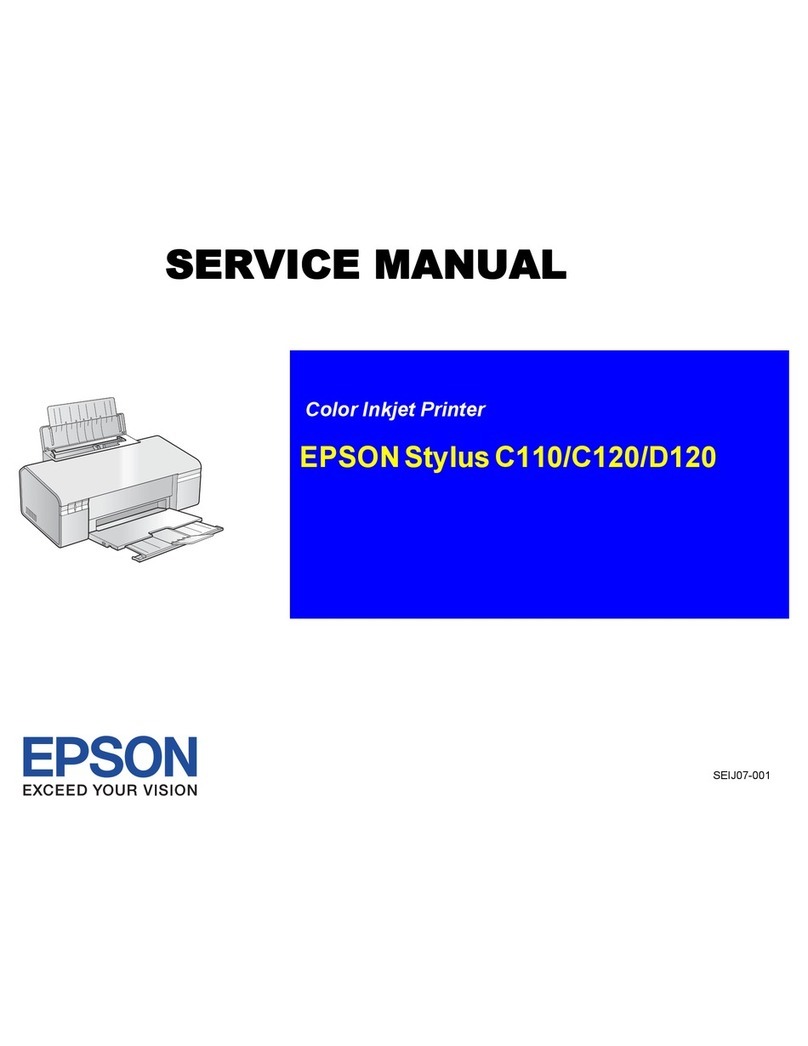
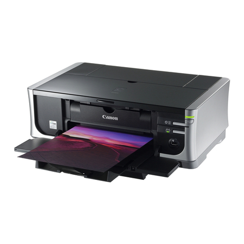
Centronics 352 User manual

C:EnTRDnlC:S
CEnTRDnlC:S
· cFr
-~s
TP
780
MODEL
352
·
c:
I .
PRINTER
: s
37403520
REV
A MAY
1982
·C:E1111-c.u1
llLS
C:EnTRDnlCS
C:EnTRDnlC:S
c:
E
nTRD
n I
c:
s
TECHNICAL MANUAL

THE INFORMATION CONTAINED HEREIN IS
PROPRIETARY AND
IS
NOT TO
BE
RELEASED
OR
REPRODUCED WITHOUT WRITTEN PERMIS·
SION
OF
CENTRONICS DATA COMPUTER CORP.
SERVICING INFORMATION FOR YOUR PRINTER MAY
BE
OBTAINED BY CALLING THE NUMBERS LISTED BELOW.
(ASK FOR FIELD ENGINEERING)
C:EnTRDnlC:S®
data computer corporation
Hudson, New Hampshire 03051
Tel. (603) 883-0111, TWX. (710) 228·6565, TLX. 94-3404
Field Engineering Headquarters (603) 883-0111
Regional Sales Offices
Northern Region (Mass.):
Mid-Atlantic Region
(NJ):
Southern Region (Texas):
Western Region (Calif.):
Northwest Region (Calif.):
Tel.
(617)
935-6150,
TWX.
710-348-0343
Tel.
(609)
234-8266,
TWX.
710-897-1975
Tel.
(817)
461-5711,
TWX.
910-890-4916
Tel.
(714)
979-6650,
TWX.
910-595-1925
Tel.
(408)
744-1244,
TWX.
910-339-9324
District
Field Engineering Offices
New England
District:
Tel.
(617)
935-8130
New York
District
: Tel.
(516)
496-3506
Mid-Atlantic District: Tel.
(609)
234-8194
Midwest District: Tel.
(312)
956-6141
Southern District: Tel.
(817)
461-7121
Southwest District: Tel.
(714)
957-1510
Northwest District: Tel.
(408)
745-7040
International Offices
Centronics Data Computer (Canada) Ltd.
Mississauga, Ontario
Tel.
(416)
625-0770, TWX. 610-492-4382
Centronics Data Computer
(UK)
Ltd.
Burgess Hill, Sussex, England
Tel. 04446-45011, TLX.
877801
Centronics Data Computer (France)
71-73
Rue
Desnouettes, 75015 Paris, France
Tel. 828-4051, TLX. 202686
Centronics Data Computer (Germany), Gmbh
6000 Frankfurt am Main
71
Tel. 666-1021, TLX. 841-413224
Centronics
of
Puerto Rico
Dorado, Puerto Rico
Tel.
(809)
796-1881, TLX. 385-9349
©Copyright
1982
Centronics Data Computer Corp.
Centronics (Italia) S.P.A.
Via Santa Valeria
5,
20123 Milan, Italy
Tel. 809-516
Al
I rights reserved
Patents pending in U.S.A. and other countries
Printed in U.S.A.
Specifications subject
to
change
without
notice
3/82
Rev.
F

MODEL
352
PRINTER
37403520 REV A MAY1982
TECHNICAL
MANUAL


TABLE
OF
CONTENTS
Section
1• 1
1.
2
1.
3
1.
4
1.5
1.
6
2.
1
2.2
2.3
2.4
2.5
SECTION
1
GENERAL
INFORMATION
SCOPE
OF
THIS
MANUAL
•
•••••••••••••••••••••••••••••••••••••••
GENERA.L
DESCRIPTION•
••••••••••••••••••••••••••••••••••••••••
PHYSICAL
DESCRIPTION••••••••••••••••••••••••••••••••••••••••
1.
3.
1
1.
3.
2
1.3.3
1.3.4
Printing
Mechanism
.........•.........................
Paper
Handling
Mechanism
•••••••••••••••••••••••••••••
Electronic·s
.
........................................
.
Power
Supply
•••••••••••••.•••••••••••••••••••••••••••
PRINTER
OPERATION
•••••••••••••••••••••••••••••••••••••••••••
1.
4.
1
1.
4.
2
1.4.3
Character
Printing
...........................•.....•.
Paper
Mot
ion
•
•••••••••••••••••••••••••••••.
•
••••••••••
Special
Functions
•••••••••••••••••••
RELATED PUBLICATIONS•
•••••••••••••••••••••••••••••••••••••••
1.
5.
1
1.
5.
2
1.5.3
Unpacking/Repacking
Instructions
•••••••••••
Users
Manual
••••••••••••••••••.••••
Illustrated
Parts
Manual
•••••••••••
SPECIFICATIONS•
•••••.•••••••••••••••••••••••••••••••••••••••
SECTION
2
THEORY
OF
OPERATION
GENERA.L
•
••••••••••••••••••••••••••••••••••••••••••••
•
••••
• • •
BASIC
PRINTER
OPERATION•••••••••••••••••••••••••••••••••••••
FORMAT
CONTROLI.ER
•
••••••••••••••••••••••••••••••••••••••••••
2.3.1
2.3.2
2.3.3
2.3.4
2.3.5
2.3.6
Parallel
Interface
...••••••••••••..••••••••••••••••••
Serial
Interface
••••••••••••••••
8085
Microprocessor
.system
••••••
Character
Generator
•••••••••••••••••••••••••.•••••••••
Data
Buffer
•••••••
c-RAM.
••••••••••••••••••••••••••••••••••••••••••••••••
C-BUS
DATA
INTERFACE
CABLE••••••••••••••••••••••••••••••••••
PRINT
CONTROLLER••••••••••••••••••••••••••••••••••••••••••••
2.5.1
Data
Arguments
Definition
••••••••••••••••••••••••••••
-i-
1-1
1-2
1-2
1-3
1-3
1-3
1-3
1-4
1-4
1-5
1-5
1-5
1-5
1-6
1-6
1-6
2-1
2-1
2-7
2-7
2-9
2-10
2-10
2-10
2-11
2-11
2-13
2-13

TABLE
OF
CONTENTS
(cont'd)
Section
Page
2.6
2.7
2.8
2.9
3.1
~-2
3.3
3.4
3.5
3.6
2.5.2
2.5.3
2.5.4
2.5.5
2.5.6
2.5.7
2.5.8
2.5.9
2.5.10
2.5.11
2.5.12
2.5.13
2.5.14
2.5.15
2.5.16
Status
Bytes
•••••••••••••••••••••••••••••••••••••••••
Paper
Motion
Argument
Description
••••••••••••••••••••
Printer
Status
Byte
•••••
~
••••••••••••••••••••••••••••
Self-Test
Status
Byte
••••••••••••••••••••••••••••••••
Accumulated
Paper
Motion
Steps
•••••••••••••••••••••••
Pape·r
Motion
Steps
Remaining
After
Abort
•••••••••••••
Reverse
Paper
Motion
Before
Print
••••••••••••••••••••
Forward
Paper
Motion
Before
Print
••••••••••••••••••••
Pr
int
Colilmand
•
•••••••.•••.•••••••.•••••••••••••••••••
Reverse
Paper
Motion
After
Print
•••••••••••••••••••••
Forward
Paper
Motion"After
Print
•••••••••••••••••••••
Print
Density/Ty'pe
..................
. ,
...............
.
Matrix
Size
•............
•
...••.••••...•..•...........
I>c>t
Pitch
...•..........•.................•...........
Inter-character
Skip
................................
.
POSITIONAL
INFORMATION
AND.
USE
••••••••••••••••••••••••••••••
2.6.
1
2.6.2
Standard
Character
Placement
••••••••••.•••••••••••••••
Graphic
Mode
•
••••••••••••••••••••••••••••••••••••••••
CHARACTER
PATTERN
GENERATION
••••••••••••••••••••••••••••••••
2.7.1
2.7.2
2.7.3
2.7.4
Standard
7-Dot
Wide
Character
Generation
•••••••••••••
Non-Standard
with
Character
Generation
•••••••••••••••
Graphic
Mode
•
••••••••••••••••••••••••••••••••••••••••
High
Density
Pr
int
.
.................
!9
••••••••••••••••
STEPPER
DRIWR
•
•••••••••••••••••••••••••••••••••••••••••••••
CAR.RIAGE
SERVO
SYSTEM.. • • • • • • • • • • • • •
•••••••••••••••••••••••••
SECTION
3
MAINTENANCE
MA.INTENANCE
SUMMARY
•
••••••••••••••••••••••••••••••••••••••••
PRINTER
MARKING
AND
CONFIGURATION
•••••••••••••••
3.2.1
l.2-r2
3.
2.,3
Printer
Nameplate
.
..................................
.
Printed
-Circuit.
Boat'd
Marking.-
...
-.---····-···.+
...
._._.
..
...
Printer
Configuration
••••••••••••••
,
•••••••••••••••••
PREVENTIVE
MAINTENANCE
••••••••••••••••••••••••••••••••••••••
TROUBLESHOOTING
GUIDE
•••••••••••••••••••••••••••••••••••••••
ERROR
INDICATORS•
•••••••••••••••••••••••••••••••••••••••••••
SELF-TEST
•
•••••••••••••••••••••••••••••••••••••••••••••
•
••
• •
-ii-
2-14
2-15
2-15
2-16
2-17
2-17
2-17
2-17
2-18
2-18.
2-19
2-19
2-19
2-19
2-20
2-20
2-20
2-21
2-21
2-21
2-22
2-22
2-22
2-23
2-26
3-1
3-1
3-1
l.~1-
3-2
3-2
3-3
3-5
3-5

TABLE
OF
CONTENTS
(cont'd)
Section
~age
4.
1
4.2
4.3
4.4
4.5
4.6
4.7
4.8
5.1
5.2
5.3
5.4
5.5
5.6
5.7
5.8
5.9
SECTION
4
ADJUSTMENTS
ADJUSTMENT
StJMMARY
••••••••••••••••••••••••••••••••••••••••••
CARRIAGE
DRIVE•
•••••••••••••••••••••••••••••••••••••••••••••
CARRIAGE
DRI'VE
·
BELT
•••••••••••••••••••••••••••••••••••••••••
PAPER DRIVE BELT •
••••••••••.•••••••••••••••••••••••••••••••••
TRACTOR
GEAR
BACKLASH. • • • • • • • • • • • • • • • •
••••••••••••••••••••••
PAPER EMPTY SWITCH•
•••••••••••••••••••••••••••••••••••••••••
OPTICAL
SENSOR
AND
ENCODER/TIMING
DISC
••••••••••••••••••••••
HORIZONTAL
OFFSET
ADJUSTMENT
••••••••••••••••••••••••••••••••
REMOVAL/REPLACEMENT,
SECTION
5
REMOVAL/REPLACEMENT
RECOMMENDED
SPARES
•••
PAPER
RACK
OUTLET
ASSEMBLY
••••••••••••••••••••••••••••••••••
PAPER
RACK
INLET•
•••••••••••••••••••••••••••••••••••••••••••
COVER
ASSEMBLIES •
•••••••••••••••••••••••••••••••••••••••••••
CO'VER
INTERLOCK
MAGNET
•
•••••••••••••••••••••••••••••••••••••
RIBBON
CASSETTE
AND
GUIDE
•••••••••••••••••••••••••••••••••••
PRINT
HEAD
ASSEMBLY
•
••••••••••••••••••••••••••••••••••••••••
HEAD
FLEX
CABLE
••••••••••••••••••••••••••••••••••••••••••••
HEAD
ADAPTER
PCB• • • • • • • • • • • • • • • • • • • • • • • • • • • • • • • • • • •
••••••••
5.
10 PRINT
.MECHANISM
•
•••••••••••••••••••••••••••••••••••••••••••
5.
11
DUST
COVER
•
••••••••••••••••••••••••••••••••••••••••••••••••
5.
12
CARRIAGE
DRIVE
MOTOR
BELT
•••••••.•••••••••••••••••••••••••••
5.
13
CARRIAGE
DRIVE
BELT
•
•••••••••••••••••••••••••••••••••••••••
5.14
CARRIAGE
DRIVE
MOTOR
AND
RIBBON
DRIVE
MOTOR
MOUNTING
BRACKET
•
•••••••••••••••••••••••••••••••••••••••••••••••••••
-iii-
4-1
4-1
4-1
4-3
4-3
4-4
4-5
4-6
5-1
5-1
5-2
5-2
5-3
5-3
5-3
5-6
5-7
5-8
5-10
5-11
5-11
5-13

Section
5.15
OPI'IC
SENSOR
ASSEMBLY••••••••••••••••••••••••••••••••••••••
5.16
CARRIAG~
DRIVE
MOTOR•••••••••••••••••••••••••••••••••••••••
5.17
ENCODER/TIMING
DISC••••••••••••••••••••••••••••••••••••••••
5.18
RIBBON
DRIVE
MOTOR.••••••••••••••••••••••••••••••••••••••••
5.
19
COVER
INTERLOCK
SWITCH
••••••••••••••••••••••••••••
;
••••••••
5.20
PAPER
DRIVE
BELT•••••••••••••••••••••••••••••••••••••••••••
5 • 2 1 PAPER DRI'VE
MO'l'OR
•
••••
·
•••••••••••••••••••••••••••••••••••••
5.
22
TRACTOR
ASSEMBLIES,
LEFT/RIGHT
•••••••••••••••••••••••
-
••••••
5.
23
PAPER
EMPTY'
SWI'l'CH
•
••••••••••••••••••••••••••••••••••••••••
5.
24
POWER
SUPPLY ASSEMBLY
•••••••••••••••••••.•••••••••••••
•
•••••
5.25
FORMAT/CONTROLLER
CABLE••••••••••••••••••••••••••••••••••••
5.26
PRINT
CONTROLLER
PCB•••••••••••••••••••••••••••••••••••••••
5.
27
FORMAT
CONTROLLER
PCB
••••••••••••••••••••••••••••••••••••••
5.
28
PICO FUSE •
•••••••
._
•••••••••••••••••••••••••••••••••••••••••
5 • 29 ON/OFF
SWI
'!'CH
•
•••••••••••••••••••••••••••••••••••••••••••••
5.
30
MA.IN
FUSE•
•••••••••••••••••••••••••••••••••••••••••••••••••
5 • 31
POWER
CORD
•••••••••
_
••••••••••••••••••••••••••••••••••••••••
5.32
RECOMMENDED
SPARE
PARTS
LISTING••••••••••••••••••••••••••••
6.1
B.1
B.2
B.3
C.
l
SECTioN 6
FIELD
INSTALLABLE
OPTIONS/ACCESSORIES
PRINTER
OPTIONS/ACCESSORIES
••••••••••••••••••••••••••••••••
6.1.1
6.1.2
OPTIONS•
••••••••••••••••••••••••••••••••••••••••••••
ACCESSORIES
•••••••••••••••••••••••••••••••••••••••••
APPENDIX
A
ELEC'.PRICAL
DRAWINGS
APPENDIX
B
INTERFACE
INFORMATION
GENERA.L
INFORMATION
•
•••••••••••••••••••••••••••••••••••••••
PARALLEL
INTERFACE
CONNECTION
••••••••••••••••••••••••••••••
SERIAL
INTERFACE
CONNECTION
••••••••••••••••••••••••••••••••
APPENDIX
C
CONTROL
PANEL
SWITCHES
AND
INDICATORS
CONTROL
PANEL
SWITCHES
AND
INDICATORS••••••••••••••••••••••
-iv-
5-14
5-15
5-16
5-17
5-18'
5-19
5-20
5-21
5-22
5-23
5-24
5-25
5-27
5-26
5-28
5-29
5-29
5-30
6-1
6-1
6-1
B-1
B-1
B-3
C-1

Figure
1-1
1-2
1-4
2-1
2-2
2-3
2-4
2-5
2-6
2-7
).
3-1
3-2
3-3
3-4
3-5
3-6
3-7
4-1
4-2
4-3
4-4
4-5
4-6
4-7
4-8
4-9
5-1
5-2
5-3
5-4
5-5
5-6
5-7
5-8
5-9
5-10
5-11
5-12
5-13
5-14
5-15
5-16
5-17
LIST
OF
ILLUSTRATIONS
Model 352
Printer
..••••.••••••.•••••••••••••••••••.•••.••
Major
Assemblies
Model 352
•••••••••••••••••••••••••••••••
Character
Printing/Paper
Motion
••••••••••••••••••••••••••
Annual 352
Overall
Block
Diagram
•••••••••••••••••••••••••
Format
Controller
Bus
Structure
••••••••••••
~
•••••••••••••
Print
Controller
Bus
Structure
•••••••••••••••••••••••••••
Format
Controller
Block
Diagram
••••••••••••••••••••••••••
Parallel
Interface
Timing Diagram
••••••••••••••••••••••••
Stepper
Motor
Driver
••••••..•••••••••••••••••••••.•••••.•
Carriage
Drive
-Ribbon
Drive
••••••••••••••••••••••••••••
Printer
N~eplate
.•••••••••••••••.••••••••••••.••••••••.•
Printed
Circuit
Board
Marking
••••••••••••••••••••••••••••
Printer
Features
DIP
Switch
S3
•••••••••••••••••••••••••••
Printer
Features,
DIP
Switch
S1
••••••••••••••••••••••••••
Printer
Features,
DIP
Switch
S2
••••••••••••••••••••••••••
Printer
Features,
DIP
Switch
S4
••••••••••••••••••••••••••
Self-Test
Printout
•••••.•••••••••••..••••••••••••••••.•••
Carriage
Drive
Motor
Belt
Adjustment
•••••••••••••••••••••
Carriage
Drive
Belt
Adjustment
•••••••••••••••••••••••••••
Paper
Drive
Belt
Adjustment
••••••••••••••••••••••••••••••
· Tr
actor
Ge·ar
Backlash
Adjustment
•••••••••••••••••••••••••
Paper
Empty
Switch
Adjustment
••••••••••••••••••••••••••••
Mechanical
Adjustment
&
Optical
Sensor
and
Encoder/l'iming
Disc
.
...................
· . · · · · · · · · • · • · • • • • • •· · · · · · · · • ·
•·
· ·
Electrical
Adjustment,
Optic
Sensor
and
Encoder/Timing
Disc
..
..........................................
· · · · · · · · ·
Horizontal
Offset
Print
Sample
•••••••••••••••••••••••••••
Horizontal
Offset
Dip
Switch
•••••••••••••••••••••••••••••
Removal/Replacement
Paper
Rack
Outlet
Assembly,
Paper
Rack
Inlet,
Cover
Assemblies
and
Cover
Interlock
Magnet
••
Removal/Replacement,
Ribbon
Cassette
and
Guide,
Print
Head
Assembly
.
.••...•.•....•.••...•••..•..•.•••.•..
Removal/Replacement,
Head
Flex
Cable
•••••••••••••••••••••
Removal/Replacement,
Head
Adapter
:PCB
••••••••••••••••••••
Removal/Replacement,
Print
Mechanism
•••••••••••••••••••••
Removal/Replacement
Dust
Cover
•••••••••••••••••••••••••••
Removal/Replacement,
Carriage
Drive
Motor
Belt
Carriage
Drive
Belt
.
.............................................
.
Removal/Replacement;
Carriage
Drive
Motor
and
Ribbon
Drive
Motor Mounting
Bracket
•••••••••••••••••••••••••••••
Removal/Replacement,
Optic
Sensor
Assembly
•••••••••••••••
Removal/Replacement,
Carriage
Drive
Motor
••••••••••••••••
Removal/Replacement,
Encoder/Timing·
Disc
•••••••••••••••••
Removal/Replacement,
Ribbon
Drive
Motor
••••••••••••••••••
Removal/Replacement,
Cover
Interlock
Switch
••••••••••••••
Removal/Replacement,
Paper
Drive
Belt
••••••••••••••••••••
Removal/Replacement,
Paper
Drive
Motor
•••••••••••••••••••
Removal/Replacement,
Tractor
Assemblies
••••••••••••••••••
Removal/Replacement,
Paper
Empty
Switch
••••••••••••••••••
-v-
1-1
1-2
1-4
2-0
2-3
2-4
2-6
2-8
2-24
2-26
3-1
3-2
3-3
3-4
3-5
3-6
3-7
4-2
4-2
4-3
4-4
4-5
4-6
4-7
4-8
5-4
5-5
5-6
5-7
5-9
5-10
5-12
5-13
5-14
5-15
5-16
5-17
5-18
5-19
5-20
5-21
5-22

5
...
19
5-19
5-20
5-21
5-22
A-1
A-1
A-1
A-1
A-1
A-1
A-1
A-2
A-2
A-2
A-2
A-2
A-2
LIST
OF
ILLUSTRATIONS
(cont'd)
Removal/Replacement,
Power
Supply
Assembly, Format
Controller
Cable
•••••••••••..••••••••••••••••••••••••••••
5-25
Removal/Replacement
Pico.Fuse
••••••••••••••••••••••••••••
Removal/Replacement,
ON/OFF
Switch
•••••••••••••••••••••••
Removal/Replacement,
Main
Fuse
and Power Cord
••••••••••••
Removal/Replacement,
Cover
Latch
Springs
•••••••••••••••••
Schematic
Diagram,
Print
Controller
(64000160-9001)
5-26
5-28
5-29
5-29
(Sheet
1
of
7)
. . . . . . . . . . . . . . . . . . . . . . . . . . . . . . . . . . . . . . . . . . .
A-3
Schematic
Diagram,
Print
Controller
(64000160-9001)
(Sheet
2
of
7)
•••••••••••••••••••••••••••••••••••••••••••
A-4
Schematic
Diagram,
Print
Controller
(64000160-9001)
(Sheet
3
of
7)
........
-~
. . . . . . . . . . . . . . . . . . . . . . . . . . . . . . . . . .
A-5
Schematic
Diagram,
Print
Controller
(64000160-9001)
(Sheet
4
of
7)
•••••••••••••••••••••••••••••••••••••••••••
A-6
Schematic
Diagram,
Print
Controller
(64000160-9001)
(Sheet
5
of
7)
•••••••••••••••••••••••••••••••••••••••••••
A-7
Schematic
Diagram,
Print
Controller
(64000160-9001)
(Sheet
6
of
7) . . . . . . . . . . . . . . . . . . . . . . . . . . . • . . . . . . . . . . . . . . .
A~a
Schematic
Diagram,
Print
Controller
(64000160-9001)
(Sheet
7
of
7)
..•••.••••••...••..•••.•..••.
•....
• . • . • . . • . .
A-9/A-1
O
Schematic
Diagram,
Print
Controller
(64000564-9001)
(Sheet
1
of
·7)
•••••••••
~
• • • • • . • • • • • • • • • • • • • • • • • • • • • • • • • • •
A-11
Schematic
Diagram,
Print
Controller
(64000564-9001)
(Sheet
3
of
7)
•••••••••••••••••••••••••••••••••••••••••••
A-12
Schematic
Diagram,
Print
Controller
(64000564-9001)
(Sheet 3 of
7)...........................................
A-13
Schematic
Diagram,
Print
Controller
(64000564-9001)
(Sheet
4
of
_7)
• • • • . • . . • . . . • • . . . . . . . • . • . • • • • . . . • . . . . • . • . . .
A-14
Schematic
Diagram,
Print
Controller
{64000564-9001)
(Sheet
5
of
7)
••••••••••••••••••••
·•••••••••••••••••••••••
A-15
Schematic
Diagram,
Print
Controller
(64000564-9001)
(Sheet
6
of
7)
•••••••••••••••••••••••••••••••••••••••••••
A-16
A-2·
Schematic
Diagram,
Print
Controller
(64000564-9001)
A-3
A-3
A-3
A-3
A-3
A-3
A-4
A.-5
A-6
A-7
B-1
. B-2
C-1
(Sheet
7
of
7)
•••••••••••••••••••••
••••••••••••••••••••••
A-17/A-18
Schematic
Diagram,
Format
Controller
(63180247-9001)
(Sheet
1·of
6)...........................................
A-19
Schematic
Diagram, Format
Controller
(63180247-9001)
(Sheet
2
of
6)
•••••••••••••••••••••••••••••••••••••••••••
A-20
Schematic
Diagram, Format
Controller
(63180247-9001)
(Sheet
3
of
6)
••••••••••
·•·••••••••••••••••••••••••••••••••
A-21
Schematic
Diagram, Format
Controller
(63180247-9001)
(Sheet
4
of
·6)
........
• •
···•
...
•
.......
.-
•
......
• •
.--
..................
··
A-22
Schematic
Diagram, Format
Controller
(63180247-9001)
(Sheet
5
of
6) • • • • • • • • • • • • • • • • • • • • • • • • • •
•.
• • • • • • • • • • • • • • • •
A-23
Schematic
Diagram, Format
Controller
(63180247-9001)
(Sheet
6
of
6)
•••••••••••••••••••••••••••••••••••••••••••
Wiring
Diagram, Model 352
••••••••••••••••.••••••••••••••••
Assembly Diagram,
Print
Controller
(64000160-8001)
•••••••
Assembly Diagram,
Print
Controller
(64000564-8001)
•••••••
Assembly Diagram, Format
Controller
(63180247-8001)
••••••
Normal and Busy
Timing,
Parallel
Interface
•••••••••••••••
Parallel
and
Serial
Interface
Connectors
•••••••••••••••••
A-24
A-25/A-26
A-27
A-28
A-29/A-30
B-2
B-4
Control
Panel
Switches
and
Indicators
••••••.•••••••••••••
· C-1
-vi-

SECTION
1
GENERAL
INFORMATION
1•1
SCOPE
OF
THIS
MANUAL
This
technical
operation,
maintenance,
the
Model 352
printer.
who
maintain
electronic
manual
provides
detailed
information
on
the
theory
of
adjustment
and recommended
spare
parts
replacement
for
The manual
is
for
use
by
qualified
service
personnel
and
electro-mechanical
equipment.
1.2
GENERAL
DESCRIPTION
The Model 352
is
a
high
speed,
bidirectional,
impact
printer
that
uses
dot
matrix
techniques
for
character
generation.
The
printer
is
completely
self-contained,
composed
of
mechanical,
electro-mechanical
components and
printed
circuit
boards.
The
printed
circuit
boards
use
microprocessor
technology
to
minimize
components and
increase
reliability.
Maximum
throughput
is
achieved
with
bidirectional
printing
which
seeks
the
shortest
path
to
the
next
line
of
characters
when
printing
successive
lines
of
data.
Paper
is
moved
through
the
printer
by means
of
a
stepper
motor.
The Model 352
contains
many
features
to
help
perform
the
printing
job
more
easily
and
efficiently.
Some
of
the
more
significant
features
are:
o 200
CPS
Smart,
Bidirectional
Printing
o
Switch
Selectable
Lines
Per
Inch
o
Serial
or
Parallel
Input
Interfacing
o
Fanfold
Forms
or
Cut
Sheet
Forms Handlin•
o
Switch
Selectable
Forms
Length
o Pin·
Addressable
Graphics
o
Switch
Selectable
Characters
Per
Inch
o
Self-Test
Capability
Figure
1-1.
MODEL
352
PRINTER
1-1

Figure
1-2.
FORMS
RECEIVING
TRAY
LIES
MODEL
352
MAJOR
ASSEMB
1-2

The
printer
is
lightweight,
easy
to
install,
operate
and
maintain1
and
compatible
with
both
EIA
and
ANSI
standards.
In
addition
to
the
many
standard
features
built
into
the
Model
352,
there
are
many
options
and
accessories
that
may
be
added
to
provide
additional
capabilities.
1.3
PHYSICAL
DESCRIPTION
Physically
the
Model 352
is
compact and
lightweight.
The
printer
measures
22
inches
wide,
18
inches
deep
and
8
inches
high.
The
printer
weighs
40
lbs.
The
printer
covers
include
several
plastic
covers1
the
top
cover,
body
cover,
rear
cover
and
base
cover.
The body
cover
has
an
opening
in
the
lower
right
corner
for
the
control
panel.
There
are
four
major
assemblies
within
the
printer:
the
printing
mechanism,
paper
handling
mechanism,
electronics
and power
supply.
1.3.1
PRINTING
MECHANISM
The
printing
mechanism
consists
of
the
print
head
assembly,
carriage
assembly
and
carriage
drive
components.
The
carriage
drive
components
are
the
DC
drive
motor,
drive
belts,
pulleys,
encoder/timing
disc
and
optical
sensor.
These
components
drive
the
carriage
and
attached
print
head
back
and
forth
along
the
platen.
1.3.2
PAPER
HANDLING
MECHANISM
The
paper
handling
mechanism
is
capable
of
handling
either
fanfold
forms
or
cut
sheet
forms.
The mechanism
consists
of
a
stepper
motor,
pin
feed
tractors,
paper
guides
and
drive
rollers.
Fanfold
forms
are
moved
through
the
printer
using
the
pin
feed
tractors.
Cut
sheets
are
moved
through
the
printer
by
the
paper
drive
rollers.
The mechanism
handles
up
to
six
parts
using
either
form.
1.3.3
ELECTRONICS
The
printer
electronics
consists
of
two
printed
circuit
boards
{pcb)J
the
Print
Controller
pcb
and
the
Format
Controller
pcb.
The two
boards
are
located
under
the
printer
mechanism and
attach
to
the
bottom
cover.
The
Format
Controller
pcb
contains
the
control
panel
assembly
and
the
parallel
and
serial
input
connectors.
1.3.4
POWER
SUPPLY
The power
supply
is
located
in
the
left
front
of
the
printer
and
is
completely
enclosed.
The power
supply,
an
"off-line"
switching
type,
is
used
as
the
primary
power
source.
1-3

1.4
PRINTER
OPERATION
Basically,
all
printer
functions
can
be
grouped
into
one
of
three.
categories:
(1)
character
printing,
(2)
paper
motion,
and (3)
special
functions.
1.
4 . 1
CHARACTER
PRINTING
Once
the
data
has
been
received
and
formatted
by
the
Format
Controller,
characters
are
printed
by
selectively
activating
the
eight
print
wi~es
aligned
vertically
in
the
print
head.
A
ninth
wire
in
the
print
head,
under
micro-
processor
control,
provides
the
underlining
capability
in
the
printer.
The
print
commands
to
activate
the
print
wires
are
developed
by
the
Print
Controller
pcb
PROM's.
CARRIAGE
DRIVE
BELT
PAPER
FEED
MOTOR
Figure
1-3.
CHARACTER
PRINTING/PAPER
MOTION
1-4
20176
"')
·.

As
the
print
head
moves
across
the
paper,
the
appropriate
print
wires
are
momentarily
activated
driving
them
against
the
ribbon,
paper
and
platen
to
form
the
dot
matrix
character.
As
shown
in
Figure
1-3,
the
print
head
is
attached
to
the
carriage
assembly,
which
in
turn
is
attached
to
a
carriage
drive
belt.
The
carriage
is
driven
in
the
forward
or
reverse
direction
by
the
carriage
drive
motor which
rotates
the
belt
clockwise
(forward
direction)
or
counterclockwise
(reverse
direction)
•
1.
4.
2
PAPER
MOTION
Paper
is
moved by
pressing
the
paper
motion
switches1
line
feed
(LF)
paper
forward
(PAPER
FWD),
paper
reverse
(PAPER
REV)
or
form
feed
(FORM
FEED)
located
on
the
Format
Controller
pcb.
The
information
provided
by
the
Format
Controller
pcb
to
the
Print
Controller
pcb
establishes
the
direction
and
amount
of
paper
motion.
Physically,
paper
is
moved by
the
torque
from
the
paper
stepper
motor
which
is
applied
to
the
pin
feed
tractor
drive
gears
which
move
the
paper
up
or
down
as
shown
in
Figure
1-3.
1.4.3
SPECIAL
FUNCTIONS
As a
standard
feature,
the
printer
is
capable
of
printing
in
a
unidirectional
graphics
mode
or
bidirectional
graphics
mode. The
graphics
mode
is
selected
by
an
escape
sequence
and
the
graphics
program
is
completely
controlled
by
the
input
device.
Also
as
a
standard
feature,
the
printer
has
a
self-test
capability
which
is
activated
by
pressing
the
OVRD
TEST
switch
while
the
printer
is
deselected.
Test
data
is
continuously
printed
as
long
as
the
switch
is
pressed.
In
addition
to
the
printable
character
codes,
the
printer
also
recognizes
certain
special
control
codes
and
escape
sequences.
Refer
to
the
users
manual
for
a
list
of
the
codes
and
the
printer
action
performed
on
receiving
these
codes.
1.5
RELATED
PUBLICATIONS
The
following
publications
document
the
Model
352
printer
in
detail.
These
publications
are
available
through
the
Customer
Service
Department
at
Centronics.
1.
5.1
UNPACKING/REPACKING
INSTRUCTIONS
{P/N
37410005-9001)
The
unpacking/repacking
instructions
are
attached
to
the
outside
of
the
shipping
container
and
provide
the
necessary
information
to
unpack
or
repack
the
printer.
1-5

1.5.2
USERS
MANUAL
(P/N 37403521-9001)
The
users
manual
provides
a
general
description
of
the
printer
and
information
necessary
to
install,
program,
operate,
and
maintain
the
printer
on
a
users
level.
This
information
includes
set-up
procedures,
operating
instruc-
tions
and programming
instructions.
1.5.3
ILLUSTRATED
PARTS
MANUAL
(P/N 37403502-9001)
The
illustrated
parts
manual
contains
illustrations
and
lists
of
materials
detailing
all
assemblies
and
sub-assemblies
down
to
a
piece
part
level.
The manual
also
contains
a
numerical
index,
listing
every
part
in
numerical
order
and
referencing
the
part
to
a
figure
and an
index
number.
1.6
SPECIFICATIONS
SERIAL
INPUT
Interface
••••••.•••••••.•••....•..•...
RS-232C
Data
Format
••••••••••••••••••••••••••••
1
START
bit,
7
or
8
DATA
bits,
1
PARITY
bit,
and 1
or
2
STOP
bits
Input
Code
•••••••••••••••••••••••••••••
96
character
ASCII
Buffer
•••••••••••••••••••••••••••••••••
4K
character
buffer
PARALLEL
INPUT
Data
Format
••••••••••••••••••••••••••••
7/8
bit
ASCII
parallel
Input
Code
•••••••••••••••••••••••••••••
96
character
ASCII
Buffer
•••••••••••••••••••••••••••••••••
One
line
character
buffer
Input
Gating
•••••••••••••••••••••••••••
Data
Strobe
is
gated
with
Acknowledge
of
previous
character
PRINTING
Printing
Method
••••••••••••••••••••••••
Impact,
dot
matrix,
bidirectional,
logic
seeking
Dot
Matrix
•••••••••••••••••••••••••••••
7
dots
wide by 8
dots
high~
9th
wire
underline
Print
Speed
•••••••••••••••••••••
~······
200
characters
per
second
Country
Character
Sets
•••••••••••••••••
DIP
switch
selectable
for
U.S.A.,
Great
Britain,
Sweden/Finland,
Norway/
Denmark, Germany,
Italy,
France
and
Spain
1-6

Horizontal
Pitch
•••••••••••••••••••••••
Programmable
for
5,
6,
6.6,
7.5,
8.25,
10,
12,
13.2,
15
and
16.5
characters
per
inch
Maximum
Line
Length
(varies
with
horizontal
pitch)
5
cpi.
••••
66
columns
6
cp
i •
••••.••••••••••••••••••••••••••
79
columns
6.6
cpi
.............................
. 87
columns
7.
5
cp
i .
............................
. 99
columns
8.
25
cp
i .
.......
··
...................
. 109
columns
10
cpi
....
..........................
. 132
columns
12
cpi
.
.............................
. 158
columns
13.2
cpi
............................
. 174
columns
15
cp
i
..............................
. 198 columns
1
6.
5
cp
i .
...........................
. 218
columns
PAPER
HANDLING
Vertical
Pitch
•••••••••••••••••••••••••
6
or
8
lines
per
inch,
switch
selectable
Vertical
Slew
Speed
••••••••••••••••••••
8
inches
per
second
Forms
Length
•
••••••••••••••••••••••.•••
to
192
lines
Paper
Movement
•••••••••••••••••••••••••
Bidirectional
PAPER
REQUIREMENTS
Fanfold
Forms
Width
3.0
to
15.0
inches
Copies
...............................
Up
to
six
parts
Cut
Sheet
Width
•••••••
Copies
..............................
.
4.0
to
12.0
inches
six
parts
(76
to
381
mm)
(
101
to
304.8mm)
Up
to
NOTE:
refer
For
detailed
paper
specifications,
to
the
Model 352
Users
Manual
1-7

PHYSICAL/ENVIRONMENTAL
Height
•••••••••••••••••••••••••••••••••
7.5
inches
(190.5mm)
Depth
••••••••••••••••••••••••••••••••••
18.25
inches
(463.5mm)
Width.
• • • • • • • • • • • • • • •• •• • • • • • • • • • • •• • • •
22.
5
inches
(5
71
•
5mm)
Weight
•••••••••••••••••••••••••••••••••
40
lbs.
(88 kg)
Temperature
••••••••••••••••••..•••..•••
Operating:
500
to
104op c100
to
4ooc)
-400
to
151op
(-400
to
66oc)
Storage:
Humidity
•••••••••••••••••••••••••••••••
Operating:
10%
to
90%
(no
condensation)
Storage:
10%
to
95%
(no
condensation)
Power
Switcher
Power
Supply
••••••••••••••••
98
VAC
to
125
VAC
or
195
VAC
to
246
VAC
47
to
63
Hz
Input
Current
••••••••••••••••••••••••
4A
max.
at
110
VAC
2A
max.
at
220
VAC
1-8

IV
I
0
INPUT
DEVICE
PARALLEL
DATA
INPUT
')
SERIAL
DATA
INPUT
...
POWER
SUPPLY
(+12V.
-12V.
+5V.
+35VI
(INTERFACE
CABLE)
~
CONTROL
ADDRESS
BUS
(AD-A
12)
>
PANEL
--------
FORMAT
K'"
DATA
BUS
(DD-D71
"'\
PRINT
,/
CONTROLLER
CONTROLLER
v-
--
...._
RESET
-
HOLD
IT
•
FORMATTED
•DATA
INPUT
GOTIT
DATA
1/0
--
•DATA
""'-
CG
SEL
•
PRINT
FORMAT
--
COMMAND
.._
CR
SEL
....-
•
CHARACTER
WRITE
•
CARRIAGE
GENERATOR
MOVEMENT
-
•
PAPER
PWR
FAIL
~
MOVEMENT
,.
GNDS
,
+
~
,
VIDEO
SYSTEM
'
POWER
FAIL
OPTICAL
ENCODER
Figure
2-1.
MODEL
':::.
j OVERALL
BLOCK
DIAGRAM
20178-A
PINFIRE
DRIVE
-,/
PRINT
HEAD
~
CARRIAGE
CARRIAGE
MTR
DRIVE
.,/1
MOTOR
-"-
RIBBON
RIBBON
MTR
DRIVE
v
MOTOR
PAPER
STEPPER
MTR
DRIVE
/
STEPPER
MOTOR

2.1
GENERAL
SECTION
2
THEORY
OF
OPERATION
This
section
describes
the
operation
of
Model 352
printer
at
the
functional
block
level
and
includes
the
active
components
within
the
functional
block.
Refer
to
Figure
2-1.
The
electronic
control
circuits
for
the
printer
are
primarily
divided
onto
two
p.c.
boards:
the
Format
Controller
and
the
Print
Controller.
The
Format
Controller
accepts
either
serial
or
parallel
input
data
from
the
"host"
system,
serves
as
an
interface
to
the
Print
Controller,
and
determines
the
operational
functions
for
the
printers.
Also,
the
Format
Controller
contains
the
operator
accessible
controls
and
indicators.
These
controls
set-up
the
various
printer
functions
via
the
Format
Controller
circuitry.
The
Print
Controller
controls
paper
motion
and
printing
in
the
mechanism.
2.2
BASIC
PRINTER
OPERATION
The
Format
Controller
supplies
the
operating
parameters
to
the
Print
Controller
based
on
data
received
from
the
host
device
and
the
control
panel.
These
parameters
are
written
into
a
shared
Communication
Random
Access
Memory
(C-RAM)
on
the
Format
Controller.
The
parameters
are
written
according
to
an
address
format,
which
is
basically
divided
into
two
sections.
the
first
section
is
the
Control
Block
and
occupies
memory
locations
00
16
through
OF16·
This
part
of
the
memory
is
also
referred
to
as
the
print
buffer.
The
second
section
is
referred
to
as
the
Data
Block.
The
Control
Block
is
dedicated
to
transferring
a
print
command
and
paper
motion
arguments
from
the
Format
Controller
to
the
Print
Controller
and
transferring
status
information
concerning
printer
action,
paper
motion
and
self-test
results
from
the
Print
Controller
to
the
Format
Controller.
The
Data
Block
is
dedicated
to
transferring
information
on
printable
data
from
the
Format
Controller
to
the
Print
Controller.
A
detailed
description
of
these
parameters,
their
bit
structure,
and
input
timing
is
found
starting
with
Paragraph
2.5.3
in
the
Paper
Motion
Argument
Description.
In
order
to
discuss
how
data
is
processed
in
the
printer,
refer
to
Figure
2-2,
Format
Controller
Bus
Structure
and
Figure
2-3
Print
Controller
Bus
Structure,
and
assume
that
the
printer
has
just
been
turned
on.
Turning
the
printer
on
causes
the
microprocessor
to
go
through
an
initialization
routine
to
set
up
its
electronics
and
perform
the
following
functions:
o
Raise
the
GOT
IT
line.
The
Address
Bus (A0-A7)
and
the
Data
Bus
(DO-D7)
are
isolated
from
the
buffered
data
bus
(DB0-DB7).
Signal
information
is
conveyed
to
the
Format
Controller
that
data
cannot
be
transferred.
o Lower
WR
line
from
the
microprocessor.
This
line
controls
the
chip
enable
and
read/write
function
of
C-RAM.
o
Move
the
print
head
to
the
extreme
left
margin,
if
not
already
there.
2-1
Table of contents
Other Centronics Printer manuals
Centronics
Centronics 101AL User manual
Centronics
Centronics 101A User manual
Centronics
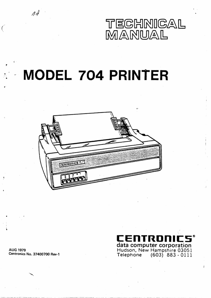
Centronics 704 User manual
Centronics
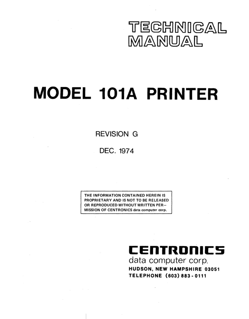
Centronics 101A User manual
Centronics
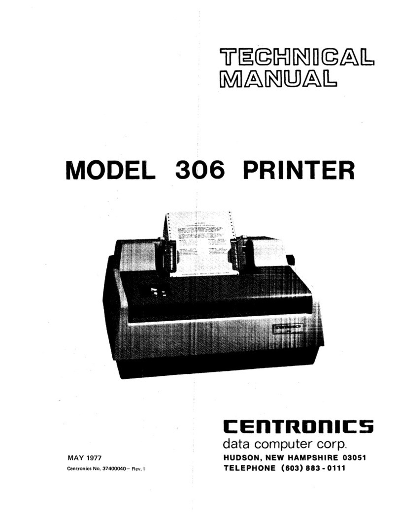
Centronics 306 User manual

Centronics
Centronics 101AL Guide
Centronics
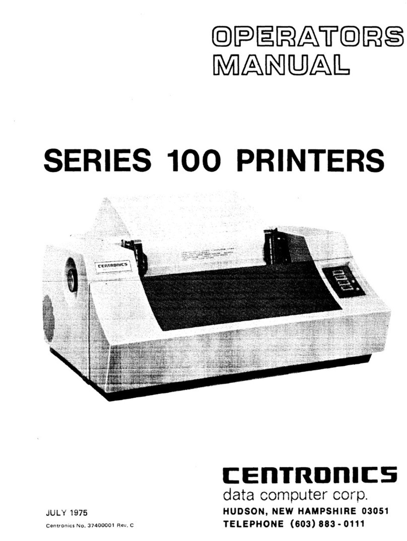
Centronics 101 User manual

Centronics
Centronics 702 User manual

Centronics
Centronics 101A User manual
Centronics
Centronics 730-1 User manual
