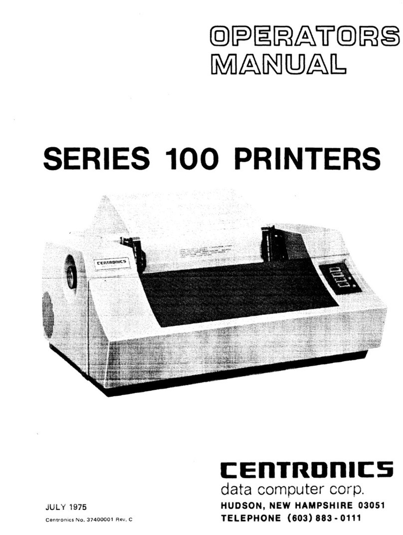
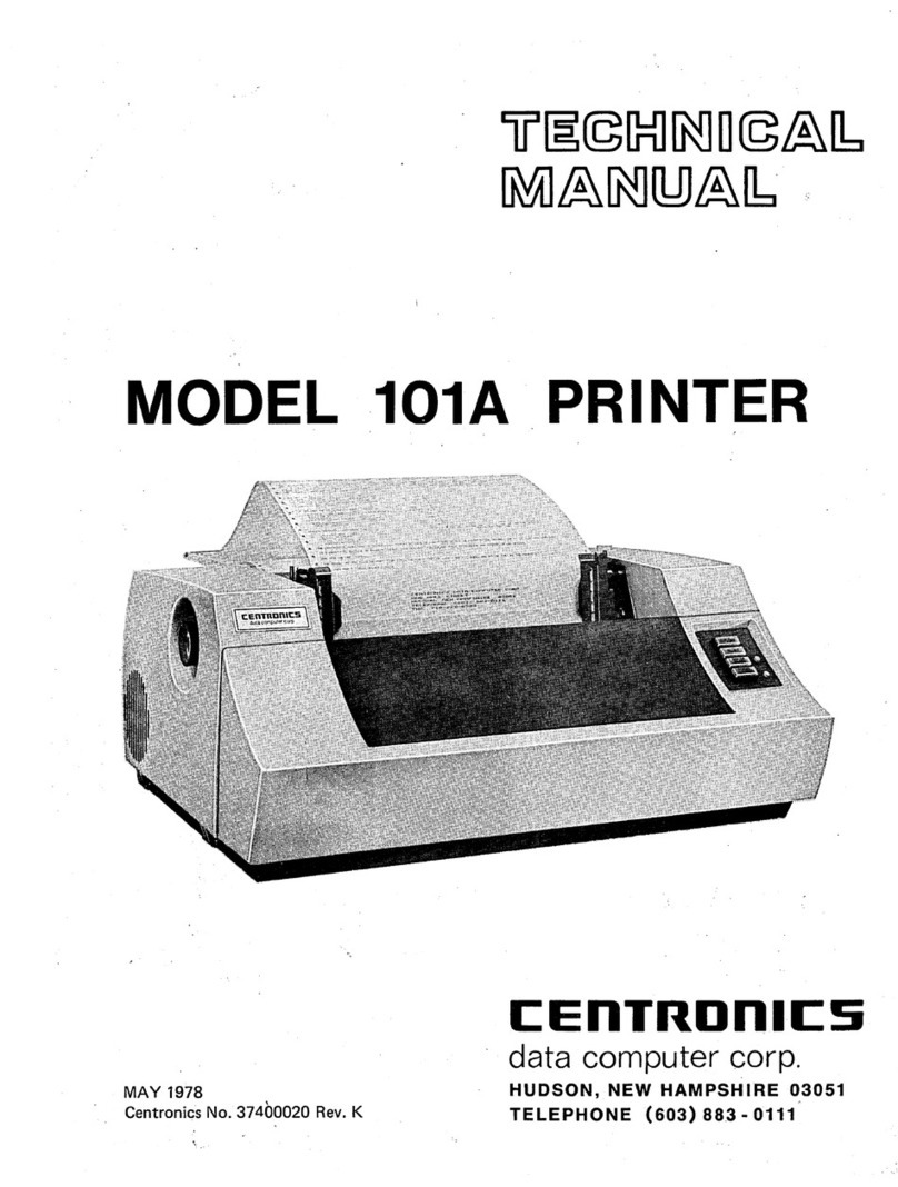
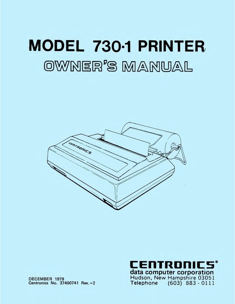
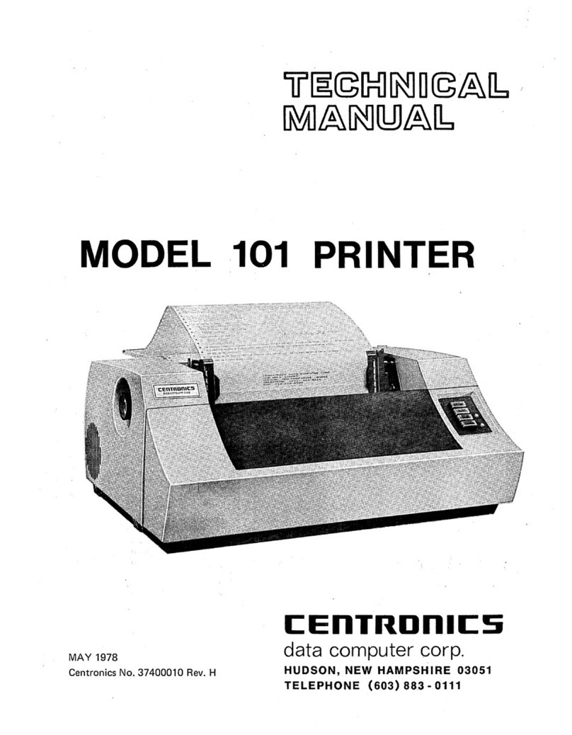
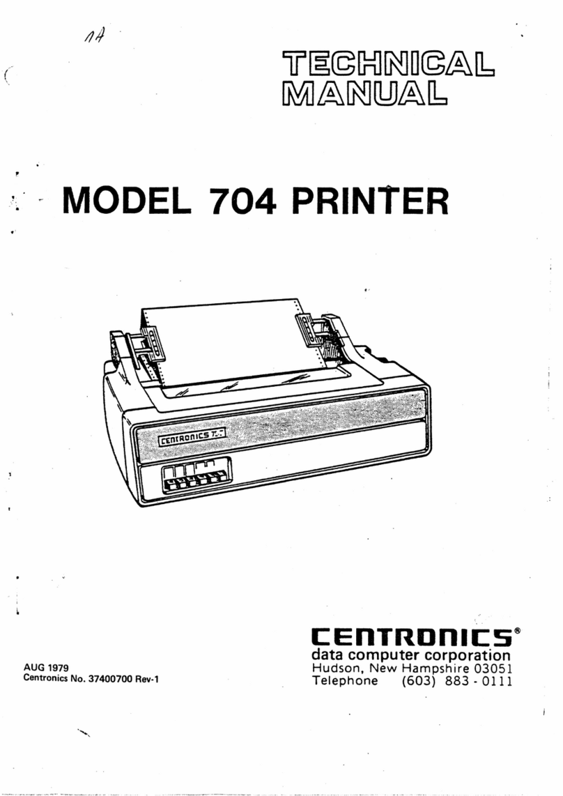
Centronics 702 User manual

C:EnTRDnlC:S
C:EnTRDnlC:S
c:
£--~----~----
..
.
--"!-~~
s
MODEL 702/703
\-1
c:
1.
PRINTER
(j
: s
37400591
REV
C AUGUST 1980
,,J
.
C:t1111~u111LS
·
C:EnTRDnlC:S
-
~
.
.,
CEnTRDn,1c:s.
CEnTRDnlCS
OPERATORS
MANUAL

TP 114 12-llO B
--WARNING--
This
equipment
generates,
uses,
and
can
radiate
radio
frequency
energy
and
if
not
installed
and
used
in
accordance
with
the
operators
manual,
may
cause
interference
to
radio
communications.
It
has
been
tested
and
found
to
comply
with
the
limits
for
a
Class
A
computing
device
pursuant
to
Subpart
J
of
Part
15
of
FCC
Rules,
which
are
designed
to
provide
reasonable
protection
against
such
interference
when
operated
in
a
commercial
environment.
Operation
of
this
equip-
ment
in
a
residential
area
is
likely
to
cause
interference
in
which
case
the
user
at
his
own
expense
will
be
required
to
take
whatever
measures
may
be
required
to
correct
the
interference.
JANUARY
1,
1981
APPROVED,
CLASS
A
Note:
Must
be
used
with
shielded
data
cables
only.

TABLE
OF
CONTENTS
SECTION
1-GENERAL
INFORMATIOM
PAGE
1.1
DESCRIPTION
.............................................................
1-1
1.2
SPECIFICATIONS
..................................
·
.........................
1-2
1.3
PRINCIPLES
OF
OPERATION
..................................................
1-3
1.4
SELECTABLE/OPTIONAL
FEATURES
........................................•...
1-5
1.5
ACCESSORIES
.............................................................
1-6
1.6
TECHNICAL
DOCUMENTATION
................................................
1·6
SECTION
2-INSTALLATION
2.1
PRINTER
INSPECTION
.......................................................
2·1
2.2
SITE
CONSIDERATIONS
......................................................
2-1
2.3
SET-UP
PROCEDURES
.......................................................
2·2
2.4
RIBBON
CASSETTE
INSTALLATION
OR
REPLACEMENT
.....................•........
2-3
2.5
LOADING
PAPER
.. . .. ... ... ... ... .... .. .
.................................•
2·4
2.6
PAPER
SPECIFICATIONS
.....................................................
2-6
2.
7
DIP
SWITCH
SETTING,
AUTO
LINE
FEED
.........................................
2-6
2.8
SELF-TEST
...............................................................
2-6
SECTION
3-INTERFACE
INFORMATION
3.1
PRINTER
INTERFACE
CONNECTIONS
............................................
3-1
3.2
INTERFACE
DRIVERS
AND
RECEIVERS
..........................................
3-1
3.3
INTERFACE
INPUT/OUTPUT
SIGNALS
...........................................
3-1
3.4
HOST-GENERATED
CONTROL
CODES
............................................
3-2
SECTION
4-0PERATION
4.1
CONTROLS
AND
INDICATORS
.................................................
4-1
4.2
OPERATING
NOTES
.........................................................
4-2
4.3
OPERATING
GUIDE
..........................................................
4·2
4.4
VERTICAL
FORMAT
UNIT,
OPERATION
..........................................
4·3
SECTION
5-0PERATOR
MAINTENANCE
5.1
PREVENTIVE
MAINTENANCE
..................................................
5·
1
5.2
TROUBLESHOOTING
GUIDE
...................................................
5-2
702/703
OM
0591-C

SECTION
1
GENERAL
INFORMATION
1.1
DESCRIPTION
The Models 702/703
are
high-speed, bidirectional,
impact printers that use dot matrix techniques for
character generation.
Each
printer is completely
self-contained, composed of mechanical, electro-
mechanical components and a logic printed cir-
cuit
board
(PCB).
The printed circuit board uses
microprocessor technology to minimize com-
ponents and increase reliability.
Maximum throughput is achieved with bidirec-
tional printing that seeks the shortest path
to
the
next line
of
characters when printing successive
lines
of
data. Print head and paper movement is
controlled by stepper motors.
The standard printer uses a 7x 7
dot
matrix and
64
upper case ASCII characters for character
generation. Character sets
of
64,
96,
128,
160
or
192
are also available. The major differences
be-
tween the Model
702
and.703 are the print speed
and paper slew rate. These differencesare shown
in paragraph
1.2
Specifications.
This manual provides the necessary information
to
install, operate and maintain the printer. This
information includes site considerations, set-up
procedures, operating instructions and operator-
level maintenance.
Figure
1-1
Model
702/703
Printer
7021703
OM
0591
·C
1-1

1.2
SPECIFICATIONS
DATA
INPUT
Data Format
...................
718
bit ASCII parallel, TTL levels
Input Code
.....................
64
character ASCII
Buffer
.........................
One line character buffer
Input Gating
..................•
Data Strobe is normally gated with acknowledge of previous
character.
PRINTING
Printing Method
................
Impact, character
by
character, bidirectional
Dot Matrix
.....
·
................
Standard: 7x 7
Optional:
5x7,
7x9,
9x7,
and
9x9
Print Format
...................
Standard:
10
characters per inch
Optional:
12
or
15
characters per inch
Print Speed
....................
MODEL
703-180
cps
(7
x 7 dot matrix)
-165
cps
(9
x 7 dot matrix)
MODEL
702-120
cps
(7
x 7 dot matrix)
-11
Ocps
(9
x 7 dot matrix)
CharacterSet
..................
Standard:
64
character
ASCII
Optional:
64,
96,
128,
160
and
192
character sets
Number
of
Copies
...............
Prints original and up to five carbon copies
PAPER
ADVANCE
Vertical Format
.................
6 lines per inch
Paper Entry
....................
Rear and Bottom Feed
PaperSlew Rate
................
MODEL
703-15
inches per second (ips)
MODEL
702-8
inches per second (ips)
Auto Line Feed
.................
Automatic line feed on carriage return (Disabled
by
option)
Paper Feed
....................
Rear or Bottom tractor feed
17.3
inches
(439
mm) maximum paper width
13.2
inches
(335
mm) maximum print width
Paper Specifications
.............
Refer to paragraph
2.6
for detailed specifications
PHYSICAL-ENVIRONMENTAL-ELECTRICAL
Height
........................
9.0
inches
(229
mm)
Depth
.........................
19.5
inches
(495
mm)
Width
.........................
25.0
inches
(635
mm)
Weight
........................
75
lbs.
(34
k_g)
Temperature
...................
Operating: 40° to 100°F
(4°
to 38°C)
Storage:
-35
° to 130°F (
-37°
to
54
°
C)
Humidity
......................
Operating: 20% to 90%
(No
condensation)
Storage: 5% to 95% (No condensation)
Input Voltage/Frequency
.........
115
VAC +10%,
-15%;
60
Hz
±1
Hz
230
VAC
+10%,
-15%;
50
Hz
±1
Hz
Power Cord Length
..............
12
feet
(3.
7
m)
702/703 OM
0591
·C
1-2

1.3
PRINCIPLES
OF
OPERATION
Figure
1-2
is a pictorial block diagram
of
the
Model
702/703
printers, illustrating the relation·
ship
of
the electrical and mechanical com-
ponents to the logic board.
The
printercontains a"microprocessor" that con-
trols printer operations. Under program control
the microprocessor, located
on
the main logic
board, controls the receiving
of
parallel data and
monitors the control panel. Also, the micro-
processor initiates movement of the print
head,
carriage and paper,
and
monitors feedback from
the limit switches, video system, optional elec-
tronic vertical format unit,
and
paper empty
switch to effect proper execution
of
these com-
mands. It maintains arecord
of
the position
of
the
print
head
at all times, provides printer status in-
formation
to
the attached devices, and performs
other housekeeping functions.
Basically, all printer functions
can
be grouped in-
to one of three categories:
(1)
character printing,
(2)
paper motion,
and
(3)
auxiliary functions.
CIRCUIT
BREAKER@
30016
INPUT
DEVICE
~TCABLE
ASSEMBLY
(W2)
ELECTRONIC
VERTICAL
FORMAT
~
UNIT
(VFU)
(OPTION)
rfV
TRANSFORMER
' .
FILTER
~--=====--<>t
SPEAKER
AUDIO
ALARM
(OPTIONAL)
~I
--~PO_w_E_R
__
D-10-DE
BRIDGES
~
.
~CITORS
PARALLEL
DATA
IN
CONTROL
RTP~
LOGIC
BOARD
•
MICROPROCESSOR
•PROGRAM
•MEMORY
•
SUPPORT
LOGIC
•
POWER
SUPPLIES
•
POWER
DRIVERS
LEFT
MARGIN
INDICATOR
~
!,..,
RIGHT
MARGIN
INDICATOR
~
EDP
(fJPAPER
EMPTY
q
~WITCH
VIDEO
PAPER
STEPPER
MOTOR
SOLENOIDS
SIGNALS
VIDEO
AMPLIFIER
HEAD
MOTION
'
TIMING'-
FENCE
""'-
'
Figure
1-2
Pictorial
Block
Diagram
PRINT
HEAD
&
CARRIAGE
ASSEMBLY
CARRIAGE
STEPPER
MOTOR
7021703
OM
0591-C
1-3

CHARACTER
PRINTING-Characters
are
printed by
selectively activating the print wires aligned in a
vertical column in the print
head.
As the head
moves across the
p~per,
the appropriate print
wires
are
momentarily activated, driving them
against the ribbon, paper
and
platen to form the
specified dot pattern.
The
print commands to the print wires
are
developed
by
programmable read-only memories
(PROM's). To extract print information, the
microprocessoraddresses a
PROM
memory loca-
tion for each column within a character.
As shown
in
Figure
1·3,
the print
head
is attached
to the carriage assembly, which in turn is at·
tached to a rotating carriage drive belt. The car-
riage is driven in the forward or reverse direction
by
the carriage stepper motor which rotates the
carriage drive belt clockwise (forward direction)
or counterclockwise (reverse direction).
VIDEO
AMP.
ASSEMBLY
PAPER
MOTION-Paper can
be
moved manually by
pushing
in
and rotating the platen knob, or
automatically by any
of
three paper motion com-
mands: line feed, vertical tab and form feed.
Paper is advanced one line
by
momentarily ac-
tivating the paper stepper motor, which applies
torque to the tractor unit drive gears. When using
the tractor unit with the electronic vertical format
option, vertical tab and form feed operations are
accomplished
by
activating the paper stepper
motoruntil the prescribed amount
of
paper move-
ment, programmed into the microprocessor, has
been accomplished.
The electronic vertical format option allows
ver-
tical tab, form feed and bottom of form operations
to
be
controlled electronically
by
data memory.
The memory can be loaded either locally through
CARRIAGE
DRIVE
STEPPER
MOTOR
ELECTRONIC
VFU
(OPTION)
20104
NOTE:
DIRECTION
SHOWN
FOR
UPWARD
PAPER
MOVEMENT.
Figure
1-3
Character
Printing/Paper
Motion
702/703 OM 0591-C 1-4

a hand-fed paper tape reader or remotely through
the reader
by
the operatoreach time the printer is
powered-up or when a format change is required.
The
memory holds the "tape image" which is
electronically "rotated"
as
paper is advanced.
If the electronic vertical format option is not used,
then a vertical tab operation moves paper 1 inch
(6
line feeds)
and
a form feed operation moves
paper
11
inches or
12
inches, as prescribed by the
customer. This feature is preset in the option
PROM,
and
also determines forms control
if
the
electronic vertical format option is installed but
memory is not loaded.
SPECIAL
FUNCTIONS-As a standard feature, the
printer contains automatic motor control which
applies a holding current to the stepper motors
when no data is received.
Also a standard feature, the printer
has
a self-test
capability which is activated
by
pressing the
OVERRIDE
switch while the printeris deselected.
The printer automatically prints
out
both
characters sets and the
h~xadecimal
equivalent
for each of the
32,
8-bit locations
in
the option
PROM.
An
optional audio alarm is available for alerting
the operator of a special condition.
An
audible
tone from a speaker is sounded
by
software com-
mand (bell
code-07
hex)
or by a paper empty
condition.
In
addition to printable character codes, the
printer also recognizes certain special control
codes. Refer to paragraph
3.4
for a list of these
control codes and the actions performed upon
receiving these codes.
1.4
SELECTABLE/OPTIONAL
FEATURES
The standard printer may be equipped with
various selectable/optional features to provide
additional capabilities in the printer.
The
features
available
are
as
follows:
SELECTABLE
FEATURES
Auto
Line
Feed
on
Carriage
Return
Disabled-On
detection
of
a carriage return
(CR)
control code,
previously received data will
be
printed, but a line
feed
(LF)
will not
be
performed.
Inhibit
Prime
on
Select-
The
feature prevents the
logic and buffer from being reset when the printer
is selected.
702/703
OM
0591-C
1-5
Inhibit
Prime
on
Delete-This feature prevents a
delete code (Octal
177)
from resetting the print
buffer. It allows the delete code to be used as a
pad
character.
Inverted
Data
Strobe-This feature inverts the
negative-going data strobe to
an
active high for
control function definition and data loading.
Non-Gated
Data
Strobe-This feature allows the
printer to accept data before the previous
character is acknowledged.
Escape
Control
of
Bit
8-
This feature enables the
software sequence
of
ESC
(Octal
033),
Numeric 3
(Octal
063),
and
ESC
(Octal
033),
Numeric 4(Octal
069)
to control the active state
of
bit
8.
Automatic
Print
on
Paper
Motion
Command-This
feature generates a carriage return on receipt
of
a
line
feed
(LF),
vertical tab (VT) ortop
of
form
(TOF)
command, causing the line of data to
be
printed
before the paper motion command is performed.
Data
Bit
8 Address-(A) Secondary character set
can
be
accessed
by
bit 8 high or low.
(B)
Single
elongated character can be controlled by bit 8
high or low. (Only
(A)
or
(BJ
can be selected.)
OPTIONAL
FEATURES
Character
Sets-Optional
64,
96,
128,
160
or
192
character sets
are
available in upper/lower case,
international or special symbols. Selection
of
an
alternate character set is done by bit
8.
The
character sets
are
available in 5x
7,
7x
7,
7x
9,
9x
7,
and 9x 9 dot matrix.
Condensed
Print-Optional
12
or
15
characters per
inch condensed print is available in place
of
the
standard
10
character per inch density.
Electronic
Vertical
Format
Unit-The
optional 2 or
12
channel electronic vertical format unit
(EVFU)
allows vertical tabs and form feed operations to
be controlled by data memory that stores "tape
image" which is electronically rotated as paper is
advanced. If the
EVFU
is not used in the printer,
then the printer automatically performs
an
11
inch form feed
and
a 1 inch vertical tab at 6 lines
per inch.
Audio
Alarm-
This option generates
an
audible
alarm approximately 2 seconds in duration in
response to a BELL code (Octal
007)
or a paper
empty condition.

6/8
LPI-
This option allows, by operator selec-
tion, printing at 6 lines per inch
or8
lines per inch.
Elapsed
Time
Indicator
(ETl)-An
optional indicator
showing up to
1000
hours of print time before it
has
to be reset, is available to the user.
1.5
ACCESSORIES
The
following printer accessories are available.
RIBBON
CASSETTE
(37740008-2001)-Throwaway
longlife ribbon cassettes containing
70
yards of
ribbon are available to the user.
UNIVERSAL
PRINTER
STAND
(81100000-6070)-The
printer stand provides a rigid pedestal for mount-
ing the printerand allows for bottom or rear paper
loading.
FORMS
RECEIVING
TRAY
(65008166-6002)-The
forms receiving tray collects and neatly stacks
forms exiting from the rear of the printer.
NOTE:
The forms receiving tray is standard when the
printer stand option is chosen.
OUIETIZED
CABINET
-The quietized cabinet is
specifically designed to absorb noise from the
in-
terior
of
the printerand along the paper path. This
accessory enables users to operate their printers
in a low noise level work environment.
FRONT
FEED
UNIT
(63703215-6001)-The front feed
unit allows users to handle ledger cards and cut
forms in either single or multipart form.
PRINTER
EXERCISER
(66000100-4001)-The printer
exerciser is a self-contained unit used for the off.
line testing
of
the printer with parallel interface.
The unit includes
19
switch selected test controls
and a
10
ft. cable.
PRINTER
MINI-EXERCISER
(6600310-4001
)-
The
mini-exerciser is a self-contained unit and
in-
cludes
an
integral connectorwith two switches to
control line length and different character forma-
tions. In combination the two switches produce
four test sequences.
7021703
OM
0591-C
1-6
PRINTER
MINI-II
EXERCISER
(66003107-5001)-A
self-contained, hand held off-line tester that tests
the parallel printer. The Mini-II is programmable
by front panel switches. A
43
inch cable is pro-
vided with the unit.
TOOL
KIT
(63002399-6001
)-A
tool kit containing
all the necessary tools (screwdrivers, nut drivers,
pliers, etc.)
to
maintain the printer is available to
the user.
1.6
TECHNICAL
DOCUMENTATION
The
following
technical
documentation
documents the Models
702
and
703
printers in
detail. Contact the Customer Service Department
at Centronics for these publications.
UNPACKING/REPACKING INSTRUCTIONS
(37407827-9001)-The unpacking/repacking
in-
structions are attached to the outside of the ship-
ping container and provides all the necessary
in-
formation to unpack the printer.
TECHNICAL
MANUALS
(Model
702-37400550-9001,
Model
703-37400450-9001
)-
The
technical
manual is used by qualified field service person-
nel. The manual contains detailed information
on
printer theory
of
operation, maintenance,
ad-
justments and removal/replacement procedures.
A print set containing schematics, assembly and
wiring diagrams for all printed circuit boards is
also contained in the manual.
ILLUSTRATED
PARTS
MANUALS
(Model
702-
37400552-9001,
Model
703-37400452-9001)-The
illustrated parts manual contains illustrations and
lists of materials detailing all assemblies and
sub-assemblies down to a piece part level. The
manual also contains a numerical index, listing
every part contained in the printer
in
numerical
order and reference to a figure and index number
to show the location of the part.
TECHNICAL
INTERFACE
MANUALS-A technical
manual covering in detail the optional interface
boards is available to the user. The specific
manual will be shipped with the installed inter-
face board.

CDCC
PART
NO.
63701381-5001
81100000-6070
65008166-6001
37740008-2003
63002399-6001
37400591-9001
37400701-9001
37400591-9001
37400453-9001
37400550-9001
37400450-9001
37400700-9001
37400453-9001
37400550-9001
37400450-9001
ACCESSORIES ORDER FORM
MODEL 702/703/704
ACCESSORY
QUANTITY
DESCRIPTION
Acoustic
Cover
Print Stand (unassembled)
Forms
Receiving Tray
"7-Meg"
Ribbon Cassette
Tool
Kit
Operators Manual (702/703)
Operators Manual (704)
Operators Manual (704-11/12)
704-11/12
Addendum
Technical
Manual (702)
Technical Manual (703)
Technical
Manual
(704)
704-11/12 Addendum
Illustrated
Parts Manual (702)
Illustrated
Parts Manual (703)
UNIT
TOTAL
PRICE
PER
ITEM
$ 40.00
150.00
38.00
178.08/doz.
56.00
9.00
9.00
9.00
N/C
35.00
35.00
35.00
N/C
20.00
20.00
SALES TAX
ORDER TOTAL
SHIP
TO:
BILL TO: (If different from "SHIP TO")
Dept. Phone Number Dept. Phone Number
Firm Name Firm Name
Address Address
City State Zip City State Zip
CustomerNumber Purchase Order Number Customer Number
Ordered by
PAYMENT METHOD:
D
UPSCOD
Payment Terms:
For orders less than $100.00:
Attention of
0 CHECK ENCLOSED
ewe pay freight) D
BILLME
(Current CDCC
Customers
only)
Will
be
shipped
UPS
COD; unless payment for the full amount of the order, including sales tax, is enclosed.
With
prepayments we pay the shipping costs.
For
orders in excess
of
$100.00:
Same terms as above; or,
if
you currently have
an
account with Centronics,
we
can bill you.
Prices subject to change without notice.

SECTION
2
INSTALLATION
2.1
PRINTER
INSPECTION
Visually inspect the printer for signs
of
damage
received during shipment. Immediately notify the
common carrier
of
any damage.
NOTE
---------.
Any
attempttooperate a
damaged
printervoids the warranty
and
may
cause further
damage.
19.5"
---i
(495mm)l
I
v-Y2tJ
2.2
SITE
CONSIDERATIONS
When selecting a site
to
install the printer, the
following information should
be
taken into con-
sideration.
PRINTER
DIMENSIONS-Refer to Figure
2·1.
00768
TABLE TOP OPERATION
32.0"
(812
mm)
702/703
OM
0591
·C
36.0"
max
-----
(914
mm)
_______
_
r--
24.5"
--1
I
~
'"'
....
,
;;::ftfl--1
t
I
l:
'-
I 20.0" I
i---1so8
mm)---j
PRINTER STAND OPERATION
Figure
2-1
Printer
Dimensions
2·1
.....
8.0"
(203mm)
j1
LJ

WEIGHT
Printer:
75
lbs.
(34
kg.)
Stand:
22.5
lbs.
(10.2
kg.)
TEMPERATURE
Operating: 40°
to
100°F
(4°
to
38°C)
Storage:
-35°
to 130°F
(-37°
to 54°C)
HUMIDITY
Operating: 20% to 90% (No condensation)
Storage: 5% to 90% (No condensation)
ELECTRICAL
115
VAC +10%,
-15%;
60
Hz
±1 Hz
230
VAC +10%,
-15%;
50
Hz
±1 Hz
Power Cord Length:
12
ft.
(3.67
meters)
POWER
INDICATOR
2.3
SET-UP
PROCEDURES
The following procedures detail the set-up
of
the
printer prior
to
operation at the installation site.
Refer
to
Figure
2-2
and perform the following:
1.
Note any discrepancies in general printer
appearance.
2.
Remove the top cover from the printer and
while manually moving the print head from left
to
right check the following:
A.
Ensure the optics block under the video
amplifier does not contact the timing
fence.
00773
$
POWER
CORD
NOTE:
ALWAYS
USE
A
3·WIRE
GROUND
OUTLET.
INTERFACE
CONNECTOR
I
Figure
2-2
Set-Up
Procedures
7021703
OM
0591-C
2-2

B.
Ensure the carriage arms do not contact
the ready to print
(RTP)
and end of print
(EOP)
switches.
NOTE
-------
If either of the above
two
conditions occurs, refer
to
the
ad-
justment section in the Technical Manual.
3.
Loosen penetration control knob, move knob
backwards away from platen, and insert ribbon
cassette and paper
as
described in paragraphs
2.4
and
2.5.
4.
Check the setting of
DIP
switch No.
1,
Auto
Line Feed Enable/Disable, per paragraph
2.7.
HEAD
PENETRATION
(SINGLE
PART
FORMS)
1.
Move _penetration control knob
as
far forward
as possible.
2.
Tighten penetration control knob.
HEAD
PENETRATION
(MULTI-PART
FORMS)
1.
While manually moving print
head
across the
page, increase print head penetration by
mov-
ing penetration control knob forward until
smudging occurs.
2.
Move penetration knob backward just to the
point
of
no smudging.
3.
Tighten penetration control knob.
PRINTER
POWER/SELECT
1.
Plug printer into appropriate
A.C.
outlet.
Always
use a 3-wire grounded outlet.
2.
Ensure power switch on rear
of
printer is
OFF
and connect printerto desired input device via
interface connector.
3.
Set power switch to the
ON
position and
check/perform the following:
A.
Ensure SELECT lamp on the operators
panel is extinguished.
B.
Press TOP OF
FORM
switch on operatoi:s
panel and rotate platen to adjust paper
to
top
of
form position.
C.
Depress SELECT switch to enable printer
to
receive data.
702/703
OM
0591-C
2-3
2.4
RIBBON
CASSETTE
INSTALLATION
OR
REPLACEMENT
The printer uses a throw-away
70
yard cassette
(37740008-2001). To install
or
replace
the
cassette, refer to Figure
2·3
and perform the
following:
1.
Turn power
off
and remove top cover.
2.
Move carriage to center position in printer.
Loosen and move penetration control knob
away from platen.
3.
If replacing existing cassette, move cassette
latch towards front
of
printer and remove
cassette, taking care not to damage ribbon
shield and guide. Discard the used ribbon
cassette.
.----------------------------
NOTE
--------------------------.
Insert the ribbon guide card supplied with the new cassette
between the ribbon shield and guide.
FRONT
COVER
Figure
2-3
Ribbon
Cassette
Installation
or
Replacement
00777

4.
Hold new cassette above print
head
and lower
it, tipping the rear edge
of
the cassette
downward so that
it
clears the edge
of
the
front cover.
5.
Lower cassette until retaining tab rests
on
sloping portion
of
retaining latch with locator
pin aligned with slot
in
cassette
and
ribbon
be-
tween rear paper guide
and
ribbon guide card.
6.
Carefully press cassette downward until latch
snaps into position above retaining
tab.
Assure the ribbon is properly positioned
be-
tween rear guide card
and
rear ribbon guide.
7.
Turn ribbon drive gear knob clockwise several
turns toassure properengagement of cassette
with cassette drive gear and
to
assure proper
ribbon movement between rear ribbon guide
and ribbon guide card.
8.
Remove ribbon guide card, reset penetration
control knob and install top cover.
2.5
LOADING
PAPER
Paper may be installed two ways
in
the tractor
drive assembly; rear feed or bottom feed. The
following procedures detail loading
of
the paper
both ways.
TRACTOR
DRIVE,
REAR
FEED
1.
Ensure power is off and remove top clear
cover. Refer to Figure
2-4.
2.
Loosen and move penetration control knob
away from platen.
3.
Release tractor feed locking levers, then
tilt
tractor feed unit back so that tractor feed
pins face up.
4.
Open
paper
guides
and feed
paper
underneath tractor assembly and up into left
pin feed tractor. Close left paper guide to
secure paper. Adjust right pin feed tractor to
accomodate paper width. Ensure paper holes
are
aligned so that top sheet is parallel with
top
of
printer. Close right paper guide.
5.
Swing tractor feed unit forward and down.
Lift column scale/tear
bar.
Release paper ten-
sioner by rotating knob upward.
6.
Feed paper under platen and rotate platen
knob until paper is fed around platen and up
between platen and column scale/tear bar to
top
of
pin feed tractors.
7.
Open paper guides and align paper so that
top of paper is parallel with top of printer.
Close paper guides.
8.
Adjust pin feed tractors so that first character
prints in desired column
on
paper.
9.
When properly adjusted, secure tractor lock-
ing levers, lower column scale/tear
bar,
ad-
just paper tension with tensioner wheel, and
readjust penetration control knob.
10.
Replace top clear cover, turn power on and
depress PRINT switch to enable printer to
receive data.
Figure
2-4
Loading
Paper,
Rear
Tractor
Drive
702/703
OM
0591-C
2-4

TRACTOR
DRIVE,
BOTTOM
FEED
1.
Ensure power is off
and
remove
top clear
cover. Refer to Figure
2-5.
2.
Loosen
and
move penetration control knob
away from platen.
3.
Release tractor
feed
locking levers.
4.
Open paper guides
and
lift column scale/tear
bar.
COLUMN
SCALE/
TEAR
BAR
5.
Place box
of
paper underneath printer
as
shown in Figure
2-5
and
feed paper up
through bottom ofprinterbetween platen and
column scale/tear bar up into tractor feed.
6.
Once paper is installed, lower column
scale/tear
bar,
close paper guides, set tractor
feed
locking levers
and
adjust penetration
control knob.
NOTE
--------.
Forbest results, remove paper from box and ensure paper is
centered and fed straight up
into
printer.
00761
TRACTOR
FEED
LOCKING
LEVER
Figure
2-5
Loading
Paper,
Bottom
Tractor
Feed
702/703
OM
0591-C
2-5

2.6
PAPER
SPECIFICATIONS
Acceptable paper is continuous fan-fold, edge
perforated paper conforming to the specifica-
tions illustrated
in
Figure
2-6.
DD763
Figure
2-6
Paper
Specifications,
Tractor
Drive
@
@
AUTO
LF
ENABLED
DIP
NO.
1
•
AUTO
LF
DISABLED
PAPER
SPECIFICATIONS,
TRACTOR
DRIVE
A.
FORM
LENGTH:
3.0"
to
14.0"
(75
mm
to
355
mm);
[11"
(279
mm)
is
recommended]
B.
PAPER
WIDTH:
12
.1
" (
307
mm)
maximum
(Other
Specifications
not
Illustrated)
FORM
THICKNESS:
0.030"
(0.75
mm)
maximum
PAPER
WEIGHT:
Single-Part
Form-15
to
20
lb
Multi-Part
Form
(5-part
maximum)-Original-12
to
15
lb
Copies-9to121b
(last
copy
151b)
Carbon
Paper-
7V2
lb
with
medium
hardner
2-.
7
DIP
SWITCH
SETTING,
AUTO
LINE
FEED
The
auto line feed is enabled
or
disabled by
DIP
NO.
1,
switch
3,
on
the operator's panel. Figure
2-7
details the setting of the switch.
2.8
SELF-
TEST
The
self-test feature is activated by depressing.
the
OVERRIDE
switch while the printer is
deselected. The printer automatically prints out
both character sets
and
the hexadecimal
equivalent for each of the
32,
8-bit locations in the
option
PROM.
@
Ill
DIP
NO.
1
CONTROL
PANEL
ASS
EMBLY
I
Remove
printer
front
cover
to
access
switches.)
DD96D
Figure
2-7
DIP
Switch
Setting,
Auto
Line
Feed
2-6

SECTION
3
INTERFACE
INFORMATION
3.1
PRINTER
INTERFACE
CONNECTIONS
A 36-pin connector (Amphenol
57
Series) located
in
the rear of the printer provides the means for
connecting the printer to the input device. The
pin-outs of the printer interface connector
are
shown below.
PIN
SIGNAL
1
DATA
STROBE
2
DATA
BIT
1
3
DATA
BIT
2
4
DATA
BIT
3
5
DATA
BIT
4
6
DATA
BIT
5
7
DATA
BIT
6
8
DATA
BIT
7
9
DATA
BIT
8
10
ACKNOWLEDGE
(ACKNLG)
11
BUSY
12
PAPER
OUT
(PE)
13
SELECT
(SLCT)
14
GROUND
15
OSCILLATOR
(OSCXT)
16
GROUND
17
CHASSIS
GROUND
18
+5V
19
TWISTED
PAIR
GROUND
20
TWISTED
PAIR
GROUND
21
TWISTED
PAIR
GROUND
22
TWISTED
PAIR
GROUND
23
TWISTED
PAIR
GROUND
24
TWISTED
PAIR
GROUND
25
TWISTED
PAIR
GROUND
26
TWISTED
PAIR
GROUND
27
TWISTED
PAIR
GROUND
28
TWISTED
PAIR
GROUND
29
TWISTED
PAIR
GROUND
30
INPUT
PRIME
RETURN
31
INPUT
PRIME
32
FAULT
33
GROUND
34
NOT
USED
35
NOT
USED
36
NOT
USED
702/703
OM
0591-C
3-1
3.2
INTERFACE
DRIVERS
AND
RECEIVERS
Figure
3-1
details the voltage range for the inter-
face drivers and receivers. The interface receivers
are
terminated
by
1k ohm resistors to +5V.
LO=
0.4V
@ 7
mA
lk
+SV
LO
=
0.4V
@ 16
mA
RECEIVER
DRIVER
HI
=
2.4V
@
0.0
mA
00955
HI=
2.4V
@
400
uA
All
input/output
signals are
TTL
compatible
Figure
3-1
Interface
Drivers
and
Receivers
3.3
INTERFACE
INPUT
/OUTPUT
SIGNALS
DATA
STROBE
(Host
Generated)-This negative
going pulse is used to transfer the incoming data
into the printer logic. The pulse duration must be
a minimum of
1.0
microsecond.
DATA
LINES
(Host
Generated)-The eight data lines
DATA
BIT
1-DATA BIT 8 contain the ASCII
character data information. Data bit levels
are
positive true logic. The high logic level
of
each
data line must
be
settled at least
1.0
microsecond
before the leading edge
of
the strobe pulse and
remain
at
high at least
1.0
microsecond after the
trailing edge
of
the strobe pulse.

INPUT
PRIME
(Host
Generated)-This signal causes
the print head
to
return to the left margin and
resets the printer logic on the trailing edge
of
the
signal.
ACKNOWLEDGE
(Printer
Generated}-This negative
going signal is used
to
verify the transfer
of
in-
coming data
or
to signify the end
of
a functional
operation. Once a code, character or control, is
sent
to
the printer,
an
acknowledge pulse must
be received before a new code can be sent.
NOTE: If the NON-GATED DATA STROBE feature
is selected, the printer can accept new data
before the previous character is acknowledged.
BUSY
(Printer
Generated)-This high going signal is
used
to
give a positive
DC
level signal indication
during the time when the printer cannot receive
data. It is also positive when the paper empty or
the fault status line is high.
EXTERNAL
OSCILLATOR
(Printer
Generated}-The
ex-
ternal oscillator
(OSCXT)
is a
90-200
kHz oscillator
used
for
external interface timing.
PAPER
EMPTY
(Printer
Generated)-A high level
signal that indicates the printer is
out
of
paper.
SELECT
(Printer
Generated)-A high level signal in-
dicating the SELECT switch has been depressed
or
a selectcode has been received and the printer
is ready
to
accept data.
3.4
HOST-GENERATED
CONTROL
CODES
Control codes are sent
to
the printer along with
character codes in the input data lines. Control
codes are interpreted as instructions by the
printer. The following table is a summary of the
control codes recognized
by
the printer.
MNEMONIC
FUNCTION
LF
Line Feed
CR
Carriage Return
DC1
Select
DC3
Deselect
VT
Vertical Tab
FF
Form Feed
DEL
Delete
so
Elongated Characters
BEL Audio Alarm
702/703
OM
0591-C
3-2
LINE
FEED
(LF)
CODE-If the printer is in the select
mode, receipt
of
the line feed code will cause im-
mediate advance of one line.
VERTICAL
TAB
(VT)
CODE-If the vertical tab code
is received while the printer is selected, the code
is processed and then acknowledged. The
ver-
tical tab code will not be processed
or
acknowledged when the printer is deselected.
If
VFU
data is loaded in the
RAM,
receipt of a
VT
code will cause paper to advance
to
the next se-
quential vertical tab location. If VFU data is not
loaded in the
RAM,
receipt
of
a
VT
code will
cause paper to advance to a pre-set default
VT
location. Default
VT
locations are located at6-line
intervals.
FORM
FEED
(FF)
CODE-If the form feed code
is
received while the printer is selected, the code
is
processed and acknowledged. The form feed
code will not
be
processed or acknowledged
when the printer is deselected.
If
VFU
data is loaded in the RAM, receipt of a FF
code will cause the paper to advance
to
the next
sequential form feed (top
of
form) location.
If
VFU
data is not loaded in the RAM, receipt
of
a
FF code will cause the paper
to
advance
to
a pre-
set default FF location. Default FF locations are
located at
66
or
72-line intervals.
CARRIAGE
RETURN
(CR)
MODE-If the printer is in
the select mode and printable characters have
been received, receipt of a carriage return code
will cause immediate printing. A carriage return
code is not acknowledged when the printer is
deselected.
OCTAL
DECIMAL
HEXADECIMAL
012
10
QA
015
13
OD
021
17
11
023
19 13
013
11
OB
014
12
oc
177 127
7F
016
14
OE
007
05 07

ELONGATED
CHARACTER
(SO)
CODE-If the printer
is selected and receives a "SO" code, characters
printed from the buffer will be elongated. This
mode will be cancelled on receipt
of
a
DEL
code,
an
end of print command,
or
an
input prime.
The number of elongated characters allowed per
printable line should not exceed one half the buf·
fer's character capacity.
SELECT
(DC1)
CODE-Receipt
of
this code selects
the printer, independent of the operator's panel.
7021703
OM
0591-C
3-3
DESELECT
(DC3)
CODE-Receipt of this code
deselects the printer, independent of the
operator's panel.
DELETE
(DEL)
CODE-If the
DEL
code is received
when the printer is in the select mode, the printer
logic will
be
reset.
AUDIO
ALARM
(BEL)
CODE-Receipt of this code
with the printer in the select mode will cause the
optional speaker to generate
an
audible tone for
approximately two seconds.

SECTION
4
OPERATION
4.1
CONTROLS
AND
INDICATORS
Figures
4-1
and
4-2
illustrate all the controls and
indicators
on
the printer mechanism and
operator's panel.
POWER
SWITCH-When set
to
the ON positon,
ap-
plies power
to
printer circuits.
PAPER
TENSIONER-Adjusts paper tension for pro-
per paper feeding.
PLATEN
KNOB-When manually pushed in and
turned, adjusts vertical paper position in printer.
PENETRATION
CONTROL
KNOB-Adjusts print head
penetration
for
optimum print quality.
SELECT
LAMP-When
lit, indicates printer is
selected.
VFU
LAMP
(Optional)-When lit, indicates optional
electronic VFU is properly loaded.
ALERT
LAMP-When
lit, indicates error condition
that is operator correctable, such as paperempty
or paper handling malfunction.
POWER
LAMP-When
lit, indicates power is on.
LINE
FEED
SWITCH-When depressed, causes
paper
to
advance one line.
TOF
SWITCH-When depressed causes paper to
advance
to
top
of
next form as governed by op-
tional Vertical Format Unit
(VFU).
00769
POWER
SWITCH
PAPER
TENSIONER
Figure
4-1
Controls,
Printer
Mechanism
702/703 OM
0591
·C
4-1
This manual suits for next models
1
Table of contents
Other Centronics Printer manuals

Centronics
Centronics 101AL Guide

Centronics
Centronics 306 User manual

Centronics
Centronics 306 User manual

Centronics
Centronics 730-1 User manual

Centronics
Centronics 352 User manual

Centronics
Centronics 101 User manual

Centronics
Centronics 101A User manual

Centronics
Centronics 704 User manual

Centronics
Centronics 101 User manual

Centronics
Centronics 101A User manual
Popular Printer manuals by other brands

Supvan
Supvan TP2000M user manual

Epson
Epson C1100 - AcuLaser Color Laser Printer instruction manual

Sony
Sony UP-D890 Instructions for use

Canon
Canon iP4200 - PIXMA Photo Printer Installation instruction

Epson
Epson Stylus Pro 7900 user guide

Custom Audio Electronics
Custom Audio Electronics VKP80III user manual