Centronics 704 User manual

-
a
.
,
«
Ln
4
AUG
1979
Centronics
No.
37400700
Rev-1
Ta
Re
mm
Rad
Seb
Oo
Mee
SOT
me
tte
eee
TECHINIGAL
MANUAL
Pens
ecient
ee
nF
nee
etn
eee
vat
CENTRONICS’
data
computer
corporation
Hudson,
New
Hampshire
03051
Telephone
(603)
883-0111

THE
INFORMATION
CONTAINED
HEREIN
[S
PROPRIETARY
AND
!IS
NOT
TO
BE
RELEASED
OR
REPRODUCED
WITHOUT
WRITTEN
PER-
MISSION
OF
CENTRONICS
data
computer
corp.
CENTRONICS
Centronics
Data
Computer
Corp.
Hudson,
N.H.
03051
Tel.
(603)
883-0111,
TWX.
(710)
228-6505,
TLX.
94-3404
Eastern
Region
(Mass.):
Tel.
(617)
935-6150
Central
Region
(Texas):
Tel.
(817)
461-5711,
TWX.
910-890-4916
Western
Region
(Calif.):
Tel.
(714)
979-6650,
TWX.
910-595-1925
Centronics
Data
Computer
(Canada)
Ltd.
Mississauga,
Ontario
Tel.
(416)
625-0770,
TWX.
610-492-4382
Centronics
Data
Computer
(U.K.)
Ltd.
London,
England
Tel.
581-1011,
TLX.
8951373
Centronics
Data
Computer
(France)
50
Rue
Dombasie,
75015
Paris,
France
Tel.
828-4051,
TLX.
202686
Centronics
Data
Computer
(Germany),
Gmbh
6000
Frankfurt
am
Main
71
Tel.
666-1021,
TLX.
841-413224
Centronics
of
Puerto
Rico
Dorado,
Puerto
Rico
Tel.
(809)
796-1881,
TLX.
385-9349
copyright
197§$
Centronics
Data
Computer
Corp.
All
rights
reserved
Patents
pending
in
U.S.A.
and
other
countries
Printed
in
U.S.A.
Specifications
subject
to
change
without
notice.
In
the
U.S.A.,
for
fast
service
call
toll
free
1-800-258-1952

TECHNICAL
MANUAL
MODEL
704
PRINTER
CENTRONICS’
data
computer
corporation
Hudson,
New
Hampshire
03051
Telephone
(603)
883-0111


TABLE
OF
CONTENTS
SECTION
1
INTRODUCTION
Section
1.1
MANUALS.
«©
2
2
«© «© «©
«© «@
1.2
GENERAL
DESCRIPTION.
.
+2
eo
e
1.3
PHYSICAL
DESCRIPTION
.
«
o«
-«
1.321
Print
Mechanism
.
.
.
12-342
Electronics.
.
«2.
e
e
123.3
Paper
Handling
Mechanism
1.4
PRINTER
OPERATION
- - +
«©
-
1-4-1
Character
Printing
-
.
124.2
Paper
Motion
.
.-
«
.e
1-4.3
Special
Functions.
e
°
1.5
SPECIFICATIONS
SUMMARY.
. . .
SECTION
2
INSTALLATION/SET-UP
2e1
INTRODUCTION
~©
«©
© ©
e©
oe
.e
202
FLOOR
PLANNING
-«©
«© «© oc
e
e
203
SET-UP
PROCEDURES
e
e e
e
e
SECTION
3
THEORY
OF
OPERATION
3e1
OVERALL OPERATION
.
+
ce o«
-«
301.1
Input/Output
Signals
°
301.2
Microprocessor
control
.
321.3
Memory
Organization.
.
3.2
MICROPROCESSOR
(MPU)
.
«©
« «
3e2e1
Architecture
e
e
e e °
e
3e2Qe2
Timing
e e
e
e
®
e e
e
36223
Basic
MPU
Operation
. . «
.e
30204
Microprocessor
Program
Control
-j-
4=3
1-3
1-3
1-4
1-7
1-7
3-4
3-4
3-6
3-6
3-9

TABLE
OF
CONTENTS
(cont'd)
Section
3.3
35
3.7
3.8
3.9
3.10
BUS
STRUCTURE»~
«©
«
o
«+
e
3.1
General
Description
.
32
Detailed
Description
033
Input
Data
Transfers.
3.4
I/O
Bus
Transfers.
.
SYSTEM
TIMING
\
e
e
ee
e@
SERIAL
COMMUNICATIONS
« «
e«
3-5-1
Input
Data
e
° ° ®
3.5.2
Output
Datae
e
°
e
CONTROL
CHARACTERS
»«
«.«
co
e
.
Firmware
Response
.
3.6.1
36-2
Control
Codese
.
.«
6
6
MRI
AND
DEVICE
SELECT
DECODING
367.1
Device
Select
.
.
.e
3e7e2
MRI
Decoding
e e
e
CONTROL
PANEL/MPU
COMMUNICATIONS
VFU
Reader/MPU
COMMUNICATIONS
PRINTER
MECHANISM
OPERATION
.
e
3-10.1
Carriage
Motor
Operation
3210-2
VIDINT
Generation
e
3e-10.3
Character
Generation.
MISCELLANEOUS
OPERATIONS
e
3-11.-1
Audio
Alarm
e
ee
e
3e11-2
Paper
Out
e
e e e
3211-3
Motor
Control
«
.
.
STEPPER
MOTOR
OPERATION
.
.-
POWER
DISTRIBUTION
~
-«©
«©
e
3-18
3-19
3-20
3-20
3-23
3-24
3-24
3-26
3-27
3-29
3-29
3-30
3-31
3-35
3-35
3-35
3-36
3-36
3<38
3-41

ATO
ng
SR
Re
MN:
IE
ree
ne
9
TABLE
OF
CONTENTS
(cont'd)
-1ii-
®
Section
SECTION
4
MAINTENANCE
4.1
INTRODUCTION
~
.«
6
«©
©
ee e«
e
4.2
PRINTER
MARKING
AND
CONFIGURATION
.
4.2.1
Centronics
Nameplate
.
.
4.262
Fuse
Marking
and
Location
.
4.2.3
logic
Board
Marking
and
Configuration
4.2.4
Dip
Switch
Settings,
Control
Panel
.
4.3
RECOMMENDED
PREVENTIVE
MAINTENANCE.
4.4
TROUBLESHOOTING
GUIDE
~
.«.
26
e«
e
4.5
RECOMMENDED
TOOLS
.©
+26
e«
e«
e
oe.
SECTION
5
ADJUSTMENTS
5
e
1
INTRODUCTION
e e e
e
‘eo
e
e
e
5.2
CHARACTER
PRINTING
ADJUSTMENTS
..
5.2.1
Penetration
Adjustment,
Print
Head
522-2
Timing
Fence
Adjustment.
.
522-3
Carriage
Actuator
Arms
Adjustment
5.2.4
Main
Drive
Belt
Adjustment.
5.3
PAPER
MOTION
ADJUSTMENTS
~
-«
e«
-«
5.3.1
Paper
Feed
Timing
Belt
Adjustment
523-2
Platen
Adjustment.
. .
.
5-323
Tractor
Drive
Timing
Belt
Tension
5.3.4
Paper
Tension
Adjustment.
5.4
ELECTRICAL
ADJUSTMENTS
2°
e
e«
5.4.1
Video
Amplifier
Adjustments
5.4.2
Logic
Board
Adjustments.
.
SECTION
6
REMOVAL/
REPLACEMENT
6.1
INTRODUCTION
~
«©
5»
© ©
«©
e«
«
6.
2
COVER
ASSEMBLIES
.
e
oe
e
e e
e
6.3
PRINT
HEAD
ASSEMBLY.
.
.
..
.
6.4
POWER
DRIVER
BOARD
ASSEMBLY
.
.
.
6.5
TIMING
FENCE
ASSEMBLY
-
2.
«
o«
.
6.6
VIDEO
AMPLIFIER
ASSEMBLY
.
. . .
4-1
4-2
4-2
4-9
4~11
4-13
5=1
5-2
5=3
5=3
5-4
5-4
5=5
5=5
5-6
5-6
5-6
5-9
6-4
6-5
6-6

TABLE
OF
CONTENTS
(cont'd)
Section
6.7
RIBBON
CARTRIDGE
ASSEMBLY
.
28
ee
6.8
LIGHTWEIGHT
CARRIAGE
ASSEMBLY
. .
.-
6.9
STEPPER
MOTOR
ASSEMBLY,
CARRIAGE
DRIVE
6.10
STEPPER
MOTOR
ASSEMBLY,
PAPER
DRIVE
.
6.11
PLATEN
ASSEMBLY
©
28
©
©
e
© 8
6.12
VERTICAL
FORMAT
UNIT
~© -© «©
© »
-»
6.13
TRACTOR
DRIVE
ASSEMBLY
°° es
e
ee
6.14
PIN
FEED
TRACTORS,
LEFT/RIGHT
.
. .
6.15
PRIMARY
VOLTAGE
ASSEMBLY
. .
.
e«
-
6.16
CAPACITOR/DIODE
BRIDGE
ASSEMBLY
2.
6.17
FAN
ASSEMBLY
* e
«©
e©
©
©
«
6.18
LOGIC
BOARD
ASSEMBLY
.
.«
.«
«
-«
.e
6.19
CONTROL
PANEL
ASSEMBLY
©
©e©
©
©
e
SECTION
7
ELECTRICAL
DRAWINGS
APPENDIX
SIGNAL
GLOSSARY
6-10
6-11
6-12
6-13
6-14
6-14
6-16
6-17
6-18
6-19
6-20

2-2
3=1
3-3
©
3=4
3-5
3-6
3-7
3=8
3-9
3-10
3-11
3-12
3-13
3-14
3-15
3-16
3-17
3-18
3-19
3-20
3-21
3-22
3-23
3-24
3-25
3-26
3-27
4-1
4=2
4=3
5-1
5=2
5=3
LIST
OF
ILLUSTRATIONS
Model
704
Printer.
.
.
.« «© e« «6
«o
« «
Major
Assemblies
~-
.«
.«
.«
«.«
«
«ce
e«
e« -e
Printer
Basic
Block
Diagram
.
. .
.«
«
-
Printer
Pictorial
Diagram.
.
. .
« «
e
Character
Printing/Paper
Motion
. . .
.e«
.e
Printer
Outline
Drawing.
.
.
.«
.« .«
e«
e
Set-Up
Proc
edur
eS
e
e
e
e
e
e
° ®
e
e
Overall
Block
Diagram
.
. .
.
«
«o«
«
.e
Memory
Map
-
+« +«
e« «©
©
e
©
©
©
«
-«
8080A
Microprocessor
Pin
Designations
.
.
.
MPU
Block
Diagram.
.
.«
+« «+
«
««
«
«
e
Typical
Output
Instruction
Cycle
Timing
. .
MPU
Status
Word
.
.
+6
«
«©
©
«© «©
«
e
Bus
Structure
Block
Diagram
. .
.« .«
« e
$1/82
MPU
Timing
Circuit
©
e ©
e «
ef
G$2BY2/P2BY8
Timing
Circuit
.
°°
©
e
©
e
Data
Bus
Assignments
(Baud
Rate
Commands).
.
Control
Panel
Status
Word
. .
-«
.«
« «
«
Exploded
Section
of
Timing
Fence.
.
.
e«
.«
Video
Amplifier
Simplified
Schematic
.
.
.
Video
Edge
Detector
Circuit/Timing
. . .
.-
Miscellaneous
Operations
.
e«
«.«
«+«
«
e« -.
Basic
Stepping
Motor
Operation
.
.-«
«+ «+
.e
Stepper
Motor
Drive
Circuit
ele
le
lls
Power
Distribution
Diagram.
.«
+
«©
«+
e e
~-
FLOW
CHARTS
-
Printer
Initialization
.~.
.«
.«
c«
-«
.«
e
«
Main
Program
Monitoring
loop
-
-«
+
e«
e
e
Print
Routine
~.
.
«.«
«-
e«
©
«e«
«e«
se
e
-«
Video
Interrupt
Routine.
.
.«
e«
« e
e
e
Carriage
Drive
Interrupt
Routine.
.
.
.«
.
Paper
Drive
Interrupt
Routine.
.«
.
.«
e«
e
Control
Character
Interrupt
Routine.
.
.
.
VFU
Paper
Tape
Load
Routine
. .
.«
.«
e e
Control
Character
Interrupt
Routine.
.
.
.
Centronics
Nameplate.
. .
+« e«
.«
e
e«
«
logic
Board
Marking
«©
-«
+« e«
«
«
e
«
e
Dip
Switch
Setting
(Control
Panel)
-
.
-«
.-
Recommended
Tools
© 8
©
© ©
©
«© e@
-@
Penetration
Adjustment
(Print
Head
Assembly).
Timing
Fence
Adjusttment
.
-«
+«
«
oc
«
-e
Carriage
Actuator
Arms
Adjustment
-.
+
« -
==
2~1
2-3
3-0
3-2
3-4
3-5
3-7
3-8
3-10
3=17
3-18
3-19
3-27
3-30
3-31
3-32
3-36
3-38
3-39
3-41
3-42
3-43
3-44
3-45
3-46
3-47
3-48
3-49
3-49
4-1
4-2
4-3
4-13
5=2
52
5=3

oy
Ongena
a
8
Eo
San
cc
amg
Figure
5-4
5=5
5-6
5-7
5-8
5-9
5-10
5-11
6-1
6-2
6-3
6-4
6=5
6-6
6-7
6-8
6-9
6-10
6-11
6-12
6-13
6-14
6-15
6-16
6-17
7=1
7-2
7=3
7-4
7=5
7-6
7=7
7-9
7-10
LIST
OF
ILLUSTRATIONS
Main
Drive
Belt
Adjustment.
. .
Paper
Feed
Timing
Belt
Adjustment
Platen
Adjustment
©.
©
©
©
-»
Tractor
Drive
Timing
Belt
Tension
Paper
Tension
Adjustment
. .
«
Optical
Pickup/Timing
Fence
Alignment
Optical
Pickup,
Vertical
Alignment
.
Duty
Cycle
and
Phase
Adjustment
of
Video
~
REMOVAL/
REPLACEMENT
-
Cover
Assemblies
~-
.«
.«
.«
e«
Print
Head
Assembly
~ .
.« e«
e-
Power
Driver
Board
Assembly
.
.
Timing
Fence
Assembly
.
.
.«
«
Video
Amplifier
Assembly
.
.
.
Ribbon
Cartridge
Assembly
. . .
Carriage
Assembly
°°
8
e©
«©
e
Stepper
Motor
Assembly,
Carriage
Drive.
Stepper
Motor
Assembly,
Paper
Drive.
Platen
Assembly
.
.-«
.«
.«
o «
Vertical
Format
Unite
. .
e«
.
Tractor
Drive
Assembly
Pin
Feed
Tractors,
Primary
Voltage
Assembly
..
.
Capacitor/Diode
Bridge
Assy
.
.
Fan
Assembly
.« -«
«
6
e«
e«
«
Logic
Board
Assembly.
. .
«
«
Control
Panel
Assembly
.
. . .
~-
FUNCTIONAL
SCHEMATICS
=
Data/IO/Address
BuS
«©
.«
.«
«=
.«
Input
Data
~
.«
«©
«©
«©
©
ee
«@
Device
Select
.
.«
«
.«
.o«
«
e
Control
Panel/MPU.
° °
e
e °
VFU
Reader/MPU.
e e
e .
e e
CG/STM/CRM/MPU.
.«
e«
«©
©
e«
e
-
SCHEMATIC
DIAGRAMS
Logic
Board
©
6 © © ©
«
e
Power
Driver
Board
.~
.«
+e
«
.e
Video
Amplifier
Board
.
.
.
.-
Control
Panel
Board
.
.
»«
«
.
e
o
5-4
5-4
5=5
5-5
5-6
5-7
5-7
5-9
6-0
6=3
6-4
6-5
6-6
6-7
6~9
6-10
6-11
6-12
6-13
6-15
6-16
6-17
6-18
6-19
6-20
7=3/7=4
7-5/7-6
7=7/7-8
7-9/7=10
7=11/7=12
7~13/7-14
7-18
_
7=19
72
1
7-22

Figure
7=11
7-12
7=13
7=14
7-15
7-16
7~17
LIST
OF
ILLUSTRATIONS
-
WIRING
DIAGRAMS
-
Interconnecting
.
.«
« «
e«
e
Primary
Voltage
.
.«
+2«
e«
e
-»
-
ASSEMBLY
DIAGRAMS
logic
Board
.~
.
.«
«©
«
e« e«
Power
Driver
Board
~«
.«
c+
.e.
e
Video
Amplifier
Board
. .
.«
.e
Control
Panel.
.«.
+
«
«+c
©
e
I/O
EIA
Cablee
.«
«©
©
c©
eo
e
-vii-
7-23
7-24
7=26
7-28
7=29
7=30
7=31

“Naas

2s
caer
cee
me
ep
SECTION
I
INTRODUCTION
1.1
MANUALS
This
technical
manual
is
part
of
a
series
providing
complete
documentation
for
the
Model
704.
The
three
manual
series,
with
part
numbers,
is
listed
below.
TITLE
PART
NO.
Technical
Manual
37400700
Operator's
Manual
37400701
Illustrated
Parts
Breakdown
Manual
37400702
1.2.
GENERAL
DESCRIPTION
(Figure
1-1)
The
Model
704
is
a
132=-column,
dot
matrix
printer
with
an
intergrated
RS=-232C
asynchronous interface
and
a
9-foot
EIA
input
cable.
The
printer
uses
microprocessor
technology
and
prints
bidirectionally.
Maximum
throughput
is
achieved
with
the
bidirectional
print
head
which
seeks
the
shortest
path
to
the
next
line
of
data
when
printing
successive
lines
of
data.
Print
speed
is
180
characters-per-second
for
the
standard
7x7
dot
matrix.
Stepper
motors
control
print
head
and
paper
movement.
A
six
key
control
panel
and
DIP
switches
are
used
for
operator
control.
The
logic
board
contains
circuitry
for
receiving
serial data
from
a
data
set
or
modem.
The
RS=-232C
interface
portion
of
the
logic
provides
serial-to-parallel
data
conversion,
buffers
each
data
character
and
generates
interrupts
to
synchronize
the
microprocessor
with
the serial
data
communications
link.
.
The
remainder
of
the
logic
consists
of
a
256
character
input
buffer,
a
132
character
print
buffer
and
PROM's
for
firmware
storage
and
character
generation.
Print
mechanism
control
circuits
provide
the
final
output
to
the
print
head
and
stepper
motors
for carriage
motion
and
paper
movement.
00501
Figure
1-1.
MODEL
704
PRINTER
1=1

1.3
PHYSICAL
DESCRIPTION
(Figure
1-2)
The
printer
is
completely
self-contained,
including
the
printer
mechanism
with
micoprocessor
electronics
and
integral
power
supplies.
Optional
features
are
available
to
adapt
the
printer
to
specific
needs.
;
The
printer
covers
include
several
plastic
covers
and
one
sheet
metal
cover.
The
top
cover,
the
two
side
covers,
and
the
front
cover
are
plastic, and
the
rear
cover
is
sheet
metal.
The
front cover
has
an
opening
°
for
the
control
panel
in
the
lower
left
corner.
10208
TRACTOR
PAPER
FEED
A!
ELECTRONIC
VFU
a
Yo
(OPTIONAL)
ee
PAPER
TENSIONER
PLATEN
KNOB
Het
omnen
[ES
VF
\
<—
=
Ne
SPEAKER
(AUDIO
ALARM)
EAR
BAR
CONTROL
PANEL
PRINTER
STAND
(OPTIONAL)
Figure
1-2.
MAJOR
ASSEMBLIES
*
.
‘Neepeen'
ee
OO
a

The
printer
consists
of
three
major
units:
the
print
mechanisn,
the
electronics,
and
the
paper
handling
mechanism.
1.3.1
PRINT
MECHANISM
The
print
mechanism
consists
of
the
carriage
assembly,
drive
mechanism
and
print
head.
The
drive
contains
a
stepper
motor
which
drives
a
continuous
belt
that
transports
the
print
head
and
carriage
assembly
back
and
forth
along
the
platen.
1.3.-2
ELECTRONICS
Printer
control
is
provided
by
the
electronics
which
consists
of
the
input
power
transformer,
DC
power
supply,
video
amplifier,
logic
card,
and
power
driver
board.
The
logic
card
contains
the
RS-232C
serial interface,
microprocessor,
firmware,
control
logic,
and
power
supply
regulators.
The
power
driver
board
is
located
in
front
of
the
printer
behind
the
front
cover.
It
provides
the
drive
signals
for
the
print
head
solenoids
and
stepper
motors.
The
video
amplifier
receives
pulses
from
a
timing
fence
to
synchronize
the
head
firing.
1-3-3
PAPER
HANDLING
MECHANISM
The
paper
handling
mechanism
is
a
tractor
feed
unit
accommodating
fan-fold
forms
up
to
17.3
inch
wide
with
a
13.2
inch
maximum
print
width.
The
printer
has
a
rear
paper
feed
and
a
bottom
paper
feed.
Both
can
handle
up
to
six-part
forms
at
a
slew
rate
of
15
inches
per
second
(ips).
The
standard
vertical
line
spacing
is
6
lines
per
inch
(lpi)
with
8
lpi
optional.
1.4
PRINTER
OPERATION
(Figure
1-3,
1-4)
Figure
1-3
is
a
basic
block
diagram
of
the
printer,
and
Figure
1-4
isa
pictorial
diagram
illustrating
the
particular
printer
components
and
how
they
relate
to
the
main
logic
board.
The
printer
uses
a
microprocessor
that
controls
printer
operations.
Under
program
control,
the microprocessor,
located
on
the
logic
board,
controls
the
receiving
of
serial data
via
the
I/O
controller
chip
and
monitors
the
control
panel.
Also,
the microprocessor
initiates
movement
of
the
print
head
carriage
and
paper,
and
monitors
feedback
from
the
limit
switches,
video
system,
optional
electronic
vertical
format
unit
(EVFU),
and
the
paper
empty
switch
to
effect
proper execution
of
these
motion
commands.
It
maintains
a
record
of
the
position
of
the
print
head
at
all
times,
provides
printer
status
information
to
the
attached
devices,
and
performs
other
“housekeeping”
functions.

OPTION
PORT®
*Option
port
can
accommodate
devices
such
as,
character
buffer
option
board.
CONTROL
DATA
»
MICROPROCESSOR
CONTROL
WRITE
PULSES
PRINT.
a
DATA
SET
OR
SERIAL
DATAIN
MEMORY
&
SUPPORT
LOGIC
HEAD
INPUT
DEVICE
|
STATUS
LINES
eee
L_—_—__._
*
DATA
INPUT
©
PRINT
COMMAND
HEAD
MOTION
one
CONTROL
*
PAPER
MOVEMENT
OPERATOR
SWITCHES,
INDICATORS
CONTROL
*
SPECIAL
FUNCTIONS
PANEL
CONTROL
PAPER
MOTION
paren
CONTROL
READY
TO
END
OF
PAPER
PRINT
PRINT
EMPTY
SWITCH
SWITCH
SWITCH
VIDEO
1,2
SPEAKER
VIDEO
SySTEM
&
Aupio
TIMING
OPTION
FENCE
)
Figure
1-3.
VFUCHI-VFUCHI2
ELECTRONIC
VERTICAL
FORMAT
UNIT
OPTION
PRINTER
BASIC
BLOCK
DIAGRAM
10210
CARRIAGE
STEPPER
MOTOR
LIN
FEED
(PAPER)
STEPPER
MOTOR
Basically,
all
printer
functions
can be
grouped
into
one
of
three
categories:
(1)
character
printing,
(2)
paper
motion,
and
(3)
auxiliary
functions
such
as
automatic
motor
control,
audio
alarm,
etc.
1.4.1
CHARACTER
PRINTING
(Figure
1-5)
In
the
printer,
characters
are
printed
by
selectively
activating
the
print
wires
aligned
in
a
vertical
column
in
the
print
head.
As
the
head
moves
across
the
paper,
the
appropriate
print
wires
are
momentarily
activated,
driving
them
against
the
ribbon,
paper
and
platen
to
form
the
specified
dot
pattern.
Nene’

ELECTRON
VERTICAL
FORMAT
UNIT(VEU)
(OPTION)
Xe
LEFT
MARGIN
INDICATOR
RIGHT
MARGIN
INDICATO
CIRCUIT
BREAKER
re
TRANSFORMER
FILTER
_
RB,
DIODE
BRIDGES
PAPER
STEPPER
MOTOR
PAPER
{MOVEMENT
SOLENOIDS
SIGNALS
79
LOGIC
BOARD
®
MICROPROCESSOR
@
PROGRAM
e
MEMORY
PRINT
HEAD
&
CARRIAGE
ASSEMBLY
@
SUPPORT
LOGIC
POWER
SUPPLIES
POWER
DRIVERS
VIDEO
|
HEAD
MOTION
TIMING
FENCE
CARRIAGE
STEPPER
MOTOR
CONTROL
PANEL
PAPER
EMPTY
SWITCH
R
EOP
Figure
1-4.
PRINTER
PICTORIAL
DIAGRAM

20104
TRACTOR
DRIVE
BELT
PLATEN
PIN
FEED
TRACTOR
PAPER
ORIVE
CARRIAGE
ORIVE
BELT
=|}
&
ELECTRONIC
VFU
(OPTION)
VIOEO
AMP.
a
ASSEMBLY
PRINT
HEAD
CARRIAGE
ASSEMBLY
RIBBON
CARTRIDGE
¢
CARRIAGE
DRI
STEPPER
MOTOR
Figure
1-5.
CHARACTER
PRINTING/PAPER
MOTION
The
print
commands
to
the
print
wires
are
developed
by
programmable
read-only
memories
(PROM‘s).
To
extract
print
information,
the
microprocessor
addresses
a
PROM
memory
location
for
each
column
within
a character.
As
shown
in
Figure
1-5,
the
print
head
is
attached
to
the
carriage
-
assembly,
which
in
turn
is
attached
to
a
rotating
carriage
drive
belt.
The
carriage
is
driven
in
the
forward
direction
or
in
the
reverse
direction
by
the
carriage
stepper
motor which
rotates
the
belt
clockwise
(forward
direction)
or
counterclockwise
(reverse
direction).
1-6
-
ic

1.4.2
PAPER
MOTION
(Figure
1-5)
Paper
can
be
moved
manually
by
pushing
in
and
rotating
the
platen
knob,
or
automatically
by
any
of
three
paper
motion
commands:
line
feed,
vertical
tab
and
form
feed.
Torque
from
the
paper
stepper
motor
is
applied
to
the
tractor
drive
gears.
Paper
is
advanced
one
line
by
momentarily
activating
the
paper
stepper
motor,
which
turns
the
drive
gears
to
advance
paper
by
one
line.
When
using
the
tractor
unit
with
the
electronic
vertical
format
option,
vertical
tab
and
form
feed
operations
are
accomplished
by
activating
the
paper
stepper
motor
until
the
amount
of
paper
movement
programmed
into
the
microprocessor
has
been
completed.
The
electronic
vertical
format
option
allows
vertical
tab,
form feed
and
bottom
of
form
operations
to
be controlled
electronically
by
data
memory.
The
memory
can
be
loaded
either
locally
through
a
hand-fed
paper
tape
reader
or
remotely
by
downstream
loading
on
the
data
lines.
The
paper
tape
must
be
pulled
through
the
reader
by
the
operator
each
time
the
printer
is
powered-up
or
when
a
format change
is
required.
The
memory
holds
the
“tape
image"
which
is
electronically
“rotated"
as
paper
is
advanced.
If
the
electronic
vertical
format
option
is
not
used,
then
a
vertical
tab
operation
moves
paper
1
inch
(6
line
feeds)
and
a
form
feed
operation
moves
paper
11
inches
or
12
inches,
as
prescribed
by
the
customer.
This
feature
is
preset
in
the
option,
PROM,
and
also
determines
forms
control
if
the
electronic
vertical
format
option
is
installed
but
memory
is
not
loaded.
1.4.3
SPECIAL
FUNCTIONS
As
a
standard
feature,
the
printer
contains
an
automatic
motor
control
which
turns
off
the
carriage
and
paper
stepper
motors
when
no
data
is
received.
The
motors
are
then
automatically
turned
on
whenever
a
print
_
OF
paper
motion
command
is
received.
Also
as
a
standard
feature,
the
printer
has
a
self-test
capability
which
is
activated
by
depressing the
OVERRIDE
switch
while
the
printer
is
deselected.
The
printer
automatically
prints
out
both
character
sets
and
the
hexadecimal
equivalent
for
each
of
the
32,
8=-bit
locations
in
the
option
PROM.
An
optional
audio
alarm
is
available
for
alerting
the
operator
of
a
special
condition.
An
audible
tone
from
a
speaker
is
sounded
by
software
command
(bell
code
- 07,¢)
or by
a
paper
empty
condition.
In
addition
to
printable
character
codes,
the printer
also
recognizes
certain
special
control
codes.
Refer
to the
operators
manual
for
a
list of
these
control
codes
and
the
actions
performed
upon
receiving
these
codes.

1.5
SPECIFICATIONS
SUMMARY
'
Baud
Rate
eo ce
©
e
Data
Format
«
«
e«
e
Input
Code
.«
« «
-«
Buffers
eo
28©
©
&©
@
@
Line
Protocol
. .
.«
EIA
DATA
e e
e
e
o
° 9
e
(Buffer
Full
Indication)
Printing
Method
. .
Dot
Matrix
e ®
e e
Print
Formate.
.
.
.«
Number
of
Copies.
.
Character
Set
«
e«
e
Print
Speed
«
«
«
«
Vertical
Format
.
.-
Paper
Entry
«
«
«
-«
Auto
Line
Feed.
«
.-«
Paper
Feed.
«
«
e« -@
Switches
.
-«
«
«
e
IndicatorS
«.
«
e e
Manual
Controls
.
.
INPUT
«
110,150,300,
1200,2400,4800,9600
(switch
selectable)
-
1
start
bit,
7
data
bits,
1
parity
bit,
and
1
or
2
stop
bits.
This
data
word
must
contain
10
or
11
bits.
-
96
character
ASCII
«
One
line
print
buffer
and
256
character
input
buffer.
«
X~On/X-Off
or
Reverse
Channel
or
Data
Terminal
Ready
(switch
selectable)
-
Impact,
character
by
character,
bidirectional
e
Standard
-
7x7
dot
matrix
(7
pins
high),
7x9
or
9x9
dot
matrix
(9
pins
high)
e
10
characters
per
inch
«
Prints
original
and
up
to
five
carbon
copies
e
Standard:
96
character
ASCII
Optional:
96
character
sets
¢
180
cps
(7x7
dot
matrix)
165
cps
(9x7
or
9x9
dot
matrix)
PAPER ADVANCE
-
6
lines
per
inch
-
Rear
and
Bottom
Feed
-
Automatic
line
feed
on
carriage
return
(DIP
switch
selectable)
e
Rear
or
Bottom
Tractor
Feed
17.3
inches
(439
mm)
maximum
paper
width
13.2
inches
(335
mm)
maximum
print
width
CONTROLS
AND
INDICATORS
eo
ee
ee
8
8
@
«
Standard:
Power,
Select,
LF,
Override
and TOF
Optional:
Double
LF,
6/8
LPI
«
Standard:
Power,
Select
and
Alert
Optional:
Audio
Alarm
-
Forms
Thickness,
Paper
Advance,
Paper
Tensioner
|
'
PYHSICAL/ENVI
RONMENTAL/ELECTRICAL
Height.
«
»«
«
0
e«
«
Depth
«
«
«
«
»
«
e«
Width
.«
«
«
«
«
« e
Weight.
+
«
«
«
« e
Temperature
.«
«
»
e«
Humidi
ty
e e
e
e
e
Input
Voltage
.«
.
-»
A
aR
A
FREE
ENR
ym
A
Sime
Nate
engi
pena
«
8.0
inches
(203
mm)
«
19.5
inches
(495
mm)
«
24.5
inches
(622
mm)
«
60
lbs
(27Kg)
(without
stand)
«
Operating:
40°
to
100°F
(44°
to
38°C)
Storage:
-35°
to
130°F
(-379°
to
55°9¢C)
e
Operating:
20%
to
90%
(No
Condensation)
Storage:
5%
to
95%
(No
Condensation)
-
60
Hz;
115VAC,
+10%/-15%
of
nominal
.
50
Hz;
230VAC,
+10%/-15%
of
nominal
1-8
|
-
Table of contents
Other Centronics Printer manuals

Centronics
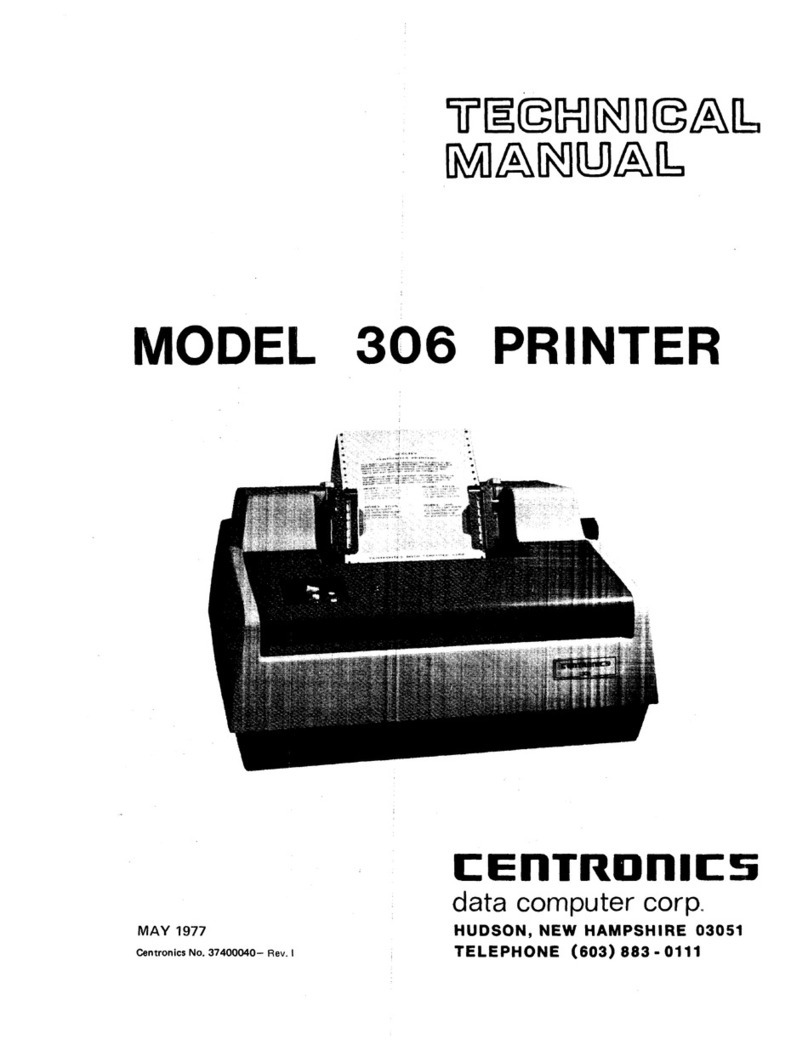
Centronics 306 User manual

Centronics
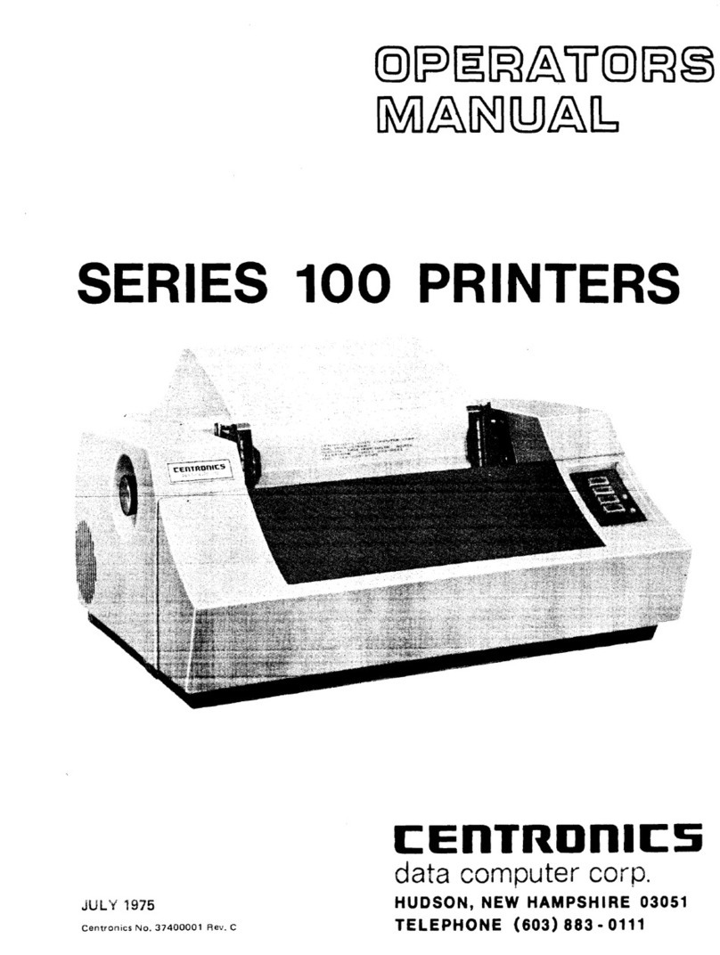
Centronics 101A User manual

Centronics
Centronics 101 User manual

Centronics
Centronics 101 User manual

Centronics
Centronics 352 User manual

Centronics
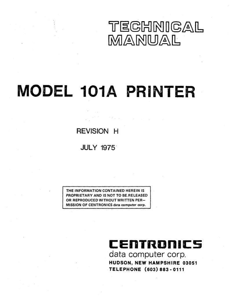
Centronics 101A User manual

Centronics
Centronics 702 User manual

Centronics
Centronics 101AL User manual
Centronics
Centronics 730-1 User manual
Centronics
Centronics 306 User manual