Centronics 101A User manual

MODEL 101A PRINTER
REVISION H
JULY 1975'
THE
INFORMATION CONTAINED HEREIN
IS
PROPRIETARY
AND
IS
NOT
TO
BE.RELEASED
OR
REPRODUCED WITHOUT WRITIEN
PER-
MISSION
OF CENTRONICS data computer corp.
I:EnTRDnll:S
data computer corp.
HUDSON,
NEW
HAMPSHIRE
03051
TELEPHONE
(603)
883·
0111


TABLE
OF
CONTENTS
SECTION
1
INTRODUCTION
Section
1.1
GENERAL
DESCRIPTION.
. .
1.2
1.3
1.4
LOGIC
FLOW
DIAGRAM
.
PRINTER
OPERATION
.
1.3.1
1.3.2
1.3.3
Character Printing . . . . . . •
Paper
Movement.
. . . . . .
Special Functions.
.....
SYSTEM
CHARACTERISTICS.
. .
1.4.1 Specifications
Summary.
. . .
1.4.2
Standard
and
Optional
Features .
1.5
PHYSICAL
DESCRIPTION
. . . . . . .
SECTIONS
2
AND
3
INSTALLATION
AND
OPERATION
2.1
SITE
PREPARATION
2.2
2.3
4.1
4.2
4.3
SHIPPING
CRATE
PAPER
GUIDE
AND
STACKER
ASSEMBLY
SECTION
4
THEORY
OF
OPERATION
INTRODUCTION.
. . . • .
BASIC
TIMING.
. . . .
INITIALIZING
THE
PRINTER.
.
4.3.1
Prime
Circuit.
. .
4.3.2 Select Circuit. . .
i
1-2
1-3
1-4
1-4
1-5
1-6
1-6
1-6
1-6
1-8
2-1
2-2
2-3/2-4
4-1
4-3
4-3
4-4
4-7
Rev.
H

TABLE
OF
CONTENTS
(cont'd)
Section
4.4
LOADING
DATA
4.4.1
4.4.2
4.4.3
4.4.4
4.4.5
4.4.6
Genera
1 • •
Da
ta Strobe . . . . .
Acknowledge
•...
Busy
Timing
. . • . . . . . . . . .
Clocking
Input
Data
Into the Buffer
..
Function
Decoder
•....
4.5
CHARACTER
PRINTING
..•.........
4.5.1 Initiating the Printing Operation.
4.5.2 Print
Head
Motion
........
.
4.5.3 Character Registration
and
Timing.
4.5.4 Character Generator
(ROM)
....
.
4.5.5 Print
Head
Operation
......
.
4.5.6
Power
Driver Circuits
......
.
4.5.7
Terminating
the Printing Operation.
4.6
PAPER
MOVEMENT
..
Line
Feed
Form
Feed
. . . • . .
4.6.1
4.6.2
4.6.3
4.6.4
4.6.5
4.6.6
Vertical
Tab.
. • . . .
...
Vertical
Format
Unit
......
.
Paper
Time
Out
Circuit. • .
Line
Feed
Solenoid
Driver.
4.7
SPECIAL
FUNCTIONS
4.7.1
Bell
.•.
~
..
4.7.2 Delete. '
..
.
4.7.3
Paper
Empty
......
.
4.7.4
Motor
Control
(Optional).
4.7.5 Fault
Circuit.
4.8
POWER
SUPPLIES
. . .
4.8.1
+5V
Regulator
.•.........
4.8.2
+12V
and
-12V
Regulators
......
.
4.8.3
+35V
Power
Supply, Unregulated.
ii
Page
·
4-10
4-10
· .
4-10
·
4-13
·
4-13
·
4-16
· .
4-18
·
4-19
·
4-19
·
4-21
·
4-21
·
4-26
·
4-27
. . . . . . . . .
4-29
· . . . . .
4-30
·
4-31
4-31
. . . . . . .
4-33
. . .
4-35
·
4-36
·
4-37
·
4-37
·
4-37
· .
4-37
· .
4-37
· .
,4-39
· . . . . .
4-39
· . . . . .
4-43
.
..
4-43
·
4-46
· 4-47/4-48
· 4-47/4-48
Rev.
0

TABLE
OF
CONTENTS
(cont'd)
SECTION
5
REMOVAL,
REPLACEMENT
AND
ADJUSTMENT
PROCEDURES
Section
5.1
5.2
INTRODUCTION
MECHANICAL
ASSEMBLIES.
5.2.1
5.2.2
5.2.3
5.2.4
5.2.5
5.2.6
5.2.7
5.2.8
5.2.9
5.2.10
5.2.11
5.2.12
5.2.13
Cover
(A).
. . . . . . . . . . . .
Carriage
Mechanism
(HA)
.
..
..
.
Driving
Mechanism
(HB).
.
..
..
.
Spring
Drum
(HC).
. . . . . .
Damper
(HD)
. . . . . . . . . .
Frame
(HE)
. . . . . . . .
Paper
Feed
Meehani
sm
(HF).
..
.
Pin
Feed
Unit
(HF)
.
..
.
Form
Feed
Mechanism
(HH). .
Ribbon
Feed
Mechanism
(HI)
..
.
Electrical
Hardware
(HJ)
..
..
.
Paper
Stacker
and
Guide
. . . . . . . .
Printer
Head
and
Associated
Assemblies
.
SECTION
6
MAINTENANCE
6.1
ADJUSTMENTS
.••..•
6.2
PREVENTIVE
MAINTENANCE
••
SECTION
7
DRAWINGS
AND
PARTS
LISTS,
ELECTRICAL
SECTION
8
DRAWINGS
AND
PARTS
LISTS,
MECHANICAL
APPENDIX
A
SIGNAL
GLOSSARY
APPENDIX
B
PARALLEL
INTERFACE
SPECIFICATIONS
iif
Page
.5-1
.5-]
5-2
5-3
5-7
5~18
5-19
5-20
5-24
5-26
5-28
5:-32
5-41
5-41
5-41
. .6-1
.6-2
Rev.
H

Figure
1-1
1-2
1-3
1-4.
1-5
1-6
1-7
1-8
1-9
2-1
4-1
4-2
4-3
4-4
4-5
4-6
4-7
4-8
4-9
4-10
4-11
4-12
4-13
4-14
4-15
4-16
4-17
4-18
4-19
4-20
ILLUSTRATIONS
Model
lOlA
Printer (Front
Cover
Removed)
Basic
Block
Diagram
••..
Printing the Letter
(H)
••••
Print
Head
Components
Paper
Movement
Mechanism
.
. . . . . . . .
..
Left Front
View
of
lOlA
Printer
••.
Right Front
View
of
lOlA
Printer
Rear
Vi.ew
of
lOlA
Printer
•••••
Rear
View
(lOlA
Electronics Cavity
Removed).
Printer
Dimensions
. • . • . • • • • •
Model
lOlA
Functional
Block
Diagram.
Functional
Flow
Chart.
Basic
Timing
Circuit .
Prime
Timing
. • • • •
Prime
Circuit
.•..•
Select Circuit
.•••
Input
Data
Timing -No
Busy
Condition
Data
Input Circuit • • • •
Acknowledge
Circuit
••••
Page
· 1-2
· 1-3
1-4
1-4
· . • 1-5
. • 1-9
• 1-9
· 1-10
· 1-10
•
2-1
·
4-1
· 4-2
· . . 4-3
· 4-4
4-5/4-6
· 4-8
• 4-10
••••
4-11/4-12
• • • 4-13
Input
Data
Causing
Busy
.•.
Busy
Circuit
.•••
~
.•
• • • • • • • 4-14
• . . • • •
4-15
Function
Decoder
. • . . •
Character Printing
Block
Diagram
••
Forward
and
Reverse
Clutch
Drive
Circuits
••.
Character
Timing
• • • . • • • • . • • • • • • .
Character Registration
and
Timing
Circuit.
Normal
and
Elongated
Characters.
Solenoid Positions, 1 through 7
.•
Print
Head
Timing
.••
Power
Driver
Waveform.
• • • • •
iv
·
4-17
• 4-19
·
4-20
•
4-22
• 4-23/4-24
•
4-27
•
4-28
•
4-28
4-29
Rev.
H

Figure
4-21
4-22
4-23
4-24
4-25
4-26
4-27
4-28
4-29
4-30
4-31
5-1
5-2
5-3A
5-3
5-4
LIST
OF
ILLUSTQATIONS
(cont'd)
Line
Feed
Circuit.
Line
Feed
Timing.
Form
Feed
and
Vertical
Tab
Circuit.
Form
Feed
and
Vertical
Tab
Timing
.
Bell Circuit
..
Paper
Empty
Location of
Motor
Control Circuit .
Motor
Control
Board
Interconnection
Diagram
.
Motor
Control
Timing.
Fault
Circuit.
Power
Distribution
Diagram.
~~odel
101
Series
Drive
Train.
Main
Motor
Drive
and
Belt Arrangements.
Bushing
End
Play
Adjustment
for Preload Clutch Shaft
(HB-50)
Flexible
Timing
Fence
Mounting,
Series
101
.
Location of Left
Reed
Switch
(Top
View)
5-4A
Two
Adjustments,
Gear
with Stop
Cam
(HH-23)
and
Inside
Page
4-32
4-33
4-34
4-35
4-38
4-40
4-41
4-41
4-43
4-44
4-45
5-7
5-9
5-18
5-22
5-24
Cam
(HH-14)
5-31
5-5
5-6
5-7
5-8
5-9
5-10
Ribbon
Feed
Mechanism
(Rear
of
Printer,
Left Side).
Backlash Adjustment,
Bevel
Gear·
(HI-43, 59) .
Driving Slide Shaft A - Adjustment.
Ribbon
Reversing
Rod
Adjustment
Ribbon
Reverse
Timing
.
Fibre Optics
Head,
Adjustment
from
Optic
Fence
.
5-36
5-37
5-38
5-39
5-40
5-45
5-11
Fibre Optics
Head
Alignment
and
Flexible
Timing
Fence
5-45
7-1
7-2
7-3
7-4
7-5
7-6
7-7
Schematic
Electronic
Card
No.
l(Sheet 1 of
3)
Schematic
Electronic
Card
No.
1 (Sheet 2 of
3)
.
Schematic
Electronic
Card
No.
1 (Sheet 3 of
3)
.
Schematic Electronic
Card
No.
2 (Sheet 1 of
3)
.
Schematic Electronic
Card
No.
2 (Sheet 2 of
3)
.
Schematic
Electronic
Card
No.
2 (Sheet 3 of
3)
.
Schematic
Power
Driver
Board
(Sheet 1 of
2)
v
7-3
7-4
7-5
7-6
7-7
7-8
7-9
REV.
H

Figure
7-8
7-9
7-10
7-11
7-12
LIST
OF
ILLUSTRATIONS
(cont'd)
Schematic
Power
Driver
Board
(Sheet 2
of
2).
Schematic
Video
Amplifier.
Schematic
+5
Volt
Regulator .
+ '
Schematic
-12
Volt
Regulator.
Multitap
50/60
Hz
Transformer
7-13
Wiring
Diagram,
Printer
Mechanism
• • •
7-14
Interconnection
Diagram,
Connector
Board
(lOlA)
•
7-15
7-16
7-17
7-18
7-19
7-20
7-21
7-22
7-23
7-24
7-25
7-26
7-27
7-28
8-1
8-2.
8-3
8-4
8-5
8-6
8-7
8-8
8-9
8-10
8-11
8-12
Schematic,
Motor
Control.
. • •
Component'Card
Assembly,
No.1.
Component
Card
Assembly,
No.2.
•
Component
Board
Assembly,
Power
Driver
Board
.
Video
Amplifier
and
Cable
Assembly.
Component
Board
Assembly,
+5
Volt
Regulator.
+
Component
Board
Assembly,
-12
Volt
Regulator •
Component
Board
Assembly,
Connector
Board
.
Component
Board
Assembly,
Motor
Control
Motor
Control
Harness
Assembly
Electronics Cavity
Assembly
Harness
(WI)
Assembly. •
Computer
Input
Cable
(W2)
Assembly.
Power
Cable
(W3)
Assembly.
Foam
Cover
Assembly
(A)
.
Carriage
Mechanism
(HA)
.
Drive
Mechanism
(HB)
Spring
Drum
{He)
Damper
(HD)
.
Frame
(HE)
Paper
Feed
Mechanism
(HF)
.
Pin
Feed
Mechanism
(HG)
.
Form
Feed
Mechanism
(HH)
•
Ribbon
Feed
Mechanism
(HI)
..
...
Electrical
Hardware
(NO
DRAWING)
(HJ). .
Print
Head
and
Associated
Assemblies
vi
Page
7-10
7-11
7~12
7-12
7-14
7-15
7-16
7-17/7-18
7-19
7-
21
7-
23
7-
25
7-,27
7-.29
7-:31
7-33
7-35
7-37
7-39
7-41
7-43
8-3
8-5
8-7
8-9
8-11
8-13
8-15
8-17
8-19
8-21
8-23
8-24
REV.
H

SECTION
1
INTRODUCTION
This
manual
describes the
Model
lOlA
printer,
manufactured
by
Centronics
Data
Computer
Corporation.
It
provides general information, detailed theory of
operation
and
maintenance
information enabling field service personnel to
main-
tain the printer.
For
serial input
or
other detailed interface information, a
separate
document
for
each
interface is published for
your
reference.
pose.
The
manual
is
grouped
into eight sections,
each
with
its
specific pur-
Section 1 -
INTRODUCTION,
introduces the reader to the
scope
and
content of the
manual,
and
provides the reader
with
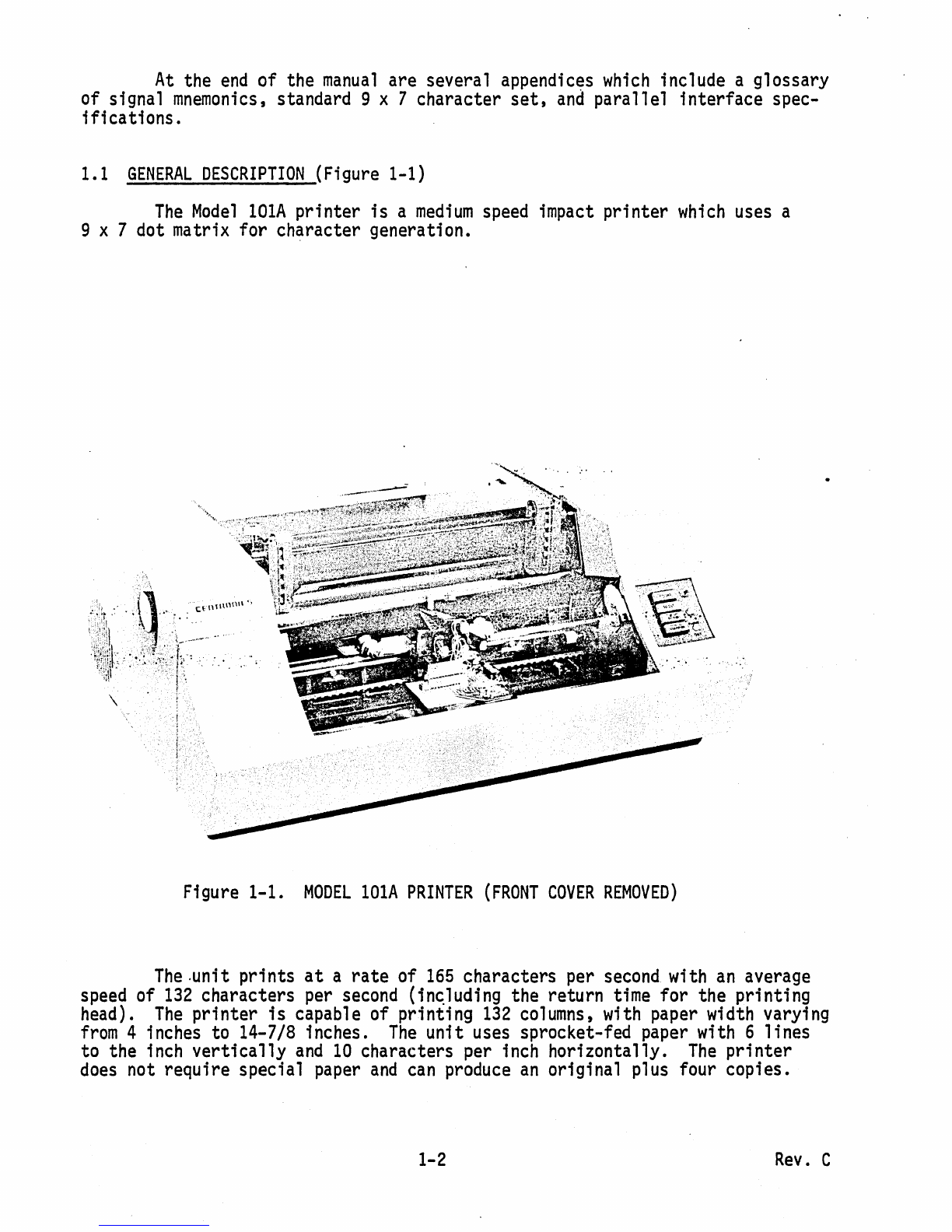
a general description of the printer.
Section 2 &3 -
INSTALLATION
&
OPERATION,
contains additional in-
stallation
and
operation data not included
in
the
Operators
Manual.
Section 4 -
Section 5 -
Section 6 -
Section 7 -
Section 8 -
THEORY
OF
OPERATION,
contains a detailed description
of
each
major
operation
performed
by
the printer
electronics, including
flow
chart,
timing
diagrams
and
circuit
diagrams.
REMOVAL,
REPLACEMENT
AND
ADJUSTMENT
PROCEDURES,
includes
step-by-step
removal
and
replacement procedures for
all
major
assemblies
and
sub-assemblies in the printer.
MAINTENANCE,
includes preventive
maintenance
procedures,
and
recommended
spare parts
list.
ELECTRICAL
DRAWINGS
AND
LIST
OF
MATERIALS,
contains a
complete
set
of schematic, wiring
and
component
board
layout
diagrams
and
their associated
list
of materials
for the electrical portion of the printer.
MECHANICAL
DRAWINGS
AND
PARTS
LISTS,
includes
all
printer
assembly
drawings
and
their
associated part
lists
for the
mechanical
portion of the printer.
1-1
Rev.
C

At
the
end
of the
manual
are several appendices
which
include a glossary
of signal
mnemonics,
standard 9 x 7 character
set,
and
parallel interface spec-
ifications.
1.1
GENERAL
DESCRIPTION
(Figure 1-1)
The
Model
lOlA
printer
is
a
medium
speed
impact
printer
which
uses
a
9 x 7 dot matrix for character generation.
\
,-
-
Figure 1-1.
MODEL
lOlA
PRINTER
(FRONT
COVER
REMOVED)
The
.unit prints
at
a rate of
165
characters per
second
with
an
average
speed
of
132
characters
per
second
(in~luding
the return
time
for the printing
head).
The
printer
is
capable of printing
132
columns,
with
paper
width
varying
from
4 inches to 14-7/8 inches.
The
unit
uses
sprocket-fed
paper
with
6 lines
to the
inch
vertically
and
10
characters per
inch
horizontally.
The
printer
does
not require special
paper
and
can
produce
an
original plus four copies.
1-2
Rev.
C

1.2
LOGIC
FLOW
DIAGRAM
(Figure
1-2)
The
132-character input buffer
can
receive parallel
data
at a rate of
up
to 75,000 characters
per
second.
If
the
input
device transmits serial
data
(100-9600
Baud),
then
an
optional
RS232
interface
is
required to
assemble
the
serial data,
then
transfer
it
in
parallel
to
the
input buffer
in
the printer.
PARALLEL
INPUT
(STANDARD)
RATE
-75,000
CHARACTERS
PER
SECOND
MARK
-
BINARY
1-+2.4
to 5.5
VOLTS
SPACE
-
BINARY
0 • 0
TO
+0.4
VOLT
DATA~
DATA
STROBE-u--u-
ACKNOWLEDGE
~
RS232
SERIAL
INPUT
(OPTIONAL)
BAUD
RATE
-
100-9600
START
PULSE
-
ONE
BIT
TIME
STOP
PULSE·
MIN.
OF
ONE
BIT
TIME
MARK
•
BINARY
1
,.
-3
TO
-27
VOLTS
SPACE
-
BINARY
0 -
+3
TO
+27
VOLTS
1.
PRINT
COMMANO
(CR
OR
LAST
CHAR.)
2.
PAPER
MOVEMENT
(LF,
VT,
FF)
3.
SPECIAL
FUNCTIONS
(BELL,
DELETE,
EXP.
CHAR,
SELECT,
DESELECT)
Figure
1-2.
BASIC
BLOCK
DIAGRAM
HEAD
MOTION
CONTROL
PAPER
~OTION
CONTROL
TIMING
Once
a line of printable characters
is
stored
in
the
buffer,
head
motion
is
initiated
by
activat1ng
the
forward
clutch, causing
the
print
head
to
move
from
left
to right across
the
paper.
With
the
head
in
motion,
data
is
transmitted
from
the
buffer to
the
character generator.
From
there, character
write pulses
are
sent to
the
driver
circuits,
which
energize
the
print
head
solenoids causing the print wires to
form
the characters
on
the
paper.
Paper
movement
is
initiated
by
a line feed, vertical
tab
and
form
feed
function.
The
Vertical
Format
Unit
(VFU)
tape
reader
provides vertical
tab
and
top
Of
form
spacing
control
by
means
of a perforated
paper
tape.
In
addition,
the
printer recognizes
the
following special control codes:
bell,
delete,
select,
de-select
and
elongated character,
as
described
in
Section 1.3.3.
1-3
Rev.
C

1.3
PRINTER
OPERATION
Basically,
all
printer functions
can
be
grouped
into
one
of the
following three categories:
1)
character printing,
2)
paper
movement,
and
3)
other auxiliary functions
such
as
printer select/deselect, delete, etc.
1.3.1
CHARACTER
PRINTING
(Figures 1-3, 1-4)
A
small
aluminum
carriage supports the
print
head
assembly.
During
printing operation, the carriage travels
along
the
print
line
from
left
to
right.
Printing
is
accomplished
by
selectively firing the
print
wires
as
the print
head
moves
from
left
to
right
across the print
line.
Printing
impulses energize the print solenoids
and
drive the
print
wires against the
ribbon,
paper
an~
platen to
form
the characters
in
a dot
matri~
pattern.
When
the solenoids are de-energized, the wires are
withdrawn
so
they are flush
with the surface of the jewel.
Each
solenoid
can
fire
independently
up
to
five times for anyone character.
F~gure
1-3
shows
an
example
of the dot
matrix
forming
the
letter
H.
All
character formations in the standard 9 x 7
dot matrix are
shown
in the Series
100
Operators
Manual.
JEWEL
~-A-~
Figure 1-3.
PRINTING
THE
LETTER
(H)
Figure 1-4.
PRINT
HEAD
COMPONENTS
The
print
head
(Figure 1-4) consists of the jewel, casting
and
seven
solenoids with attached
print
wires.
The
seven
print solenoids
and
their
attached print wires
are-
arranged radially
around
the
print
head.
The
free
ends
of the
print
wires pass through a wire guide
at
the front of the
print
head,
which
properly spaces the wires
so
that
the correct wire passes through
the correct hole
1'n
the
print
jewel.
Printing action
is
initiated
when
the input buffer
has
been
filled
or
a carriage return
(CR)
code
has
been
received.
The
print
head
then
sweeps
across the
page
until a
CR
command
is
decoded
at
the buffer output or the
head
reaches the
132-column
limit
(right) switch.
At
this
time, the
print
head
re-
turns to the
left
margin
and
an
automatic
line
feed
is performed.
As
an
option,
the automatic line
feed
can
be
disabled.
REV.
H

1.3.2
PAPER
MOVEMENT
(Figure 1-5)
Paper
can
be
moved
manually
by
rotating the platen
knob
or automatically
by
any
of three paper
movement
commands:
line feed, vertical tab
and
form
feed. .
STOP
CAM
PAPER
ADVANCE
Figure 1-5.
PAPER
MOVEMENT
MECHANISM
'v
FORM
FEED
HOLE
A
small
independent
motor
not
shown
in Figure 1-5, provides the
power
necessary to
move
the sprocket-feed tractors
which
control paper
movement.
To
move
the paper, the printer electronics activates a line
feed
solenoid
which
activates a clutch
that
mechanically links the
motor
to the sprocket-feed
tractors.
.
To
initiate
a single
line
feed, the
form
feed
solenoid
is
energized
from
15
milliseconds.
For
paper slewing, a
dc
level
is
applied to the
form
feed solenoid allowing paper to
advance
until the Vertical
Format
Unit
(VFU)
deactivates the level.
Upon
completion of the line
feed
command,
a
60-90
millisecond delay
is
generated.
This
allows the clutch
pawl
and
clutch
mechanism
to return hole before another line
feed
is
allowed.
To
initiate
a single line feed, the
form
feed
solenoid
is
energized
for
15
milliseconds.
For
paper slewing, a
de
level
is
applied to the
form
feed
sol'enoid allowing paper to
advance
until the Vertical
Format
Unit
(VFU)
deactivates the level.
The
VFU
is
controlled
by
a paper tape,
which
uses
one
track for
top
of
form
indication
and
one
track for vertical tab.
The
movement
of
the·
paper tape
is
caused
by
direct
mechanical
linkage to the gear
train
which
drives the paper
feed
tractors.
1-5
REV.
H

When
the printer
runs
out of paper, a sensing switch activates a
two-second
audible
tone
in
a speaker located
at
the rear.
The
printer also
st~ps
printing
and
lights the
PAPER
EMPTY
light
on
the control panel.
1.3.3
SPECIAL
FUNCTIONS
In
addition to the printable characters
shown
in
Appendix
B,
the
printer
can
recognize the following special functions:
Carriage return
(Octal
015)
-
Initiates
the printing of a
line.
Form
Feed
(Octal
014)
-
Moves
the
paper
until the next hole
in
Tape
Reader
Channel
7
is
reached.
Vertical
Tab
(Octal
013)
-
Moves
the
paper
until the next hole
in
Tape
Reader
Channel
5
;s
reached.
Line
Feed
(Octal
012)
-
Advances
the
paper
one
line.
Delete
(Octal
177)
-
Initializes
the printer electronics
and
clears the
buffer.
Bell
(Octal
007)
-Generates a
two-second
audible
tone
in the speaker
at
the rear of the printer.
Select
(Octal
021)
-
Allows
printer to receive data,
same
as
acti-
vating
SELECT
switch.
De-Select
(Octal
023)
-Inhibits printer
from
receiving data,
same
as
deactivating
SELECT
switch.
1.4
SYSTEM
CHARACTERISTICS
1.4.1
SPECIFICATIONS
SUMMARY
The
Model
lOlA
printer contains
all
the features described .in the
previous sUb-sections of
this
manual.
Some
of these features, in addition to
a
few
characteristics of this
manual
not previously
mentioned,
are
summarized
in the following specifications:
Printing
Method
Printing
Rate
-Characters
-Full
Lines
-Short
Lines
Transmission
Rate
-Serial
-Parallel
Impact
t character-by-character,
one
line
at
a time.
165
characters
per
second
60
lines
per
minute
(132
character line)
200
lines
per
minute
(20-30 characters)
100
to
9600
baud
(with Serial option)
Up
to 75,000 characters per
second
1-6
REV.
H

Data
Input
Character Structure
Code
Inidcator-Switch Controls
Indicator
Manual
Controls
Character Buffer
Format
Paper
Feed
Paper
Number
of
Copies
Dimensions
Weight
Electrical
Requirements
Temperature
-Operating
-Storage
Humidity
-Operating
-Storage
1.4.2
STANDARD
AND
OPTIONAL
FEATURES
Vertical
format
control
Audio
alarm
Elongated
boldface characters
(line-by-line)
Parallel data input
Parallel (Serial option available)
9 x 7 or 5 x 7 dot matrix, 10-point
type
equivalent
USASCII
-
64
characters printed,
lower
case characters recognized
and
printed
as
upper
case equivalent.
ON/OFF,
SELECT,
TOP
OF
FORM,
FORMS
OVERRIDE,
LINE
FEED
PAPER
OUT
Form
Thickness,
Paper
Advance
Knob
132
characters
(1
line)
132
characters
maximum
per
line,
6 lines
per
inch
Sprocket feed,. adjustabl e
from
4"
to 14-7/8
11
width
Standard sprocketed
paper
Original
and
up
to four
carbon
copies
11~1I
high,
20"
deep, 27-3/4
11
wide
118
pounds
115
VAC
!10%
60
Hz
115/230
VAC
t10%,
50
Hz
(option)
40
0 to
100
0F
-40
0 to
160
0F
5%
to
90%
(no
condensation)
0%
to
95%
Foreign
and
other character sets
Serial
communication
interfaces
Popular
parallel interfaces
Automatic
motor
control (eliminates
standby noise)
1-7
.
REV.
H

standard
features
Prints original plus for copies
Fixed
vertical/horizontal
registration
Paper
runaway
inhibit
(6
second
time
out)
Gated
strobe pulse (data input)
Sepa
ra
te
prime
l'i
ne
and
fau
1t 1i
ne
to
output connector
Provision for additional character
set
Remote
select/deselect
50
or
60
Hertz t
115
or
230
Volts
AC
Automatic
line
feed
disabled
by
jumper
QPt.io.n~I·f~~tures~
Selectable single character elongation
Elapsed
time
indicator
Expanded
character sets
(up
to
128
characters)
1.4
PHYSICAL
DESCRIPTION
(Figures 1-6 through 1-9)
The
printer
is
approximately
11~"
high,
20"
deep, 27-3/4"
wide
and
weighs
approximately
118
pounds.
The
referenced figures contain
different
photographic
views
of the
printer
taken with the covers
removed.
Each
major
printer
assembly
is
located
on
these figures
and
identified in the table
below
the photo.
1-8
REV.
H

1. Print
Head
Assembly
2.
Carriage
4.
VFU
Tape
Reader
5.
Pin
Feed
Mechanism
7.
Spring
Drum
8. Platen
Knob
10.
Timing
Fence
11.
Main
Drive
Belt
3.
Fonn
Feed
Mechanism
6.
Ribbon
Feed
Mechanism
9.
Damper
Figure
1-6.
LEFT
FRONT
VIEW
OF
lOlA
PRINTER
1. Operator
Control
Panel
5.
Optical
Pick-Up
9.
Penetration
Control
Knob
2.
Form
Feed
Motor
6.
Optic
Bundle
3.
Video
Amplifier
and
Cable
Assembly
7.
Ribbon
Cable
10.
Forward
Clutch
11.
Main
Pulley
and
Drive
Belt
4.
Light
Source
8.
Power
Driver
Board
12.
Reverse
Clutch
Figure
1-7.
RIGHT
FRONT
VIEW
OF
lOlA
PRINTER
1-9
13.
Cooling
Fan
14.
Ribbon
Feed
Mechanism
15.
Line
Feed
Rev.
C

4
1. Electronics
Cavity
4.
+5VDC
Power
Supply
7.
Input
Connector
10.
Fuses
2.
Electronic
Card
1
5.
t12VDC
Power
Supply
8.
Speaker
11.
In-Line
Fuse
3. Electronic
Card
2
6.
+30
Volt
Power
Supply
9.
AC
Power
Input
Figure 1-8.
REAR
VIEW
OF
lOlA
PRINTER
,
--:-.
"
..,
..
-.
1.
Main
Motor
4. Electronics
Connector
7.
Ribbon
Reversing
Rod
2.
Motor
Starting Capacitor
5.
Power
Transformer
8.
Ribbon
Drive
Rod
3.
AC
Power
Connector
6.
Power
Distribution
Figure 1-9.
REAR
VIEW
(lOlA
ELECTRONICS
CAVITY
REMOVED)
1-10

SECTIONS
2
AND
3
INSTALLATION
AND
OPERATION
Aseparate operators
manual
contains
most
of the
installation,
set-
up
and
operating procedures for the
Model
lOlA
printer.
This
operators
man-
ual
should
be
referred
to
during
normal
printer installation
and
operation.
Included
on
the following
pages
is
additional information not contained
in
the operators
manual.
2.1
SITE
PREPARATION
(Figure
2-1)
Aline
drawing
of the printer
dimensions
is
shown
in Figure 2-1.
As
shown
in
this
drawing,
the
width
of the installation
site
must
take into
account the side covers in
an
opened
position.
WEIGHT:
118
POUNDS
Figure 2-1.
PRINTER
DIMENSIONS
2-1
Rev.
C

Enviromental
and
electrical requirements
at
the installation
site
are
as
follows:
Temperature:
40
0
to
100
0 F (Operating)
-40
0 to
160
0 F (Storage)
Humidity:
5%
to
90%
(no
condensation) -Operating
0%
to
95%
-Storage
Electrical:
117
VAC
±10%,
60
Hz,
5
amps
117/234
VAC
±10%,
50
Hz,
5
amps
2.2
SHIPPING
CRATE
The
printer
is
shipped
in a crate approximately
20
inches high,
27
inches
deep
and
32
inches
wide.
The
crate
is
made
of weatherized,
triple-
walled
cardboard·
When
properly strapped, the
packing
crate
and
printer is .
capable of fork
lift
operation
with
a seven-high stacking capability.
Shipped
with
the printer are the following items:
(1)
If
a special interface
is
used, the 1nterface card
is
included
with
the printer.
For
certain interfaces
such
as
the
RS232,
a
special cable is also shipped.
Cabling
requirements for the
standard parallel interface are defined
in
Appendix
B.
(2)
A standard vertical
format
paper
tape providing six line feeds
(one
inch) for
each
vertical tab
and
66
line feeds
(11
inches)
for
each
form
feed
code.
This
tape is a part of the Vertical
Format
Unit.
Refer
to the Operators
Manual
for duplicating the
existing tape, or
if
a different
format
is
desired, for generating
a
new
tape. .
(3)
Documentation
-
All
documentation
describing that particular
printer
is
included in a plastic
bag
under
the printer.
This
doc-
umentation
includes a technical
manual
for the printer
and
any
optional interface,
and
a notice of
all
approved
changes
incor-
porated in the printer but not
documented
in the
manual.
Please
keep
this
documentation
with
the printer
at
all
times
so
that
accurate information will
be
available for troubleshooting purposes.
(4)
Pin
Feed
Knobs
-
These
knobs
are contained in a
small
plastic
bag
stapled to the guide
bar
for the pin feed unit.
(5)
Print
Sample
- A
sample
printout
from
that
particular printer
is
included
in
the
upper
paper
pan.
(6)
Unpacking/Repacking
and
Set-up Instruction Sheet.
Shipped
in a separate container
is
the
paper
guide
and
stacker
assembly.
Installation instructions for this
assembly
are included
with
the
'assembly
and
also in Section 2.3.
2-2
Rev.
H
Other manuals for 101A
2
Table of contents
Other Centronics Printer manuals

Centronics
Centronics 306 User manual

Centronics
Centronics 101 User manual

Centronics
Centronics 730-1 User manual

Centronics
Centronics 306 User manual

Centronics
Centronics 702 User manual

Centronics
Centronics 704 User manual

Centronics
Centronics 101A User manual

Centronics
Centronics 101AL User manual

Centronics
Centronics 101 User manual

Centronics
Centronics 352 User manual