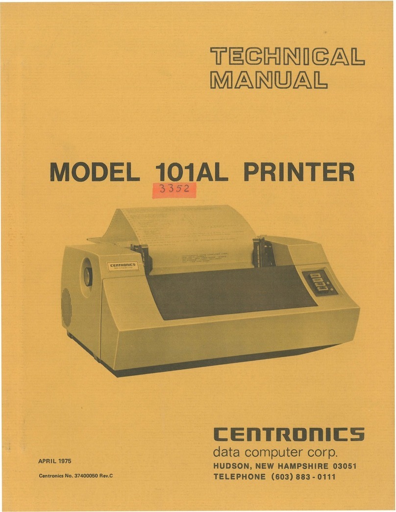
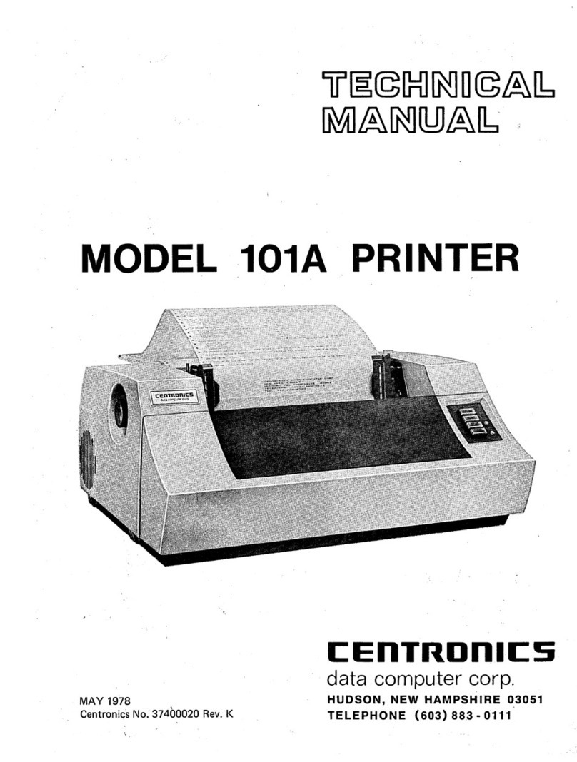
Centronics 101AL Guide

1J~@(g]
~
U
@&J::J
[Mt]&~O:JJ&~
MODEL 101AL PRINTER
MAY
1H77
Cen1tronics No.
37400050
Rev. E
I:EnTROnll:S
data computer corp.
HUDSON,
NEW
HAMPSHIRE
03051
TELEPHONE
(603)
88_3
-0111

iJ§©IM1~U©&lb
[M{J&~
U:JJ&lb
MODEL 101AL PRINTER
MAY
1977
REVISION F
THE
INFORMATION
CONTAINED
HEREIN
IS
PROPRIETARY AND
IS
NOT TO
BE
RELEASED
OR
REPRODUCED
~ITHOUT
WRITTEN
PER-
MISSION OF CENTR!ONICS
data
computer
corp.
;
!I:EnTROnll:s
ft
:data computer corporation
Hudson,
New
Hampshire
03051
Telephone
(603)
883
-
0111


SECTION
1.1
1.2
1.3
1.4
2.1
2.2
2.3
4.1
4.2
4.3
4.4
4.5
4.6
4.7
4.8
4.9
4.10
5.1
5.2
6.1
6.2
6.3
6.4
6.5
TABLE OF CONTENTS
SECTION 1
INTRODUCTION
General
Description.
. . . . . .
Logic
Flow
Diagram (Figure 1-2)
Printer Operation
.....
.
Specifications . . . . . . . . .
SECTIONS 2
AND
3
INSTALLATION
AND
OPERATION
Site Preparation (Figure 2-1) . . . . . . . .
Shipping
Crate.
. . . . . . . . . . . . .
Paper Guide and Stacker Assembly (527001001)
SECTION 4
THEORY
OF
OPERATION
Introduction
Basic
Timing
Initializing the
Printer.
-.
Data
Input
. . . . . .
Shift
Register (Buffer) .
Character Printing
Paper
Movement.
. .
Special Functions
Power Supplies
Outputs From LSI
Chips.
SECTION 5
REMOVAL,
REPLACEMENT
AND
ADJUSTMENT
PROCEDURES
Introduction
. . . . . .
Mechanical Assemblies
5.2.1
5.2.2
5.2.3
5.2.4
5.2.5
5.2.6
5.2.7
5.2.8
5.2.9
5.2.10
5.2.11
5.2.12
5.2.13
Cover . . . . . .
Carriage Mechanism.
Driving Mechanism
Spring
Drum
Damper
.....
F
rallle.
. . . . .
Paper
Feed
Mechanism
Pin
Feed
Unit
. . . .
Form
Feed
Mechanism
Ribbon
Feed
Mechanism.
Electrical
Hardware.
. . .
Paper Stacker
And
Guide . . . . .
Print
Head and Associated Assemblies.
SECTION 6
MAINTENANCE
Electrical Adjustments
Mechanical Adjustments
Preventive Maintenance (P.M.)
Troubleshooting Guide . .
Recommended Tools . . . . .
-i-
PAGE
1-1
1-2
1-3
1-5
2-1
2-1
2-2
4-1
4-1
4-1
4-4
4-8
4-9
4-15
4-19
4-22
4-24
5-1
5-1
5-1
5-2
5-5
5-14
5-14
5-15
5-19
5-21
5-24
5-28
5-34
5-34
5-35
6-1
6-1
..
6-2
6-4
6-6
Rev. f

Rev.
F
SECTION
FIGURE
1-1
1-2
1-3
1-4
1-5
1-6
1-7
1-8
1-9
2-1
2-2
4-1
4-2
4-3
4-4
4-5
4-6
4-7
4-8
4-9
4-10
4-11
4-12
4-13
4-14
4-15
5-1
5-2
5-3
5-4
5-5
5-6
5-7
5-8
5-9
5-10
5-11
5-12
5-13
5-14
5-15
5-16
5-17
5-18
TABLE OF CONTEI\ITS
CONTINUED
SECTION 7
DRAWINGS
AND
LISTS OF MATEFHALS,
ELECTRICAL
SECTION 8
DRAWINGS
AND
LISTS OF
MATEHIALS,
MECHANICAL
LIST OF ILLUSTRATIONS
Model
101AL
Printer (Top Cover Removed)
101AL
Printer Logic
Flow
Diagram
Printing the Letter (H)
Print
Head
Components . .
Paper
Movement . . . . .
Left
Front
View
of
101
A L .
Right
Front
View
of
101AL
Rear
View
of
101
AL
. . . . . . . . . .
Rear
View
(101AL
Electronics Cavity Removed)
Printer Dimensions .
...
. . . .
Paper
Guide and Stacker Assembly
Model
101
AL Block Diagram
Prime
Timing
. . . . . . . .
Data I
nput
Timing
. . . . . .
Character
Timing.
. . . . . .
Normal
and
Elongated Characters
Print
Head
Timing . . . . . .
Power Driver Waveform . . . .
Line
Feed
Ttming . . . . . .
Form
Feed
and
Vertical Tab Timing . . . .
VFU
Tape Reader
Amplifier
(Located in
VFU)
Motor
Control Location . . . . . . . . .
Motor
Contro(
Board Interconnection Diagram
Motor
Control
Timing.
. . . . . . .
+5V
Regulator Interconnection Diagram.
-12V Regulator Interconnection Diagram . .
Model
101
Series Drive Train . . . . . . .
Main
Motor
Drive and Belt Arrangements . . . .
Determining Backlash Adjustments, Shaft
(HB-27).
. . .
Use
of
Feeler
Gauge
for
Backlash
Adjustment
(H
B-30,
22).
.
Bushing End-Play
Adjustment
for
Preload Clutch Shaft (HB-50)
Flexible
Timing
Fence Mounting, Series
101
. . . . . . . .
Fence
Adjustment
and
Optic
Housing.
. . . . . . . . . .
VArtical and Horizontal
Alignment
of
Single Channel f)ptics Housing
Location
of
Left
Reed
Switch.
. . . . . . . . .
Removal
of
Pin
Feed
Belt, Idler Slide and Drive Pulley . . . . . .
Adjustment
for
Paper Holder Gate . . . . . . . . .
..
. . .
Maintaining 5/8-in. (15.9mm) Nominal Print Margin . . . . . . . . .
Two
Adjustments, Gear With Stop
Cam
(HH-23) and Inside
Cam
(HH-14) .
Ribbon
Feed
Mechanism (Rear
of
Printer, Left Side)
Backlash Adjustment,
Bevel
Gear
(H
1-43,
59)
Driving Slide Shaft A -
Adjustment
.
Ribbon Reversing Rod
Adjustment.
Ribbon
Reverse
Timing
. . . . . . . .
ii
PAGE
PAGE
1-2
1-2
1-3
1-3
1-4
1-6
1-6
1-7/1-8
1-7/1-8
2-1
2-2
4-2
4-3
4-5
4-11
4-12
4-13
4-14
4-16
4-17
4-18
4-20
4-20
4-21
4-23
4-23
5-5
5-7
5-11
5-12
5-13
5-16
5-17
5-18
5-H~
5-22
5-23
5-24
5-27
5-31
5-31
5-32
5-33
5-33

FIGURE
7-1
7-2
7-3
7-4
7-5
7-6
7-7
7-8
7-9
7-10
7-11
7-12
7-13
7-14
7-15
7-16
7-17
7-18
7-19
7-20
7-2'1
7-22
7-2:3
8-i
8-1
8-2
8-3
8-3A
8-4
8-5
8-6
8-7
8-'8
8-9
8-1
()
8-12
LIST
OF
ILLUSTRATIONS
CONTINUED
Schematic Diagram, Logic/Power
Supply
+5Volts
(Sheet 1)
Schematic Diagram, Logic/Power
Supply
+5
Volts
(Sheet 2)
Schematic Diagram, Logic/Power
Supply
+5Volts
(Sheet
3)
Schematic Diagram, Logic/Power
Supply
+5Volts
(Sheet
4)
Schematic Diagram, Power Driver Board (Sheet
1)
Schematic Diagram, Power Driver Board (Sheet 2)
Schematic Diagram,
Video
Amplifier
. . . . .
Schematic Diagram, Power Connections
101AL
.
Schematic Diagram,
Motor
Control.
. . . . . .
Multitap
Transformer
50/60
Hz..
. . . . . .
Wiring Diagram, Printer Mechanism. . . . . . . . . . .
Interconnection Diagram, Connector Board and Power
Supply
. .
101
AL
Connector
Configuration.
. . . . . . . . . . . . .
Component
Board Assembly, Logic/Power
Supply
Board
+5Volts
..
Component Board Assembly, Logic/Power
Supply
Board
+5Volts
Component Board Assembly, Power
Driver.
. . . . . .
Component Board Assembly,
Video
Amplifier
Component Board Assembly, Connector Card
Component Board Assembly,
Motor
Control
Electronic Cavity
Assembly.
. . .
Harness Assembly (W1)
-.
. . . .
I
nput
Cable
Assembly.
. . . . .
Power Cable Assembly (W3)
Mechanical Subassemblies, Series
101
Cover Assembly
-"
A . . . .
Carriage Mechanism. . . . .
Drive Mechanism -HB (Part 1)
Drive Mechanism -HB (Part 2)
Spring
Drum
-
He
Damper -HD
......
.
Frame -
HE
. . . . . . . .
Paper Feed Mechanism . . . . .
Pin
Feed
Mechanism
(Left
and Right) -
HG
.
Form Feed Mechanism - HH . . . . .
Ribbon
Feed
Mechanism -HI . . . . . .
Print
Head and Associated Assemblies
(B)
.
NOTE
Refer
to
the
Engineering Change
Notice
(ECN) sheets
shipped
with
the
printer
for
changes made
to
the
prin-
ter
which
have
not
yet
been incorporated
into
the
draw-
ings in
this
technical manual. Always keep these Engin-
eering Change
Notice
sheets
with
the
manual.
Revision
IIBvel
indications
at
the
lower
right-hand corner
of
a
page
reflect
at
what
revision
of
the
manual
that
page
was
updated.
-iii/iv-
PAGE
7-2
7-3
7-4
7-5
7-6
7-7
7-8
7-9
7-10
7-11
7-12
7-13
7-14
7-15
7-16
7-19
7-21
7-23
7-25
7-27
7-29
7-31
7-33
8-2A
8-3
8-5
8-7
8-9
8-11
8-13
8-15
8-17
8-19
8-21
8-23
8-26
Rev. F

SECTION 1
INTRODUCTION
This manual describes the Model
101
AL
printer,
manufactured
by
Centronics Data Computer
Corporation.
It
provides general
information,
detail~d
theory
of
operation and maintenance
information
enabling field service personnel
to
maintain the printer.
For
serial
input
or
other detailed interface
infor-
mation, a separate
document
for
each
interface
is
published
for
your
reference.
The manual
is
grouped
into
eight sections,
each
with
its specific purpose.
Section 1 -
INTRODUCTION,
introdwces the reader
to
the scope and
content
of
the
Section 2
Section 3
Section 4
Section 5
Section 5
Section 7
Section 8
manual, and provides the reader
with
a general description
of
the printer.
-
INSTALLATION,
contains unpacking and installation instructions
for
the printer.
-
OPE
RATION,
describes the
function
of
all operator controls and indicators and
how
they
are
used.
-
THEORY
OF
OPERATION,
contains adetailed description
of
each
major opera-
tion
performed
by
the
printer
electronics, including
timing
diagrams and, where
applicablH simplified
circuit
diagrams, all keyed
to
the schematic drawings.
-
REMOVAL,
REPLACEMIENT
AND
ADJUSTMENT
PROCEDURES, includes
step-by-step removal and replacement procedures
for
all major assemblies and
sub-assemblies in the printer.
-
MAl
NTENANCE,
includes preventive and corrective maintenance procedures and
a maintenance schedule.
-
ELECTR~CAL
DRAWINGS
AND
LIST
OF
MATERIALS,
contains a complete set
of
schematic, wiring and component board
layout
diagrams and
their
associated list
of
materials
for
the electrical
portion
of
the printer.
-
MECHANICAL
DRAWINGS
AND
PARTS LISTS, includes all
printer
assembly
drawings and
their
associated parts lists
for
the mechanical
portion
of
the printer.
At
the end
of
the manual
are
several appendices which include a glossary
of
signal mnemonics, a standard
9 x 7, 54-character set, and parallel interface specifications.
1.1
GENERAL DESCRIPTION
The
Model101AL
printer
(Figure 1-1)
is
a medium
speed
impact
printer
which
uses
a 9 x 7
dot
matrix
for
character generation. The
unit
prints at a rate
of
155 characters per second
with
an
average
speed
of
132
characters per second (including the return
time
for
the
printing
head). The
printer
is
capable
of
printing
132
columns,
with
paper
width
varying
from
4 inches
to
'14-7/8 inches. The
unit
uses
sprocket-fed paper and
gen-
erates 5 lines
to
the inch vertically
with
10 characters per inch,
horizontally.
The
printer
does
not
require
spe
cial paper and
can
produce one original plus
four
copies.
The
printer
is
completely self-contained. A
singile
printed
circuit
board contains
both
the
control
logic
and power supplies, made possible
by
the
use
of
LSI (Large Scale Integration)
circuitry.
1-1
Rev.
E

Figure 1-1.
MODEL
101AL
PRINTER (TOP COVER REMOVED)
1.2 LOGIC FLOW
DIAGRAM
(Figure 1-2)
If
the
input
device transmits serial data (100-9600 Baud) then
an
optional RS232 interface
is
re-
quired
to
assemble the serial data, then transfer
it
in parallel
to
the
input
buffer
in the printer.
Paper movement
is
initiated
by
a line feed, vertical tab and
form
feed
function.
The Vertical Format
Unit
(VFU)
tape reader provides vertical tab and
top
of
form
spaeing
control
by
means
of
a perforated
paper tape. In addition, the
printer
recognizes the
following
special
control
codes: bell,delete, select,
de-
select and elongated character,
as
described in Section 1.3.3.
Once a line
of
printable characters
is
stored in the buffer,
head
motion
is
initiated
by
activating the
forward clutch, causing the
print
head
to
move
from
left
to
right across the paper. With the head in
motion,
data
is
transmitted
from
the
buffer
to
the character generator. From there, character
write
pulses
are
sent
to
the driver circuits, which energize the
print
head solenoids causing the
print
wires
to
form
the characters
on the paper.
Rev. E
DATA
INPUT
-
-
TIMING
VFU
OPERATOR
TAPE
BUZZER
FENCE
READER
PANEL
• • t ,
CONTROL
HEAD
MOTlON_
CLUTCH/
CONTROL
-
1.
PRINT
COMMAND
(CR
OR
LAST
CHAR.)
PAPER
MOTION_
PAPER
2. PAPER
MOVEMENT
~
MOVEMENl"
(LF,
VT,
FF)
CONTROL
SOLENOID
3.
SPECIAL
FUNCTIONS
(BEL~DELET~EX~
TIMING
CHAR)
1
SHIFT
-'
CHJlIRACTER I
WRITE
_J
PRINT
1
-
REGISTER
-I
GENERATOR
J PULSES" I
HEAD
BUFFER
Figure 1-2.
101AL
PRINTER LOGIC FLOW
DIAGRAM
1-2

1.3
PRINTER OPERATION
Basically, all
printer
functions
can
be
grouped
into
one
of
the
following
three categories:
1)
character
printing,
2)
paper moveme.nt, and 3)
other
auxiliary
functions such
as
printer
select/de-
select, delete, etc.
1.3.1
CHARACTER
PRINTING
A small aluminum carriage supports
the
print
head assembly. During
printing
operation, the car-
riage travels along the
print
line
from
left
to
right
at
a constant rate
of
approximately
16.25 inches per
second, and returns in
approximately
240
milliseconds.
Printing
is
accomplished
by
selectively
firing
the
print
wires. These wires graphically
construct
the
characters
out
of
dots,
as
the
print
head moves
from
left
to
right
across the
print
line.
Printing impulses energize the
print
solenoids and drive the
print
wires against the
ribbon,
paper and
platen
to
form
the characters in a
dot
matrix
pattern. When the solenoids
are
de-energized,
the
wires are
withdrawn
so
they
are
flush
with
the surface
of
the jewel. Each solenoid
can
fire independently up
to
five times
for
anyone
character. Figure
1-3
is
an
example
of
the
dot
matrix
forming
the
letter
H.
All
character
formations
in the standard 9 x 7
dot
matrix
are
shown in
Appendix
B.
PRINT
HEAD
JEWEL
Figure 1-3.
PRINTING
THE
LETTER
(H)
PRINT
WIRES
A
Figure 1-4.
PRINT
HEAD
COMPONENTS
The
print
head (Figure 1-4) consists
of
the jewal, casting and
seven
solenoids
with
attached
print
wires.
The
seven
print
solenoids and
their
attached
print
wires
are
arranged around the
print
head. The free
ends
of
the
print
wires
pass
through a wire guide
at
the
front
of
the
print
head,
which
properly
spaces
the wires
so
that
the correct wires
passes
through the correct hole in the
print
jewel.
Printing action
is
initiated
when the
input
buffer
has
been
filled
or
a carriage return (CR) character
has
been
received. The
print
head then sweeps across the
page
until
a
CR
command
is
decoded
at
the
buffer
out-
put
or
the head reaches the 132-column
limit
right li'mit switch.
At
this
time,
the
print
head returns
to
the
left
margin and
an
automatic line feed
is
performed. As
as
an
option,
the automatic line feed can
be
disabled.
1.3.2 PAPER
MOVEMENT
Paper
can
be
moved manually
by
rotating the platen
knob
(shown in Figure 1-5)
or
automatically
by
any
of
three paper movement commands: line feed, vertical tab and
form
feed.
1-3 nev.
l:

Rev. E
FORM
FEED
(RELEASE)
CLUTCH
Figure
1-.5.
PAPER
MOVEMENT
10183
A small independent
motor
not
shown in Figure 1-5, provides the
power
necessary
to
move
the
sprocket-feed tractors
which
control
paper movement.
To
move the paper, the
printer
electronics activates
a line feed solenoid which activates a
clutch
that
mechanicallv links
the
motor
to
the sprocket-feed tractors.
To
initiate
a single line feed, the line feed solenoid
is
energized
for
15 milliseconds
to
initiate
paper
motion.
Upon
completion
of
the
line feed command, a
60
millisecond delayed line feed
is
generated. This
allows the
clutch
pawl and
clutch
mechanism
to
return
home before another line feed
is
allowed.
Vertical
forms
movement
is
accomplished
by
applying a DC level
to
the paper feed solenoid
until
a hole
is
detected in the Vertical
Format
Unit
(VFU).
The tape consists
of
two
channels; one
used
for
Top
of
Forms and the
other
for
Vertical Tab. The movement
of
the paper tape
is
caused
by
direct
mechanical lin-
kage
to
the gear
train
which drives the paper feed tractors.
When the
printer
runs
out
of
paper, a sensing switch activates a two-second audible tone in a speaker
located
in
the rear
of
the
printer.
The
printer
also stops
printing
and lights
the
PAPE R
EMPTY
light
on the
control
panel.
1.3.3
SPECIAL
FUNCTION
In
addition
to
the
printable
characters shown in
Appendix
B,
the
printer
can recognize
the
following
special functions:
Carriage Return (Octal
015)
-Initiates the
printing
of
a line.
Form Feed (Octal 014) -Moves the paper
until
the
top
of
the
form
hole in Tape Reader Channel 7
is
reached.
Vertical Tab (Octal 013) -Moves the paper
until
the
next
hole in Taper Reader Channel 5
is
reached.
Line
Feed
(Octal 012) -Advances the paper one line.
Delete (Octal 177) -Primes the
printer
electronics
to
an
idle state and deletes any characters stored
in
the
printer.
Bell (Octal 007) -Generates a two-second audible tone in the speaker
at
the rear
of
the
printer.
Select (Octal 021) -
Allows
printer
to
receive data,
same
as
activating
SE
LECT
switch.
De-Select (Octal 023) -I
nhibits
printer
from
receiving data,
same
as
deactivating
SE
LECT
switch.
1-4

1.4 SPECIFICATIONS
Printing Method:
Printing Rate -Characters:
-Full Lines:
-
Short
Lines:
Transmission Rate -Serial:
-Parallel:
Data
Input:
Character Structure:
Code:
Indicator -Switch Controls:
Indicator:
Manual Controls:
Character Buffer:
Format:
Paper
Feed:
Paper:
Number
of
Copies:
Dimensions:
Weight:
E!ectrical Requirements:
Temperature -Operation:
-Storage:
Humidity
-Operating:
-Storage:
Standard Features:
Optional Features:
1.5
PHYSICAL
DESCRIPTION
Impact, character-by-character, one line at a time.
:165 characters per second
:55
±.
5 lines per minute (132 character line)
i200 lines per minute (20-30 characters)
'100
to
9600
baud
(with
Serial
option)
,See
Timing
Diagram -Appendix B
;Parallel (Serial
option
available)
:9
x 7
dot
matrix,
1O-point
type
equivalent
:USASCII -64 characters printed, lower
case
characters
irecognized and printed
as
upper
case
equivalent.
:ON/OFF, SELECT, TOP OF FORM, FORMS
OVERRIDE,
,LINE FEED.
PAPER
OUT
:Form Thickness, Paper Advance Knob
:132
characters
(1
line)
132 characters maximum per line, 6 lines per inch.
Sprocket feed, adjustable
from
4"
to
14-7/8"
width.
Standard sprocketed paper
Original and up
to
four
carbon copies
11
%" high,
20
" deep, 27%" wide
118 pounds
115
VAC
±.
10%
60Hz
or
115/230
VAC
±.
10%
50 Hz.
40"
to
100° F
-40"
to
1
60"
F
5%
to
90% (no condensation)
0%
to
95%
Vertical Format Control
Audio
Alarm
Elongated Boldface Characters
Paper Runaway
Inhibit
$eparate Prime Line and Fault Line
to
Output
Connector
'Remote Select/De-Select
Automatic
Line
Feed
Disabled.
Character
sets
of
64,96,
or
128 characters
Popular parallel and serial interfaces
Automatic
motor
control
Selectable single character elongation
f=lapsed
time
indicator
The
printer
is
approximately
11
%" high,
20"
deep, 27-%" wide and weighs approximately 118 pounds.
Figures 1-6 through 1-9
are
photographic views
of
the
printer
taken
with
the covers removed. Each major
printer
assembly
is
located on these figures and ideritified in the table below the photo.
1-5
F~ev.
E

1.
Print
Head Assembly
2. Carriage
3.
Form
Feed Mechanism
1.
Operator
Control
Panel
Rev.
E
2.
Form
Feed
Motor
3.
Video
Amplifier
and
Cable
Assembly
4.
Light
Source
4.
VFU
Tape Reader 7. Spring
Drum
10.
Timing
Fence
5. Pin Feed Mechanism 8. Platen
Knob
11.
Main
Drive
Belt
6.
Ribbon
Feed Mechanism
9.
Damper
Figure
'1-6.
LEFT
FRONT VIEW
OF
101AL
5.
Optical
Pick-Up
9.
Penetration
Control
Knob
6.
Optic
Bundle
10.
Forward
Clutch
7.
Ribbon
Cable
11.
Maiin
Pulley
and
Drive
Belt
8. Power
Driver
Board 12. Re"erse
Clutch
Figure 1-7.
RIGHT
FRONT VI
EW
OF
101AL
1-6
13.
Cooling
Fan
14.
Ribbon
Feed
Mechanism
15.
Line
Feed

1.
Connector
Card
2.
Connector
J4
3.
Connector
J6
4.
Connector
J3
5. Connectlor J2
1. Main
Motor
2.
Motor
Starting
Capacitor
3.
AC
Power
Connector
6.
J1
7.
FuseF5
8.
AC
Power
Input
9.
+30V
Power
Supply
10.
Fuse
F4
Figure 1-8. REAR
VIEW
OF
101AL
4.
Electronics
Connector
5. Power
Transformer
6.
Power
Distribution
11.
.
Logic/Power
Supply
Board
12.
Speaker
13.
Electronics
Cavity
14.
Input
Connector
7.
8.
Ribbon
Reversing Rod
Ribbon
Drive
Rod
Figure 1-9. REAR
VIEW
(101AL
ELECTRONICS
CAVITY
REMOVED)
1-7/1-8
Rev.
E


SECTIONS 2
AND
3
INSTALLATION
AND
OPERATION
A separate operators manual (No. 37400001): contains most
of
the installation, set-up and
operating procedures
for
the Series 100 printers. This operators manual should
be
referred
to
during
normal
printer
installation and operation.
Included on the
following
pages
is
additional ,information
not
contained in the operators manual.
2.1 SITE
PREPARATION
(Figure 2-1)
A line drawing
of
the
printer
dimensions
is
shown in Figure 2-1. As shown in this drawing, the
width
of
the installation site must take
into
account the side covers in
an
opened position.
;?~~~f~~
111111111111
@
~
~~====20="(=50=,8=cm=)==~~~L---
27,7"(70,~cm)
-----1
Figure 2-1.
PRINTER
DIMENSIONS
Enviromental and electrical requirements at the installation site are
as
follows:
Temperature:
Humidity:
Electrical:
2.2 SHIPPING
CRATE
40°
to
100° F (Operating)
-40°
to
1600
F (Storage)
5%
to
90% (no condensation) -Operating
0%
to
95% -Storage
115
VAC
±.10%, 60Hz, 3 amps
115/230
VAC
±.1
0%,
50Hz, 1.6 amps
The
printer
is
shipped in a crate
approximately.20
inches high, 27 inches deep and 32 inches wide. The
crate
is
made
of
weatherized, triple-,walled cardboard. When
properly
strapped, the packing crate and
printer
is
capable
of
fork
lift
operation
with
a seven-high stacking capability.
Shipped
with
the
printer
are the
following
items:
(1)
If
a special interface
is
used, the interface card
is
included
with
the
printer.
For
certain interfaces
such
as
the RS232, a special cable
is
also shipped. Cabling requirements
for
the standard parallel
interface
are
defined in
Appendix
B.
2
..
1

Rev.
E
(2) A standard vertical
format
paper tape providing six line feeds (one inch)
for
each
vertical
tab and
66
line feeds
(11
inches)
for
each
form
feed code. This tape
is
a part
of
the
ver-
tical
format
unit.
Refer
to
the Operators Manual
for
duplicating the
exixting
tape,
or
if
a
different
format
is
desired,
for
generating a new tape.
(3) Documentation -
All
documentation describing
that
particular
printer
is
included in a plastic
under the printer. This documentation includes a teehnical manual
for
the
printer
and any
optional interface, and a notice
of
all approved changes incorporated in the
printer
but
not
documented in the manual.
Please
keep this documentation
with
the
printer
at all times
so
that
accurate
information
will
be
available
for
troubleshooting purposes.
(4) Pin
Feed
Knobs -These knobs
are
contained in a small plastic
bag
stapled
to
the guide bar
for
the pin feed
unit.
(5)
Print
Sample - A sample
printout
from
that
particular
printer
is
included in the upper paper
pan.
(6) Unpacking/Repacking and Set-up Instruction Sheet.
Shipped in a separate container
is
the paper guide and stacker assembly. Installation instructions
for
this assembly
are
included
with
the assembly and also in St3ction 2.3.
2.3 PAPER GUIDE
AND
STACKER ASSEMBLY (5270010101)
ASSEMBLY
INSTRUCTIONS
Attach
paper guide and stacker assembly (one piece)
to
the back,
top
of
printer
by
first
removing
two
screws
from
the
left
and
right
side, and install using a
flat
bladed screwdriver. Make sure rounded
pa-
per guides rest on
top
of
printer
in
front
of
paper feed opening.
ATTACHING
SCREWS
STACKER
GUIDE!
TRAY
PRINTER
STAND
OPERATION
,,}'RINTER
STAND
TABLE
TOP
OPERATION
Figure 2-2. PAPER
GUIDE
AND
STACKER
ASSEMBLY
2-2

SECTION
4
THEORY
OF
OPERATION
4.1
INTFtODUCTION
This section on
the
theory
of
operation
contains a detailed description
of
each
major
function
performed
by
the
Model 101 A L
printer
electronics. Figure
4-1
shows a basic
functional
diagram
of
the
printer
electronics.
Throughout
this
section, reference
is
made
to
the
schematic diagrams contained in Section
7.
The section
is
organized
as
follows:
Paragraph 4.2 Basic
Timing
4.3 I
nitializing
the
Printer
(Prime, Select)
4.4 Data
Input
(Data, Strobe, Busy, Acknowledge)
4.5
Shift
Register
(Buffer)
4.6 Character
Printing
4.7 Paper Movement
(Line
Feed, Vertical Tab,
Form
Feed)
4.8 Special
Functions
(Bell, Paper
Empty,
Delete,
Motor
Control)
4.9 Power Supplies
4.10
Outputs
from
LSI chips
4.2
BASIC
TIMING
The basic
timing
clock
for
the
printer
electronics
is
derived
from
signal OSC. This OSC signal
is
generated on LSI chip
ME9
pin
25. The frequency
of
OSC, determined
by
the
RC
circuit
(R41-C9)
on pin 26
of
this
chip,
ranges
from
100
to
200
KHz.
This OSC
clock
is
then used
by
both
LSI chips
(ME5
and ME9)
for
internal
timing,
and
is
in-
verted
by
ME4-6
to
generate OSCXT. Signal
OSCXT
goes
to
the
printer
interface
connector
and
if
an
optional
interface
is
used,
it
also
goes
to
this
optional
interface board (e.g., RS232 Serial Inter-
face).
4.3
INITIALIZING
THE
PRINTER
Before the
printer
can accept
input
data,
it
must
first
be
PR
I
ME'd
and
SE
LECT'ed.
The
prime
operation initializes
the
printer
logic
to
a ready state. The select operation
after
causing a
prime
con-
dition,
(which
can
be
disabled
by
jumper
(E14-E15~,
resets
the
busy line
to
the
interface
connector
and makes
the
printer
ready
to
receive data.
4.3.1
PRIME
The
PR
IME signal, generated on LSI
chip
ME9-37,
is
generated
by
any
of
the
following
con-
ditions.
A. Power
Turn-On
-When
the
printer
is
turned
on, capacitor C17
is
initially
discharged causing
a
low
100-500
msec PWRPRM signal
into
ME9-32. This generates a high
PRIME
signal
at
ME9-
37. As C17 charges
to
+5V,
PWRPRM
goes
high
terminating
the
power
prime
operation.
4-1
Rev. E

INTERFACE
CONNECTOR
r--------------------------.
I LOGIC/POWER SUPPLY BOARD I
, PRINT WIRE ,
I
PARALLEL
DATA
INPUT
I (DSl -
DS8)
I
:>
SHIFT
REGISTER
TB1-T88
~
CHARACTER
GENERATORS
V CONTROL
CGl-7
,
~
V
~
TO PRINT
HEAD
r-vSOLENOIDS
8 x 133
j
~.
CLKTB2,
SRCL,
PRIME
iii
~
~
.oJ
u
PAPER
MOVEMENT
-
-
I
INPUT PRIME,
DATA
STROBE LSI CHIP
NO.1
_ CONTROL..
I
I ACKNOWLEDGE. BUSY I
(DATA
DECODE) -
r-
I !
I I
I :
I
L
__
_
BUZZER
-r-
VFU
TAPE
VTH.
FFH
READER
c
Z
en
<t
a:
en
0
w
~
1:
<t
u u
~
0
en
~
~
OPERATOR
PANEL
(ROM's)
•
o:r
9
0
3:
u
c
C!:I
~.
Z
:E
;:
~
u
C
LSI
CHIP
NO.2
(PRINT CONTROLl
PMSOL
FWD CLUTCH CIP
REV CLUTCH CIR
-
--
-
DRIVER
CIRCUITS
~
TO
LINE
FEED
SOLENOID
~TOFORWARD
CLUTCH
-
i1
-
"'----_
..
,
TO REV CLUTCH
STROBE
DLYSTB STROBE ...-......._
VIDEO
AMP
ONE-SHOTS
___________
...1
RTPSW.
EOPSW
LIMIT
SWITCHES
Figure 4-1.
MODEL
101AL
BLOCK
DIAGRAM

B.
PrinterSelection-lfthe
Delete
Inhibit
option
(DELlNH)
is
not
used
(i.e.,
jumper
E13to
E14
is
connected), then a
low
SLCT
input
to
ME9-40 and a high
DELINH
to
ME9-39
gen-
erates a 100-400
usec
PRIME pulse at ME9-37.
C.
End
of
a Printed Line -
At
the end
of
a line
of
print,
CI
PX
at
ME9-30
goes
high,
turning
off
the
forward
clutch
and generating a 100-400
usec
PRIME pulse
at
LSI chip ME9-37.
D. Delete Code -Receiving a delete code (octal 177)* on
input
data lines
551-DS7
generates a
low
DCPRM
output
at
LSI chip ME5-8. Signal DCPRM then generates a 100-400
usec
PRIME
pulse
out
of
LSI chip ME9-37.
E.
Input
Prime -Reception
of
a
low
INPUT
PR
IME level
at
the interface
connector
generates a
high IP signal
into
LSI
chip
ME5-36. This produces a
low
DCPRM
output
at
LSI
chip
ME5-8
(same
as
the delete code),
which
in
turn
generates a 100-400
usec
PR
IME pulse
out
of
LSI
chip ME9-37.
In all
of
the
above
cases,
the high
PR
IME signal
out
of
LSI chip ME9-37 resets the
printer
logic
including the
shift
register and places a
dummy
character in the
first
character
position
in
the
register.
A diagram
of
the
prime
timing
is
shown in Figure 4-2.
PRIME_--..F
...
---..-----
100-400
us
..
,
!-I-----
I
I
SRCL
___
....r ;
L_
LOAD
DUMMY
CHARACTER
*'
I
-
8usec
I
CLKTB2
I
20-30
us
..
~
~
Figure 4-2. PRIME
TIMING
The high
PR
IME signal
into
pin 3
of
the
two
shift
register elements (ME18 and ME19) disables
all
inputs
to
these elements and
internally
resets all
stages
of
the
shift
register. When
PR
IME
goes
low,
recirculate signal
SRCL
from
LSI chip ME9-38 remains high and a single
CLKTB2
pulse
is
generated at
ME9-36. The high
SRCL
(and
low
PRIME) connect
shift
register
outputs
TB1-TB7
back
to
inputs
DS1-
DS7, and enables a high
(+5V)
input
to
stage
8.
Note
that
since
the
shift
register
uses
inverted signals
for
both
inputs
and
outputs
(e.g.,
DS
1 and
TB
1), a high
input
to
stage
8 represents a ZE
RO
into
that
stage.
The single
CLKTB2
pulse then clocks a
dummy
character
into
the register (i.e., ON
ES
into
stages
1-7 and a
ZERO
into
stage 8).
*Throughout
this section,
input
codes are defined
only
by
their
first
seven
bits. However,
bit
8
into
the
function
decoder contained in LSI chip 5
must
be
a ON
E.
4-3
Other manuals for 101AL
1
Table of contents
Other Centronics Printer manuals

Centronics
Centronics 101 User manual

Centronics
Centronics 101 User manual

Centronics
Centronics 306 User manual

Centronics
Centronics 702 User manual

Centronics
Centronics 101A User manual

Centronics
Centronics 704 User manual

Centronics
Centronics 101A User manual

Centronics
Centronics 705 User manual

Centronics
Centronics 352 User manual

Centronics
Centronics 730-1 User manual
Popular Printer manuals by other brands

Custom Audio Electronics
Custom Audio Electronics MY3 X Command manual

Intermec
Intermec EasyCoder 4100 user manual

Samsung
Samsung SCX 6555N - MultiXpress Mono Multifunction user guide

TEC
TEC TEC B-870 SERIES owner's manual

Canon
Canon Pixma iP5200 Series quick start guide

Fujitsu
Fujitsu FTP-622MCL101 overview