5
OPTIONAL FEATURES AVAILABLE
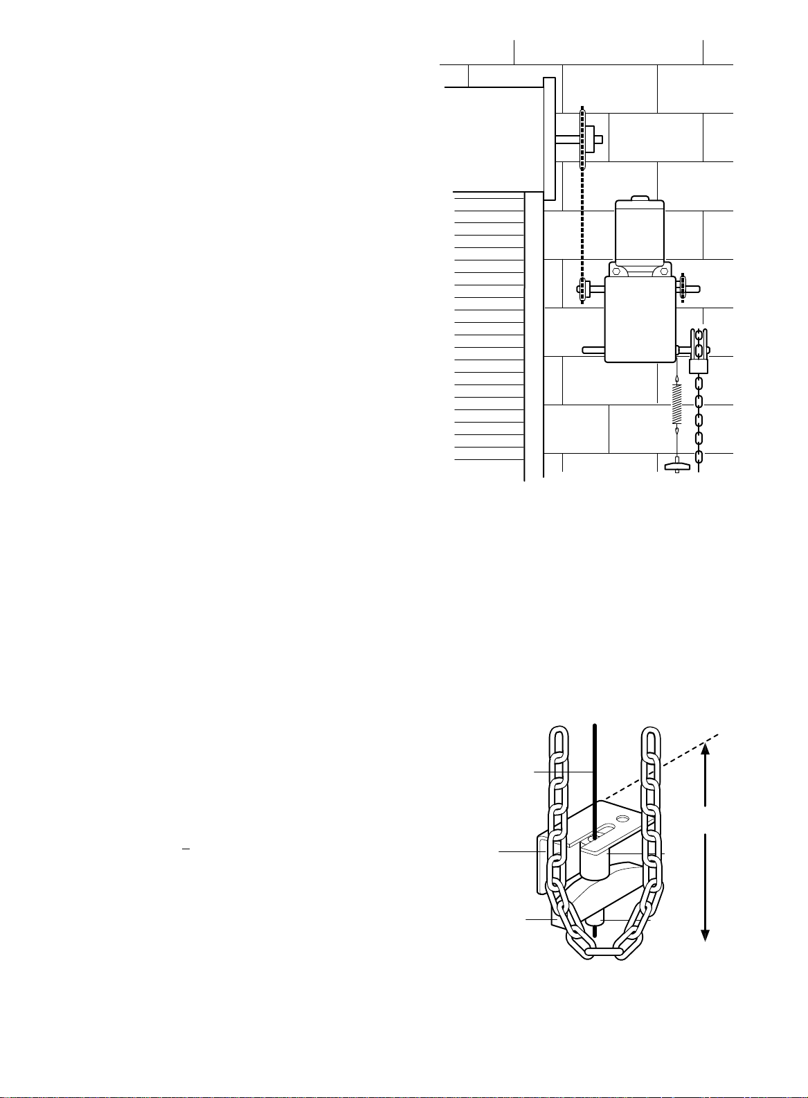
REEL (OPTIONAL)
Take-up reel should be installed 12" above the top of
the door. COIL CORD (OPTIONAL)
Connect operator end of coil cord to junction box (not
supplied) fastened to the wall approximately halfway
up the door opening.
Electrician must hardwire the junction box to the
operator electrical box in accordance with local
codes.
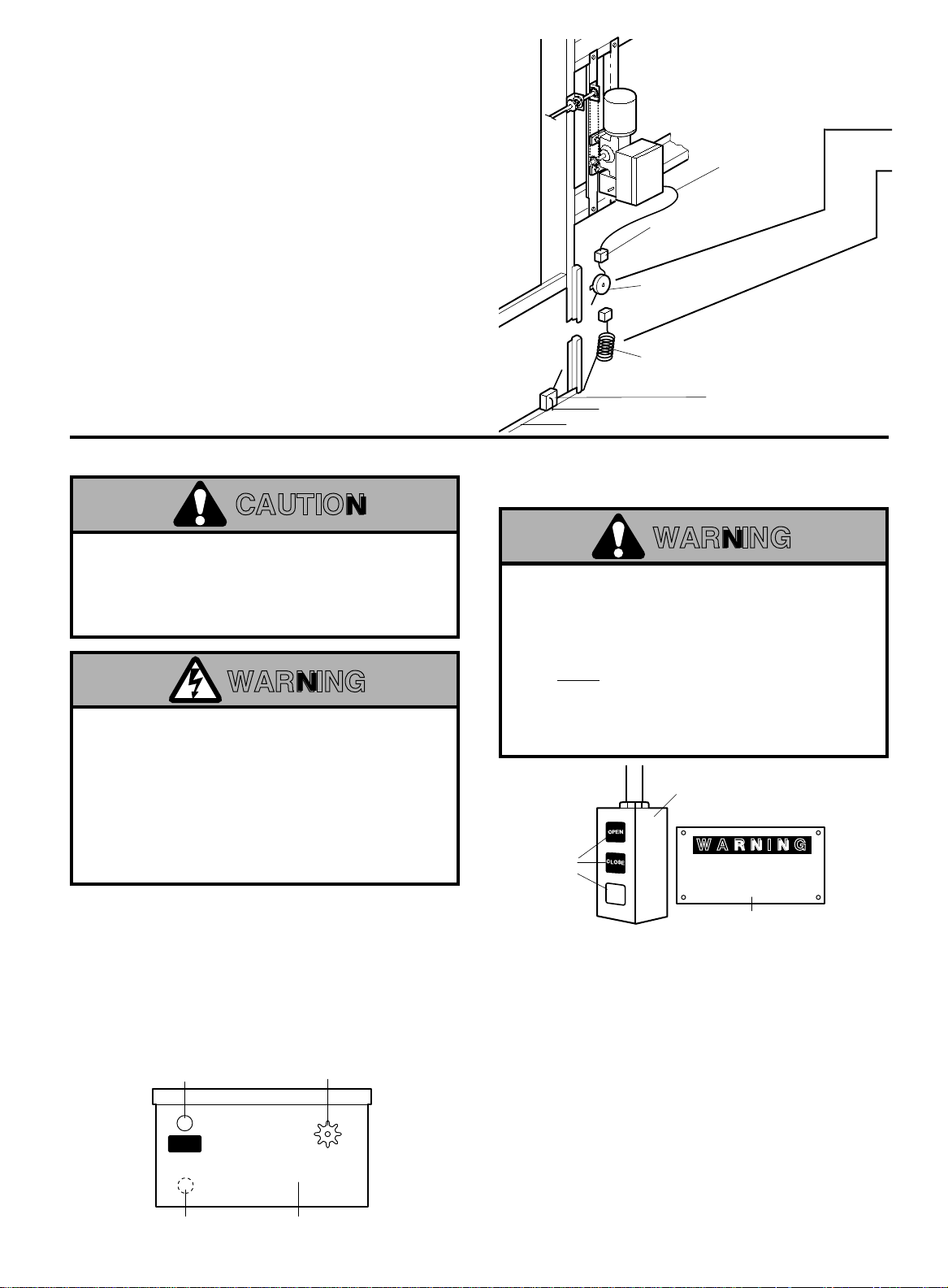
13. Complete electrical connections to the operator
and the control station. Fasten the control station
to the wall and MOUNT THE WARNING NOTICE
BESIDE OR BELOW THE PUSH BUTTONS.
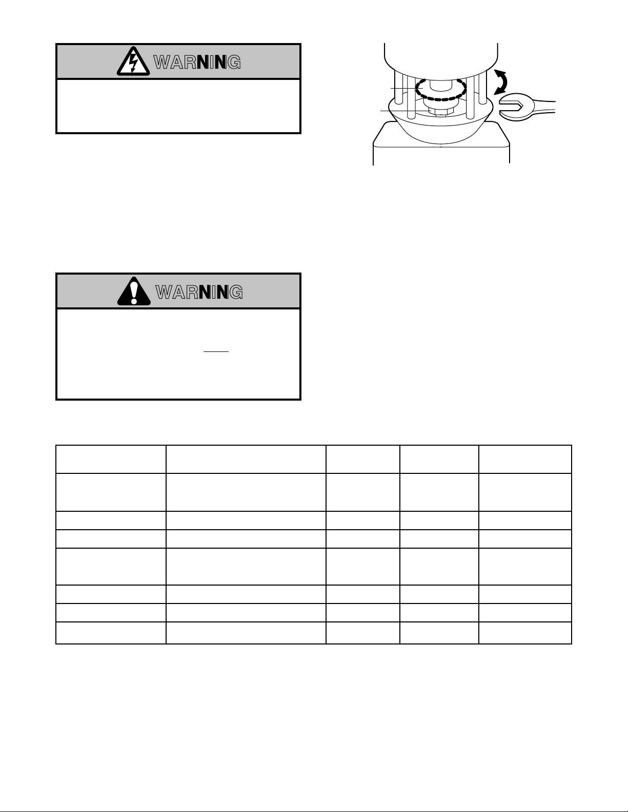
14. Apply power to the operator. Press OPEN push
button and observe direction of output shaft
rotation. See Figure 3, page 3. Press the STOP
button.
If shaft does not rotate in the correct direction,
check for improper wiring at the control station or
between operator and control station.
If the operator is three phase and control station
wiring is correct, exchange any two of the three
incoming power leads.
If electrical problems persist, call our Toll Free
number for assistance (1-800-528-6563).
Installation of Operator
to Sectional Door
(Metal Building)
Make-up Box
(Not Provided)
Take-up Reel
(Optional)
Coil Cord
(Optional) Pneumatic Air Switch:
Not required or supplied
when electric sensing
edge is used
Air Hose
Reversing Edge
Wire (24V)
7/8" Hole for CONTROL
(LOW Voltage) Wires
Hole for POWER
(HIGH Voltage) Wires
Sprocket
CONTROL
WIRING
Electrical Box
WARNING
TO PREVENT ENTRAPMENT
DO NOT START DOOR DOWNWARD
UNLESS DOORWAY IS CLEAR
OPEN
CLOSE
STOP
Standard
Control Station
WARNING Notice
Push
Buttons
WARNING
INSTALL THE CONTROL STATION WHERE THE
DOOR IS VISIBLE, BUT AWAY FROM THE DOOR AND
ITS HARDWARE. IF CONTROL STATION CANNOT BE
INSTALLED WHERE DOOR IS VISIBLE, OR IF ANY
DEVICE OTHER THAN THE CONTROL STATION IS
USED TO ACTIVATE THE DOOR,
A REVERSING
EDGE MUST BE INSTALLED ON THE BOTTOM OF
THE DOOR.
FAILURE TO INSTALL A REVERSING
EDGE UNDER THESE CIRCUMSTANCES MAY
RESULT IN SERIOUS PERSONAL INJURY OR DEATH
TO PERSONS TRAPPED BENEATH THE DOOR.
CABLE CONNECTION NOTE
Be sure to use the control box opening with the 1-
1/16" hole for the POWER cable. All control wires use
the 7/8" hole.
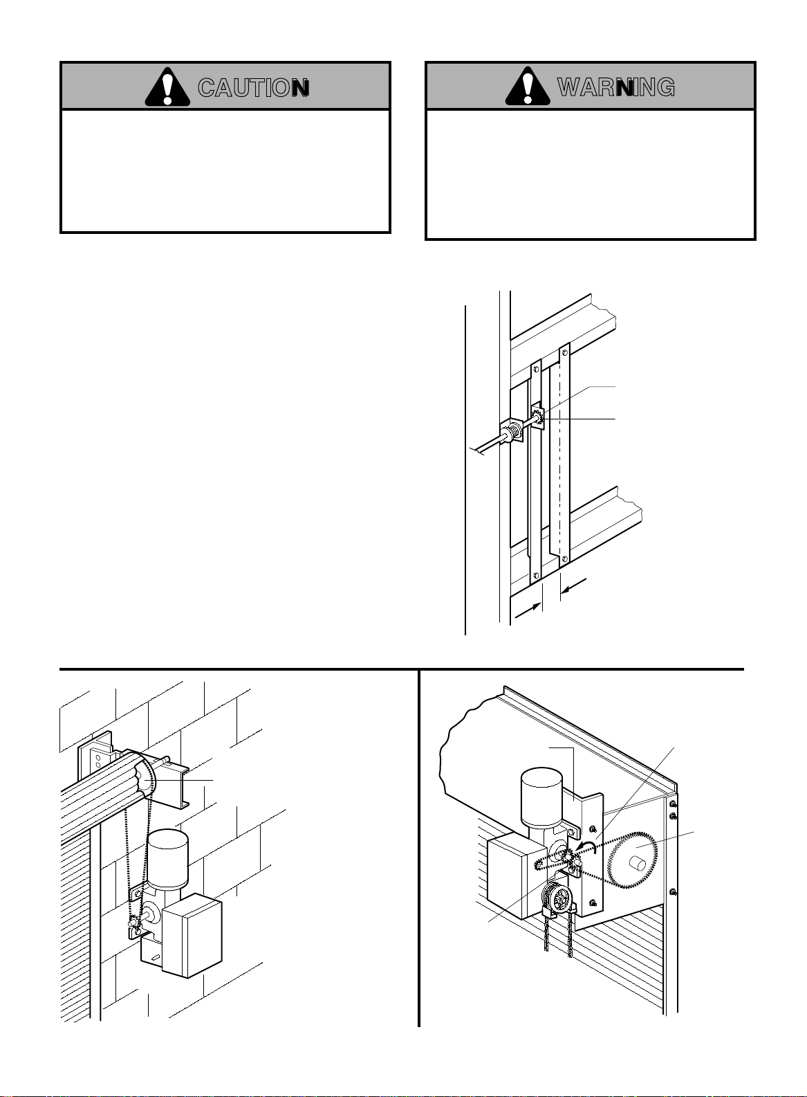
WARNING
DISCONNECT POWER TO THE FUSE BOX BEFORE
PROCEEDING.
OPERATOR MUST BE PROPERLY GROUNDED AND
CONNECTED IN ACCORDANCE WITH LOCAL
ELECTRICAL CODES. THE OPERATOR SHOULD BE
ON A SEPARATE FUSED LINE OF ADEQUATE
CAPACITY.
ALL ELECTRICAL CONNECTIONS MUST BE MADE
BY A QUALIFIED INDIVIDUAL.
CAUTION
TO AVOID DAMAGE TO DOOR AND OPERATOR,
MAKE ALL DOOR LOCKS INOPERATIVE. SECURE
LOCK(S) IN "OPEN" POSITION.
IF THE DOOR LOCK NEEDS TO REMAIN
FUNCTIONAL, INSTALL AN INTERLOCK SWITCH.
FIGURE 7
Refer to Master Wiring Diagram. Make connection
through holes labeled for power and control. Do
not run control wires in the same conduit as
power wires.
INSTALL CONTROL STATION
Install the optional Reversing Edge before
proceeding with the Control Station Installation.