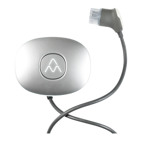
Charge Amps Halo Wallbox User manual

CHARGE AMPS
Halo Wallbox for InCharge
Installation manual
Halo Wallbox 3.7 kW, 7.4 kW and 11 kW

CHARGE AMPS Installation manual for Halo Wallbox for InCharge | © 2020 Charge Amps AB 1
Frösundaleden 4B 130040, rev 01
169 75 Solna Sweden
www.chargeamps.com
Contents
Greetings installer!................................................................................................................................... 2
Safety precautions................................................................................................................................... 2
About Halo ............................................................................................................................................... 3
Model overview........................................................................................................................................ 3
Contents of the package.......................................................................................................................... 4
Provided by the installer ...................................................................................................................... 4
Before installation .................................................................................................................................... 4
Tools .................................................................................................................................................... 4
Cabling................................................................................................................................................. 5
Mounting .............................................................................................................................................. 5
Connection........................................................................................................................................... 5
Installing the Halo .................................................................................................................................... 5
Install and mount the Halo as follows:................................................................................................. 5
Configuring electrical parameters for Halo .............................................................................................. 8
Installation................................................................................................................................................ 8
OCPP (certain models only) .................................................................................................................... 8
Settings.................................................................................................................................................... 8
Status indications on Halo ....................................................................................................................... 8
Halo error indications............................................................................................................................... 9
Rights....................................................................................................................................................... 9
Drill Template appendix......................................................................................................................... 10

CHARGE AMPS Installation manual for Halo Wallbox for InCharge | © 2020 Charge Amps AB 2
Frösundaleden 4B 130040, rev 01
169 75 Solna Sweden
www.chargeamps.com
Greetings installer!
This installation manual is intended for qualified Halo Wallbox installers and describes how to install
the product safely and properly.
Installation may only be carried out by a qualified installer who follows:
•Basic safety precautions for safe and correct installation.
•Local, regional and national installation regulations.
•The instructions in this Halo Wallbox installation manual.
Safety precautions
The installation manual contains important instructions for how to install the product. In addition to the
instructions in this manual, basic safety precautions, including all applicable local, regional and national
laws and regulations, must be complied with when installing, repairing and maintaining the product.
The installation manual also contains safety instructions (WARNING, CAUTION and NOTE) for how to install
the product safely. See the definitions below.
WARNING! – Indicates a potentially dangerous situation that could lead to serious injury or
death.
CAUTION! – Indicates a potentially dangerous situation that could lead to minor or
moderate injury.
NOTE! – Indicates that you must follow the instructions to avoid damaging the product or
other equipment.

CHARGE AMPS Installation manual for Halo Wallbox for InCharge | © 2020 Charge Amps AB 3
Frösundaleden 4B 130040, rev 01
169 75 Solna Sweden
www.chargeamps.com
About Halo
Halo is compatible with all rechargeable electric vehicles. Halo comes with a type 2 charging
connector but can easily be configured for type 1 cars through exchange of the charging cable
(accessory).
Halo is designed in Sweden and meets the requirements of the IEC 61851-1 and IEC 62196-2
standards. The enclosure is made of recycled aluminium, and the product meets the requirements of
enclosure rating IP 66 when properly installed.
Contact your supplier for more information about your specific Halo.
Model overview
1. Aluminium front assembly (Opened only by a qualified installer during installation)
2. Centre cover: LED indication, RFID detection (if activated)
3. Plug
4. LED ring
5. Aluminium rear assembly: mounted on the wall by the installer
6. LED lighting
7. Charging cable entry: fixed charging cable
8. Plastic Membrane
9. Cable entry: incoming electrical connection
10. Cable entry: LAN connection

CHARGE AMPS Installation manual for Halo Wallbox for InCharge | © 2020 Charge Amps AB 4
Frösundaleden 4B 130040, rev 01
169 75 Solna Sweden
www.chargeamps.com
Contents of the package
•Halo
•Five-pin terminal connector for feed current
•Wall holder for charging cable
Provided by the installer
•Three 5 mm screws with associated plugs (if required) for mounting the Halo. The screws
must have a flat head and be suitable for the wall material.
•External sealant for the wall (if necessary), depending on the structure of the mounting wall
•External type A RCD, 30 mA
•Installation cable, according to the charging capability of the selected product
•Four 3.5 mm screws with recessed head for wall mounting of the charging cable connector
•LAN cable
The installer also provides the tools required for installation.
Before installation
Make sure that the right conditions and materials are in place before installation. The installation must
be done in accordance with the instructions in this installation manual as well as basic safety
precautions.
Tools
The following tools are needed for installation:
•Screwdriver, flat electric screwdriver 3.5 mm
•Drill for screw/plug for wall mount
•Laser/spirit level for proper mounting on the wall
•Wire stripper for cabling
•Angled Allen key H4
•Sealant (if necessary) if the wall for mounting is uneven and exposed to an outdoor climate

CHARGE AMPS Installation manual for Halo Wallbox for InCharge | © 2020 Charge Amps AB 5
Frösundaleden 4B 130040, rev 01
169 75 Solna Sweden
www.chargeamps.com
Cabling and Fuse
Check the following before installing the Halo:
•The power is switched off
•The incoming cabling is dimensioned to be able to connect the Halo
oMinimum 2.5 mm2for 16 A
(electrical conditions in the facility and cable lengths may require a higher cross-
sectional area to meet the triggering conditions)
oMinimum 6 mm2for 32 A
(electrical conditions in the facility and cable lengths may require a higher cross-
sectional area to meet the triggering conditions)
•The product is properly fused – 16 A (C or B Curve MCB)* 1-phase 3.7 kW; 16 A (C or B
Curve MCB)* 3-phase 11 kW; 32 A (B Curve MCB)* 1-phase 7.4 kW
•An RCD Type A is installed solely for Halo
* MCB = Miniature Circuit Breaker, B Curve MCB’s trip at 3-5 times rated current and
C Curve MCB’s trip at 5-10 times rated current.
Mounting
Check the following conditions for mounting:
•That the wall can handle a weight of 5 kg
•That the installation screws and plugs (if required) are suitable for the material of the wall
•There is free space at the recommended mounting height (750–1450 mm as measured up to
the bottom edge of the Halo)
•That the position of the Halo does not cause it to be subjected to flammable, explosive,
corrosive or combustible materials, chemicals or fumes
If possible, do not mount the Halo in direct sunlight. The charging current decreases if the temperature
inside the charging station goes up and can even be switched off completely if the Halo gets too hot.
This is a safety feature to ensure a long service life. See the technical specifications for Halo for
operating temperatures.
Connection
To use your Halo, an internet connection is required. Check with your supplier what internet
connection requirements there are for your particular Halo.
Installing the Halo
Install and mount the Halo as follows:
1. Read the installation instructions in this document thoroughly.
2. Make sure that the feed cable is isolated and switch off the power at the main switch.
3. Mount a separate type A RCD on the feed line to the Halo. (The integrated DC protection
against fault currents in the Halo coupled with an external type A RCD has the same
functionality as a type B RCD.)
4. Unpack the Halo from its box. Check that the product is in good condition and that all cables
are properly seated.

CHARGE AMPS Installation manual for Halo Wallbox for InCharge | © 2020 Charge Amps AB 6
Frösundaleden 4B 130040, rev 01
169 75 Solna Sweden
www.chargeamps.com
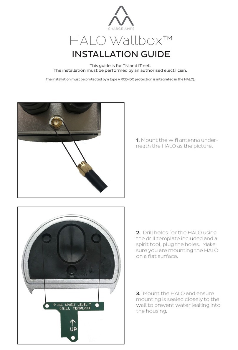
5. Mark the mounting holes on the wall using the provided drill template (see the Drill Template
appendix). Also use a laser or spirit level. For a suitable height, see “Mounting” above.
5. Drill holes with a drill bit designed for the selected fastener.
6. Open the Halo with an H4 Allen key (be careful to make sure that the O-rings securing the
screws do not come loose, the O-rings does not only hold the screws in place they are also
needed to get the Halo watertight).
7. Remove all connected terminal blocks/connectors from the circuit board in the aluminium
cover.
8. Temporarily place the front assembly on a protected surface.
9. Mount the rear assembly on the wall with the selected fasteners. Use sealant if you are
installing in an outdoor environment or on an uneven surface.
10. Strip and insert the electrical cable in the cable entry underneath (15–20 cm is recommended
for easy mounting).
The Halo must be earthed through permanent electrical installation.
Only use the product within the specified operating parameters. Follow local, regional
and national standards and regulations so that no charging current limitations are
exceeded.
Avoid inserting the electrical cable through the plastic membrane. Plastic shrinks and
expands at different temperatures, and water could start to leak in. Enclosure rating
IP 66 only applies if the electrical cable is inserted through the specified cable entry!
11. Tighten the cable entry screw connector tightly.
12. Screw the power supply into the 5-pin terminal block as illustrated below.
a. Connection of 1-phase in TN network
In a 1-phase connection, make the following connections.
b. Connection of 1-phase in IT network

CHARGE AMPS Installation manual for Halo Wallbox for InCharge | © 2020 Charge Amps AB 7
Frösundaleden 4B 130040, rev 01
169 75 Solna Sweden
www.chargeamps.com
c. Connection of 3-phase in TN network (TN network only)
13. Refit the terminals in the front assembly.
1. 5-pin terminal block for incoming power supply
2. Connection for LED lighting
3. 6-pin terminal block for charging cable
4. Not used
5. Ethernet port
The cable ethernet connector must be of short type. Make sure that the connector
and the cable does not interfere with the aluminium rear housing when assembled. If
interference exists, this will break and damage the ethernet port of the Halo.

CHARGE AMPS Installation manual for Halo Wallbox for InCharge | © 2020 Charge Amps AB 8
Frösundaleden 4B 130040, rev 01
169 75 Solna Sweden
www.chargeamps.com
14. Refit the front assembly to the rear assembly. Carefully check that:
a. All O-rings around the fastening screws are in place
b. No cables are pinched
c. The front assembly is mounted the right way, with the InCharge logo facing the right
way.
15. Tighten the four H4 Allen head screws with a torque of 1.5–2.0 Nm.
16. Switch on the power at the main switch/electrical distribution box.
A start-up sequence with self-test begins.
17. Once the Halo is illuminated with a steady white light, the Halo is ready for use.
18. Call Vattenfall Customer service to ensure that Halo is connected to InCharge backend.
Telephone number:
- Norway: 22 73 01 00
- Germany: 0800 – 2 335 335
- Sweden: 020 – 52 62 00
Be careful to refit the front assembly the right way, i.e. with the InCharge logo pointing up. If
the front assembly is fit the wrong way, you risk crushing the circuit board.
Configuring electrical parameters for Halo
The Halo is preconfigured for 16 A available charging current from the installation.
The local management interface is disabled and changes to the available installation current should be
done by contacting Vattenfall Customer service.
Status indications on Halo
Halo uses light to communicate its status in different ways.

CHARGE AMPS Installation manual for Halo Wallbox for InCharge | © 2020 Charge Amps AB 9
Frösundaleden 4B 130040, rev 01
169 75 Solna Sweden
www.chargeamps.com
Indication
Status
The LED ring lights up incrementally in
pace with start-up
The Halo is starting up
The LED ring is illuminated with a steady
white light
The Halo is in standby mode/ready for charging or
charging is complete
The LED ring is illuminated with a steady
white light, but LEDs in the bottom left and
right corners are off
The Halo is in standby mode/ready for charging or
charging is complete
The LED ring’s white light rotates, and the
centre cover is blue
Charging in progress
The centre cover flashes blue and the LED
ring is illuminated with a steady white light
For Halo with RFID only
Waiting for identification with RFID tag on centre cover
(if RFID is activated)
The centre cover is illuminated red for 3
seconds and the LED ring is illuminated
with a steady white light
For Halo with RFID only
The RFID tag is not approved (if RFID is activated),
charging is not activated
Halo error indications
Halo uses light to communicate its status in different ways.
Indication
Type of error
Action
The LED ring is not
illuminated white
and the centre
cover is illuminated
red
An error has occurred that
affects the Halo. It could be
an error in the vehicle or an
earth fault that occurred
during electrical installation.
Check that the charging cable is intact, cut off
power to the Halo via the main switch, and
restart the Halo after a few minutes. If this does
not work, see “Product support and service for
Halo” in the Halo user manual.
If none of these actions remedy the problem, contact the supplier for support.
Rights
The information in this document has been checked for accuracy. Charge Amps AB reserves the right
to make technical changes and changes to the contents of the document without prior notice. Charge
Amps AB can not guarantee that all of the content of this particular document is accurate, up-to-date,
and free from printing and proofreading errors. Moreover, Charge Amps AB cannot be held liable for
any mistakes, near-misses, injuries/damage or incidents – direct or indirect – that can be linked to the
use of the safety precautions or products in this document.

CHARGE AMPS Installation manual for Halo Wallbox for InCharge | © 2020 Charge Amps AB 10
Frösundaleden 4B 130040, rev 01
169 75 Solna Sweden
www.chargeamps.com
Charge Amps AB reserves all rights to this document, as well as the information and illustrations
therein. It is strictly forbidden to – in whole or in part – copy, adapt or translate the information without
prior written permission from Charge Amps AB.
© Copyright 2020, Charge Amps AB. All rights reserved.
Drill Template appendix
Place the drill template on the wall and drill using its hole pattern. Before drilling, perform a check
measurement to ensure the measurements between the holes are correct.
Other manuals for Halo Wallbox
2
Table of contents
Other Charge Amps Batteries Charger manuals

Charge Amps
Charge Amps Aura User manual

Charge Amps
Charge Amps Halo Wallbox User manual

Charge Amps
Charge Amps Halo User manual

Charge Amps
Charge Amps Halo User manual

Charge Amps
Charge Amps Aura User manual

Charge Amps
Charge Amps Aura User manual

Charge Amps
Charge Amps Halo Wallbox Operating manual

Charge Amps
Charge Amps Halo User manual

Charge Amps
Charge Amps Aura User manual

Charge Amps
Charge Amps Aura User manual