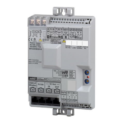
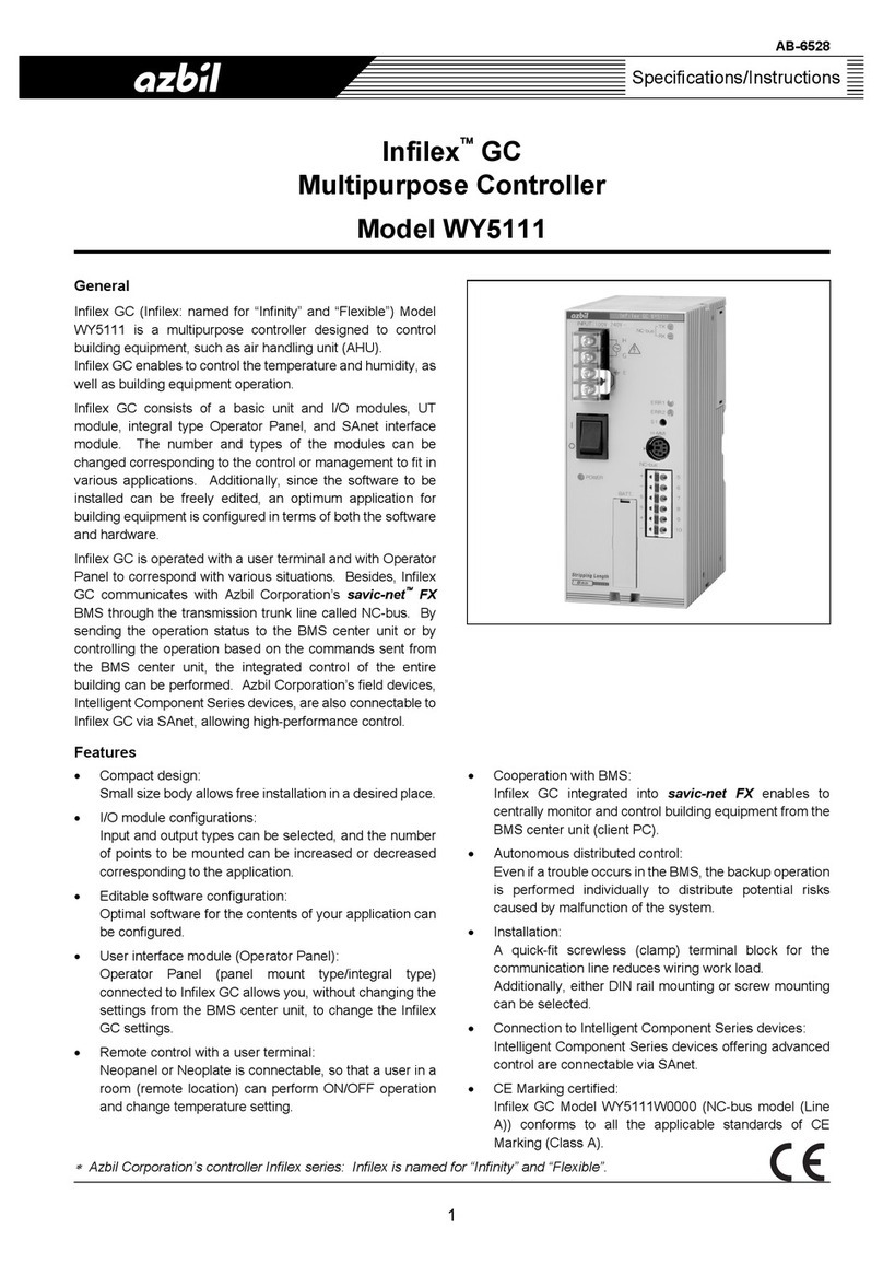
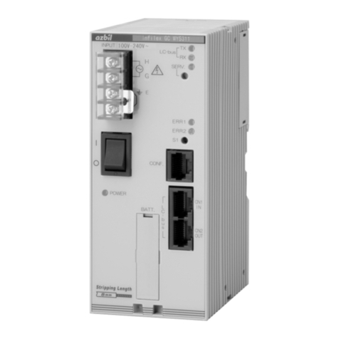
Azbil Infilex BC WY5610 User manual

AB-7163
Our controller Infilex series: Infilex is named for “Infinity” and “Flexible”.
1
Specifications/Instructions
Infilex™BC
Multipurpose Controller
I/O Control Unit
General
Infilex BC (Infilex: named for “Infinity” and “Flexible”) Model
WY5610 is a multipurpose controller designed to control
building equipment, such as air handling unit (AHU).
Infilex BC enables to control the temperature and humidity,
as well as building equipment operations.
Infilex BC consists of the control unit, the I/O control unit, and
I/O modules. The number and types of the I/O modules can
be changed corresponding to the control or management to
fit various applications. Additionally, since the software to be
installed can be freely edited, an optimum application for
building equipment is configured in terms of both the
software and hardware.
Infilex BC communicates with our savic-net™ FX BMS
(Building Management System) through BACnet®/IP
network. By sending the operation status to the BMS center
unit or by controlling the operations based on the commands
sent from the BMS center unit, the integrated control of the
entire building can be performed.
Features
●BACnet® controller:
Infilex BC is integrated in the BACnet/IP network.
●Compact design:
Small size body allows free installation in a desired
place.
●I/O module configurations:
Input and output types are selectable, and the number of
points to mount can be increased or decreased
corresponding to your application.
●Software configuration:
Software is editable to fit for the contents of your
application.
●User interface module (Operator Panel):
Operator Panel (panel mount type/integral type)
connected to Infilex BC I/O control unit allows you,
without changing the settings from the BMS center unit,
to change the Infilex BC settings.
●Remote control with a user terminal:
Neopanel or Neoplate is connectable, so that a user in a
room (remote location) can turn ON and OFF the AHU
and change temperature setting.
●Cooperation with BMS:
Infilex BC integrated into savic-net FX BMS enables to
centrally monitor and control building equipment from the
BMS center unit (client PC).
●Autonomous distributed control:
Even if a trouble occurs in the BMS, the backup
operation is performed individually to distribute potential
risks caused by malfunction of the system.
●Easy wiring:
Screwless push-in terminals for the communication line
reduces wiring work load.
●CE Marking certified:
Infilex BC I/O control unit Model WY5611W0000
conforms to all the applicable standards of CE Marking
(Class A).

AB-7163
2
Safety Instructions
Please read instructions carefully and use the product as specified in this manual. Be sure to keep this manual near by for ready
reference.
Restrictions
This product is targeted for general air conditioning. Do not use this product in a situation where human life may be affected. If
this product is used in a clean room or a place where reliability or control accuracy is particularly required, please contact our
sales representative. Azbil Corporation will not bear any responsibility for the results produced by the operators.
Warnings and Cautions
WARNING Alerts users that improper handling may cause death or serious injury.
CAUTION Alerts users that improper handling may cause minor injury or material loss.
Signs
Alerts users possible hazardous conditions caused by erroneous operation or erroneous use. The symbol inside
indicates the specific type of danger.
(For example, the sign on the left warns of the risk of electric shock.)
Notifies users that specific actions are prohibited to prevent possible danger. The symbol inside graphically
indicates the prohibited action.
(For example, the sign on the left notifies that disassembly is prohibited.)
Instructs users to carry out a specific obligatory action to prevent possible danger. The symbol inside graphically
indicates the actual action to be carried out.
(For example, the sign on the left indicates general instructions.)
WARNING
Before wiring, be sure to turn off the power to the product.
Failure to do so might cause electric shock.
Be sure to ground the product with ground resistance of less than 100 Ω.
Improper grounding might cause electric shock or malfunction.
Detach the terminal cover only when wiring the product. Before detaching the terminal cover, be sure to turn off the
power to the product and all the connected devices. After wiring, be sure to reattach the terminal cover.
Failure to do so might cause electric shock.
Before replacing the unit, be sure to turn off the power to the unit.
Failure to do so might cause electric shock.
Install this product in a location out of reach of unauthorized people. (e.g. Inside of the control panel)
Failure to do so might cause electric shock.
CAUTION (1/2)
Use the product under the operating conditions (temperature, humidity, power, vibration, shock, mounting direction,
atmospheric condition, etc.) as listed in the specifications.
Failure to do so might cause fire or device failure.
Use the product within the rated operating ranges as listed in the specifications.
Failure to do so might cause device failure.
Installation and wiring must be performed by qualified personnel in accordance with all applicable safety standards.
All wiring must comply with applicable codes and ordinances.
Take anti-lightening measures based on regional and building characteristics.
Lightening might cause fire or critical damage to the products without the anti-lightening measures.
Take anti-noise measures if the product is installed in a location near electric noise sources.
Failure to do so might cause malfunction or device failure.

AB-7163
3
CAUTION (2/2)
Connect the cables to the product power supply terminals with the terminal lugs or an equivalent method to assure
permanent connection.
To connect the wires to the screw terminals, use crimp terminal lugs with insulation.
Failure to do so might cause short circuit or electric shock.
Firmly tighten the terminal screws.
Insufficient tightening of the terminal screws might cause overheating or fire (or inaccurate measurement).
To connect the wires to the screwless push-in terminals, strip 8 mm of the wire insulation. If the strip length is longer
than the specified, the stripped part of the wires will be exposed, causing electric shock or short circuit between
adjacent terminals. If the length is shorter than the specified, the stripped part will not contact the connector.
Do not block the ventilation holes of this product. (Be sure to peel off the protective sheet after installation and wiring).
Doing so might cause fire or device failure.
After mounting the modules on DIN rail, push up the DIN rail holders of the modules to secure them on the DIN rail.
If the modules are not fixed with the DIN rail holder, they might drop from the DIN rail and get damaged.
If more than the rated power voltage is applied to the product, replace the product with new one for your safety.
Failure to do so might cause device failure or overheating.
Do not disassemble the product.
Doing so might cause electric shock or device failure.
Dispose of the used batteries in accordance with your local regulations. Do not throw them in fire or in general
garbage.
Doing so might cause burst or ignition.
Dispose of the product as industrial waste in accordance with your local regulations.
Do not reuse all or part of this product.

AB-7163
4
System Configuration
Infilex™ BC (Models WY5610W0010 and WY5611W0000) integrated into BMS: savic-net™ FX*1
Notes:
*1 Fig. 1 shows an example of Infilex BC integrated into savic-net FX BMS. Ask our salesperson for applicable BMS.
*2 MIS may be used instead of SMS and DSS for your system. Note that MIS cannot be mixed with SMS or DSS in the same system.
Figure 1. System configuration example: Infilex BC (Models WY5610W0010 and WY5611W0000) integrated into savic-net FX BMS
Infilex™ BC (Models WY5610W0000 and WY5611W0000) integrated into BMS: savic-net™ FX*1
Notes:
*1 Fig. 2 shows an example of Infilex BC integrated into savic-net FX BMS. Ask our salesperson for applicable BMS.
*2 MIS may be used instead of SMS and DSS for your system. Note that MIS cannot be mixed with SMS or DSS in the same system.
*3 In addition to the I/O modules, UT module and/or integral type Operator Panel may be connected.
Figure 2. System configuration example: Infilex BC (Models WY5610W0000 and WY5611W0000) integrated into savic-net FX BMS
BMS: Building Management System
DSS: Data Storage Server
MIS: Management Integration Server
SCS: System Core Server
SMS: System Management Server
SMS DSS SCS Client PC
Infilex BC
control unit
BACnet
®
/IP
Expansion bus
I/O modules*3
MIS*2
Infilex BC
BACnet
®
router
Third-party
BACnet®device
BACnet
®
MS/TP
Infilex BC
I/O control unit
I/O modules*3
Infilex BC
I/O control unit
Model WY5610W0000
SMS DSS Client PC
Infilex BC
control unit
Infilex BC
I/O control unit
BACnet
®
/IP
Expansion bus
I/O modules
MIS*2
Infilex BC
BACnet
®
router
BACnet
®
MS/TP
BMS: Building Management System
DSS: Data Storage Server
MIS: Management Integration Server
SMS: System Management Server
Infilex BC
I/O control unit I/O modules
BACnet
®
router
BACnet
®
MS/TP
Model WY5610W0010
Third-party
BACnet®device
Infilex VC for
BACnet®MS/TP

AB-7163
5
Model Number
Model number Description
WY5611 Infilex BC I/O control unit
W 100 V AC to 240 V AC power
0000 Fixed.
Notes:
* Infilex BC control unit is always bundled with Infilex BC I/O control unit. When ordering Infilex BC (control unit and I/O control unit), order
number is required.
* For I/O modules, UT module, and integral type Operator Panel to be combined with Infilex BC I/O control unit Model WY5611, separate
order is required.
* Regarding I/O modules, UT module, and integral type Operator Panel to be combined with Model WY5611, refer to AB-6527
Specifications/Instructions of Model RY50XX.
Order Number of Infilex BC
Model WY5610W0010 (control unit) and Model WY5611W0000 (I/O control unit)
Order number Description
83171682 Infilex BC
-
101 One control unit and one I/O control unit
103 One control unit and three I/O control units
105 One control unit and five I/O control units
Model WY5610W0000 (control unit) and Model WY5611W0000 (I/O control unit)
Order number Description
83171682 Infilex BC
-
001 One control unit and one I/O control unit
003 One control unit and three I/O control units
005 One control unit and five I/O control units
Part for Installation (Optional)
Part number Description
83104567-001 DIN rail mounting bracket
Note:
* Infilex BC is mounted on DIN rail, and the DIN rail mounting bracket is required. Be sure to separately order the DIN rail mounting bracket.

AB-7163
6
Specifications
Basic specifications
Item Specification
Rated voltage 100 V AC to 240 V AC, 50 Hz/60 Hz
Allowable voltage range 85 V AC to 264 V AC, 50 Hz/60 Hz
Power shutdown detection 80 V AC or less
Power consumption 40 VA
Power supply
Leakage current 1 mA or less
Ambient temperature 0 C to 50 C
Ambient humidity 10 %RH to 90 %RH (Non-condensing)
Altitude 2000 m or lower
Rated operating
conditions
Vibration Max. 3.2 m/s² (at 10 Hz to 150 Hz)
Ambient temperature -20 C to 60 C
Ambient humidity 5 %RH to 95 %RH (Non-condensing)
Vibration for storage Max. 3.2 m/s² (at 10 Hz to 150 Hz)
Environmental
conditions
Transport/storage
conditions
Vibration for transport Max. 9.8 m/s² (at 10 Hz to 150 Hz)
Green LED ON: Power ONPower supply (POWER)
Green LED OFF: Power OFF
Red LED ON: Major failure or system restartMajor failure (ERR1)
Red LED OFF: Normal operation
Red LED ON: Minor failure or system restart
Operation
Minor failure (ERR2)
Red LED OFF: Normal operation
LED indication
Communication Expansion bus Transmit (TX), Receive (RX)
RAM, RTC* Lithium battery backupPower failure backup
Data file Non-volatile memory backup
Transmission system Current transmission
Transmission speed 4800 bps
Transmission distance 500 m
Communications Expansion bus
I/O control units Max. 25 units connectable
Weight 400 g
Material (housing), color Modified PPE, light gray
Power supply, ground M3 screw terminals (7.62 mm pitch between terminals)Terminals connection
Expansion bus communication Screwless push-in terminals
Wiring specifications: I/O control unit
Item Wiring Wiring length Condition
Power supply JIS IV 2.0 mm² or JIS CVV 2.0 mm² or greater
Grounding JIS IV2.0 mm² or JIS CVV2.0 mm² or greater Ground resistance: 100 Ωor lower
Expansion bus JCS IPEV-S 0.9 mm² 500 m
Notes:
* Pin terminals cannot be used.
* JIS: Japanese Industrial Standards
* JCS: Japanese Electric Wire and Cable Makers’ Association
Wiring specifications: I/O modules
Item Wiring Wiring length
Temperature input JIS IV, JIS CVV, KPEV1.25 mm2100 m
Voltage/Current input JIS IV, JIS CVV, KPEV1.25 mm2100 m
Voltage/Current output JIS IV, JIS CVV, KPEV0.9 mm2, 1.25mm2100 m
Modutrol Motor output JIS IV, JIS CVV, KPEV1.25 mm2100 m
Digital input JIS IV, JIS CVV, KPEV0.5 mm2, 0.75 mm2, 0.9 mm2, 1.25 mm2100 m
Relay output JIS IV, JIS CVV, KPEV1.25 mm2100 m
Remote control relay output JIS IV, JIS CVV, KPEV1.25 mm2100 m
Notes:
* Since a screwless push-in terminals are provided on I/O modules, the wires are connected only by stripping the sheath.
Sheath stripped length: 8 mm (Pin terminal cannot be used.)
* KPEV is a wiring standard provided by Furukawa Electric Co., Ltd.
Specifications of I/O modules, integral type Operator Panel, and UT module
For the specifications of I/O modules and UT module, refer to Specifications/Instructions of Model RY50XX (AB-6527).
For the specifications of integral type of Operator Panel, refer to Specifications/Instructions of Model RY5001Q/QY5100W
(AB-6546).
AB-7163
7
CE Marking Conformity
This product must be installed in a panel cabinet. Besides, the product in the panel cabinet must be out of reach of unauthorized
people who are not well-trained for electric facilities.
This product complies with the following Electromagnetic Compatibility (EMC) and the Low Voltage Directive (LVD).
EMC: EN61326-1 Class A, Table 2 (For use in an industrial electromagnetic environment)
LVD : EN61010-1 Overvoltage category II
Pollution degree 2
Input/Output and Terminal Arrangement
Figure 3. Input/output and terminal arrangement
100 V AC to 240 V AC
Expansion bus
1
2
3
4
TX IN
TX OUT
(+)
(-)
Shield
Shield
(+)
(-)
5
6
7
8
9
10

AB-7163
8
Dimensions
Figure 4. Dimensions (mm)
60 90
140

AB-7163
9
Parts Identification
Figure 5. Parts identification
Table 1. Indication and operation of operating status LED
LED indication LED operation
Data transmitting Expansion bus TX LED: flashing
Data receiving Expansion bus RX LED: flashing
Major failure / system restart ERR1: ON
Minor failure / system restart ERR2: ON
Connection of Data Setter (H-MMI) / PC-MMI
Connection of Data Setter Model QY5111B:
No conversion cable is required. Directly insert the male connector of the Data Setter into the female connector provided on the
Infilex BC I/O control unit.
At this time, hold the male connector with the ◄mark facing left and insert it as the mark points to the ►mark on the
Infilex BC I/O control unit.
Connection of Data Setter Model QY7211B / PC-MMI:
Convert the D-SUB connector to the mini DIN connector with the conversion cable (Part No. 83104995-001).
At this time, hold the male connector with the ◄mark facing left and insert it as the mark points to the ►mark on the
Infilex BC I/O control unit.
Figure 6. Connecting Data Setter/PC-MMI
Insert the male connector as
the two arrows point to each
other.
DIN rail
mounting
hook
Do not press the S1 switch.
S1 switch*
Connector (female)
for Data Setter
Power switch
LED fo
r
Power ON/OFF
Battery holde
r
LED for
operating status

AB-7163
10
Mounting Dimensions
The following figure shows the mounting dimensions of Infilex BC I/O control unit assembled with the modules (I/O modules, UT
module, and/or integral type Operator Panel) on the DIN rail.
Mount and fix Infilex BC I/O control unit assembled with the modules onto the DIN rail so that they do not fall from the DIN rail.
Check that the DIN rail holders of each module are pushed up and fixed on the DIN rail.
Fasten the bilateral sides of Infilex BC I/O control unit assembled with the modules with two DIN rail mounting brackets (Part No.
83104567-001, optional).
Notes:
1 Pitch between upper/lower duct and DIN rail.
2 Hatched area shows the maintenance space.
3 ‘n’ indicates the number of I/O module, UT module, and/or integral type Operator Panel assembled with Infilex BC I/O control unit.
4 DIN rail position is shifted 5 mm downward from the center of Infilex BC I/O control unit.
The width of Infilex BC I/O control unit with the modules varies depending on the number
of the modules (I/O modules, UT module, and/or integral type Operator Panel) to be
assembled.
Width of Infilex BC I/O control unit
= One module (30 mm) n (quantity) + Infilex BC I/O control unit (60 mm)
Notes:
Panel mount type Operator Panel is not directly assembled with Infilex BC I/O control unit. To
connect it to Infilex BC, a UT module is required.
For details of panel mount type Operator Panel, please refer to Specifications/Instructions of
Model RY5001Q/QY5100W (AB-6546).
For details of I/O modules, UT module, and integral type Operator Panel that can be assembled
with Infilex BC I/O control unit, refer to Specifications/Instructions of Model RY50XX
(AB-6527).
I/O module (mm)
Figure 7. Mounting dimensions: DIN rail mounting (mm)
DIN rail mounting brackets for bilateral sides
Part No. 83104567-001
Duct
Duct
Infilex BC
I/O control unit
(
45
)
35
140 (45)
(122.5)*1(132.5)*1
Duct
20
50 92
(60)
(60)
Duct
65 75
35
2
DIN rail holder
Infilex BC
I/O control
unit
DIN rail
Infilex BC
I/O control
unit
60 + 30 n*3
Hook
I/O modules, UT
module, integral type
Operator Panel
5*4
106
30

AB-7163
11
Wiring
Wiring to the power supply terminals
Crimp the M3 terminal lugs to the wire ends, and connect
them to the M3 screw terminals.
Wiring to I/O modules and expansion bus terminals
Since screwless push-in terminals are adopted for the I/O
modules and the expansion bus terminals, the procedure for
connection is specified as follows.
1) Strip the wire sheath 8 mm. (The gauge for the strip
length is located at the front lower part of Infilex BC I/O
control unit. If the stripped part is longer than 8 mm, the
conductor will be exposed, causing electrical shock or
short circuit between adjacent terminals. If it is shorter,
the conductor may not contact the connector.)
2) Make sure that no wire fiber is protruded from the
conductor (stripped wire).
3) Press the clamp release button on the terminals deeply
enough to insert the wire using a slotted screwdriver.
(Maximum button-pressing force is 14 N.)
4) Release the button, and gently pull out the wire
horizontally to make sure that it is tightly fastened. (If you
pull out the wire diagonally, it may be disconnected.)
Make sure that no wire fiber is protruded from the
conductor (stripped conductor).
Positions for connected wires
Neatly place the wires, using cable ties or the like, connected
to Infilex BC I/O control unit so as not to hide LED, Data
Setter connector, ►mark, S1 switch, battery holder, or
indication tag, as shown in Fig. 8.
Make sure there is no slack in the wires from the cable ducts
to Infilex BC I/O control unit.
Figure 8. Connected wires in position (example)
Tube marker
Since Infilex BC I/O control unit adopts a screwless push-in
terminals, wires are connected without crimp terminals.
Therefore, if normal tube markers are used, they may come
off when the wires are disconnected. To prevent this, use the
following Flat Tube Marker. It is held on a wire by friction and
thus does not come off easily.
Manufacturer Phoenix Contact
Part name Flat Tube Marker
Part number 5880029
Model TMC-3
Applicable wire size 0.4 mm2to 2 mm2
Package unit 200 m/roll
System indication label for the controller number
The indication tag has the system indication label on its back.
Turn it over and fill in the controller number on the label.
Figure 9. System indication label
Protective sheet
After connecting the wires, be sure to peel off the protective
sheet before turning on the power.
1) Adhesive is applied to the sheet approximately 20 mm
from the front edge. Peel off this area.
2) Tear off the sheet along the perforations.
Figure 10. Protective sheet
2) Tear off.
1) Peel off the adhesive area.
Indication tag
Turn over.
S1 switch
Connector for
Data Setter
LED
Power switch
LED
Battery holde
r
Indication tag

AB-7163
12
Maintenance (Lithium Battery Replacement)
Replace the lithium battery for backup every five years.
See the following for the battery part numbers.
• One battery per package: Part No. 83170639-001
• Five batteries per package: Part No. 83170639-005
• Ten batteries per package: Part No. 83170639-010
IMPORTANT:
Since the remaining battery capacity cannot be checked by measuring the terminal voltage, be sure to replace
the battery every five years.
Only authorized service personnel is allowed to replace the battery.
Do not touch the power supply unit when replaceing the battery.
Replace the lithium battery every five years if the product is always in use (in ON state).
Replace the lithium battery with the power ON.
If the product has never or hardly been operated (in OFF state) for a year, replace the lithium battery before the
product operation.
Battery replacement
Replace the lithium battery while Infilex BC I/O control unit is ON.
Figure 11. Battery replacement
1) Pull out the battery holder using a slotted screwdriver.
2) Disconnect the connector and detach the lithium battery from the battery holder.
3) Place a new lithium battery in the battery holder and connect the connector to it.
4) Insert the battery holder into the basic unit.
5) Fill in the month and year for next replacement (five years after the replacement) on the indication tag using an oil-based
pen.
1)
4)
5)
3)
2)
Infilex BC
I/O control unit
Lithium battery for backup
Battery holder Battery Connector

AB-7163
13
Precautions for Use
Do not mount the product under the conditions of high temperature and humidity.
Do not drop the product.
For the wire replacement, be sure to turn off the power to the product. (Disconnect the wiring between the power supply and
the product power terminals.)
Before turning on the power, make sure that the wires are correctly connected.
Several tens of seconds are required for the product normal operation after the power is turned on. During this time, the red
LED “ERR1” (major failure) on the front lights up indicating major failure temporarily, but this does not indicate an error.
Do not connect wires to vacant terminals.
Leave at least 35 mm clearance between the top/bottom surfaces of the product and other devices.
Peel off the protective sheet on the top surface of the product before turning ON the power.
(See Figs. 10 and 12.)
Figure 12. Batter label and protective sheet
Protective sheet
Battery label

AB-7163
14
Blank page added for editing purpose.

AB-7163
15
Blank page added for editing purpose.

AB-7163
Infilex and savic-net are trademarks of Azbil Corporation in Japan or in other countries.
BACnet is a registered trademark of American Society of Heating, Refrigerating and Air-Conditioning Engineers (ASHRAE).
KPEV is a registered trademark of Furukawa Electric Co., Ltd. in Japan.
Specifications are subject to change without notice.
Building Systems Company
http://www.azbil.com/
Rev. 2.0 Sep. 2015 AB-7163
16
Table of contents
Other Azbil Controllers manuals

Azbil
Azbil Infilex WY5317C User manual

Azbil
Azbil DMC10E User manual

Azbil
Azbil SDC15 User manual

Azbil
Azbil RA890G User manual

Azbil
Azbil AUR455 User manual

Azbil
Azbil dcp551 mark II User manual

Azbil
Azbil SDC45 User manual

Azbil
Azbil SDC26 Instruction Manual

Azbil
Azbil Infilex VC User manual

Azbil
Azbil Azbil MIZCON Plus User manual