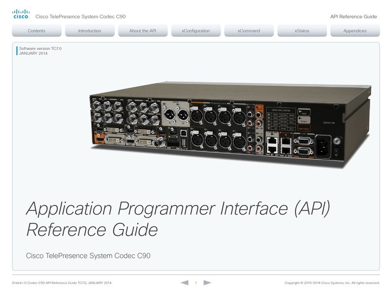
Installing Cisco TelePresence System Codec C90
Page 278-19811-02 Codec C90 Installation Sheet | December 2012 | © 2010-2012 Cisco Systems, Inc. All rights reserved.
4Assembling the rack ear profiles
Mount the left and right rack ear profiles to the codec. 5Mounting the codec onto the rack
Locate the rails and carefully slide the codec onto the rack.
b) Fasten the codec in front
by tightening the screws on
the rack ear profiles.
Video from the camera
(HDMI to HDMI)
PC (audio to
Line In 1 and 2)
LAN/EthernetMicrophoneMain monitor
(audio from HDMI
1 or Line Out 1-2)
Mains power
cable
Loudspeakers
(optional)
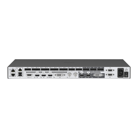
6Connecting cables
Codec C90 offers a great flexibility in connecting audio
and video equipment to the system.
a) Remove the two M3 screws
on the left and right side of the
codec.
Tool: Screwdriver, 2 mm Allen Key
b) Use the same two M3 screws
to fasten the left and right rack ear
profiles to the codec.
a) Locate the rails on the codec and the
rails on the rack. Lift the codec towards
the rack and make sure the codec enter
the rails. Carefully slide the codec into the
rack.
Basic setup - The main connectors are highlighted in orange color.
LEFT
RIGHT
VIDEO INPUT MATRIX
Input Connector type
11st Camera HDMI 1 HD-SDI 1 YPrPb 1
22nd Camera HDMI 2 HD-SDI 2 YPrPb 2
3PC HDMI 3 HD-SDI 3 DVI-I 3
4HDMI 4 HD-SDI 4 —
5DVI-I 5 Comp 5* YC 5*
Audio from PC
Power switch
After having
connected the cables,
you may turn the
codec On.
For a basic setup, you should go through these steps:
1. Connect the main camera to the HDMI 1 input using a
HDMI to HDMI cable.
• For camera control you should also connect the
camera to the Camera Control input using the
dedicated cable that came with your camera (RJ45
to DSUB).
2. Connect the monitor display to the HDMI 1 output using
a HDMI to HDMI cable.
3. If you want to send images from a PC, connect the
PC to the DVI-I 3 input, using a DVI to DVI cable (for
digital signals) or VGA to DVI cable (for analog signals)
depending on your PC’s capabilities.
• Audio from the PC could be connected to Line 1 and
2 inputs for stereo signals.
4. Connect a microphone to the XLR 1 input.
5. If the monitor speakers do not support audio over HDMI,
connect the loudspeakers to the Line 1 and 2 outputs.
6. Connect the codec to the IP network using the
Ethernet 1 interface.
7. Connect the power and use the power switch to turn
the codec on.
NOTE: If using the DVI-I output (2 or 4) or HDMI 3 for the
main monitor a shortcut is required to move the on screen
display (OSD) to this output. On the remote control key in
the following sequence:
• Disconnect – *– #– *– #– 0– 2– # (where 2
represents DVI-I 2)
Only one video source from each row can be active at any
time. Note that the Comp 5 and YC 5 inputs uses the same
physical connectors and can not be connected at the same
time.
* Comp 5 and YC 5 are not active in version 1
INPUTS OUTPUTS Basic setup
The main connectors for basic
setup are highlighted in orange.
Camera control
(RJ45 to DSUB)
1 1
IMPORTANT
There should always be a distance of
minimum 10 cm / 4 in. free space in front
of the codec.
SAFETY REQUIREMENT
Make sure the codec is not mounted with
the front side up or down.
Min. 10 cm
