manuals.online logo
Brands
  1. Home
  2. •
  3. Brands
  4. •
  5. Sony
  6. •
  7. Conference System
  8. •
  9. Sony IPELA PCS-XG55S User manual

Sony IPELA PCS-XG55S User manual

* I - 4179434134 *
4-179-434-13 (1)
HD Visual Communication System PCS-XG80/XG80S/XG55/XG55S/XA80/XA55
Installation Guide
“IPELA” and are trademarks of Sony Corporation.
© 2010 Sony Corporation Printed in Japan
Let’s Connect
Notes
Be sure to turn off all the equipment before making any connections.ˎ
Do not connect/disconnect the camera cable, interface cable, or pen tablet withˎ
the power on. Doing so may damage the Camera Unit, Communication System
or ISDN Unit.
For safety, do not connect the 100BASE-TX/10BASE-T connector to a networkˎ
that applies excess voltage via the 100BASE-TX/10BASE-T connector.
Used with the Camera Unit or ISDN Unit for the first time,ˎthe Communication
System may automatically upgrade the software of the connected equipment.
Upgrade the software according to the message displayed on the monitor
screen. Be sure not to turn off the Communication System or disconnect the
cable during upgrading. Otherwise it may cause a malfunction of the system.
PCSA-CXG80 HD Camera
Unit (supplied with the
PCS-XG80/XG55)1) PCSA-CXA55 HD Camera
Unit (supplied with the
PCS-XA80/XA55)
TV monitor2) 3)
ISDN Unit2)
HDMI cable1)
Interface
cable
(supplied
with the
ISDN Unit)
1) Supplied
(However, the PCSA-CXG80 HD Camera Unit and the PCS-A1 microphones are not supplied with the PCS-XG80S/
XG55S system. The PCS-XG80 is supplied with two PCS-A1 microphones, and the PCS-XG55 is supplied with one.
Microphones are not supplied with the PCS-XA80 and the PCS-XA55.)
2) Not supplied
3) Must support 1080i.
PCSA-B384S2)
to ISDN 1 - 3
or
PCSA-B768S2)
to ISDN 1 - 6
ISDN modular cable2)
DC 19.5V
Power cord1)
Computer
Projector, etc.
to RGB IN
UTP cable (category 5, straight)2)
Connecting cable with the
D-sub 15 pin connectors2)
Audio cable2)
RGB IN
Connecting cable
with the D-sub 15 pin
connectors2)
RGB
OUT
to
RGB
OUT
VCR, etc.
to S-video
output to audio output
S-video cable2)
AUDIO 1 IN
S VIDEO
IN
EC-MIC(A7)
1/2
MIC(A1/A3)
1(R)/2(L)
Connecting two
microphones enables pick-
up of the sound in stereo.
PCS-A1
Microphones
(supplied with
the PCS-XG80/
XG55)
1)
or
PCSA-A3
Microphones2)
AUDIO 2 INVIDEO IN
YPbPr
Video cable2) Audio
cable2)
to video
output
(YPbPr)
to audio output
HD player, etc.
PCSA-A7 Echo Canceling Microphones
(PCSA-A7P4: 4-piece set)2)
Camera cable (supplied with
the HD Camera Unit)
LAN
Notes
The PCS-XG55/XG55S/XA55 is not equipped with the following connectors:
ˎ
S VIDEO IN, EC-MIC(A7) 1/2, AUDIO 1 IN, EXT 1/2 and 2 (LAN2) connectors
On the PCS-XG55/XG55S/XA55, the TABLET, AUDIO 2 IN, and
ˎ1 connectors are named the OPTION, AUDIO IN, and connectors,
respectively. In addition, the LAN 1 ALERT and LAN 2 ALERT indicators are named the LAN ALERT and ON LINE indicators, respectively.
Normally, connect the UTP cable to the
ˎ1 (LAN1) connector (indicated in green). If the UTP cable is connected to the 2 (LAN2)
connector, some of the functions of your system may be restricted.
For details, refer to the Operating Instructions supplied with the system.
The REC OUT jack is used to make an audio recording of a communication. This is not used during regular communication.
ˎ
ISDN line
Front Rear
to a wall outlet
1
AC adaptor1)
to TERMINAL to HDMI IN
CAMERA
HDMI OUT
to TERMINAL
ISDN UNIT
TABLET
Pen tablet2)
(Wacom )
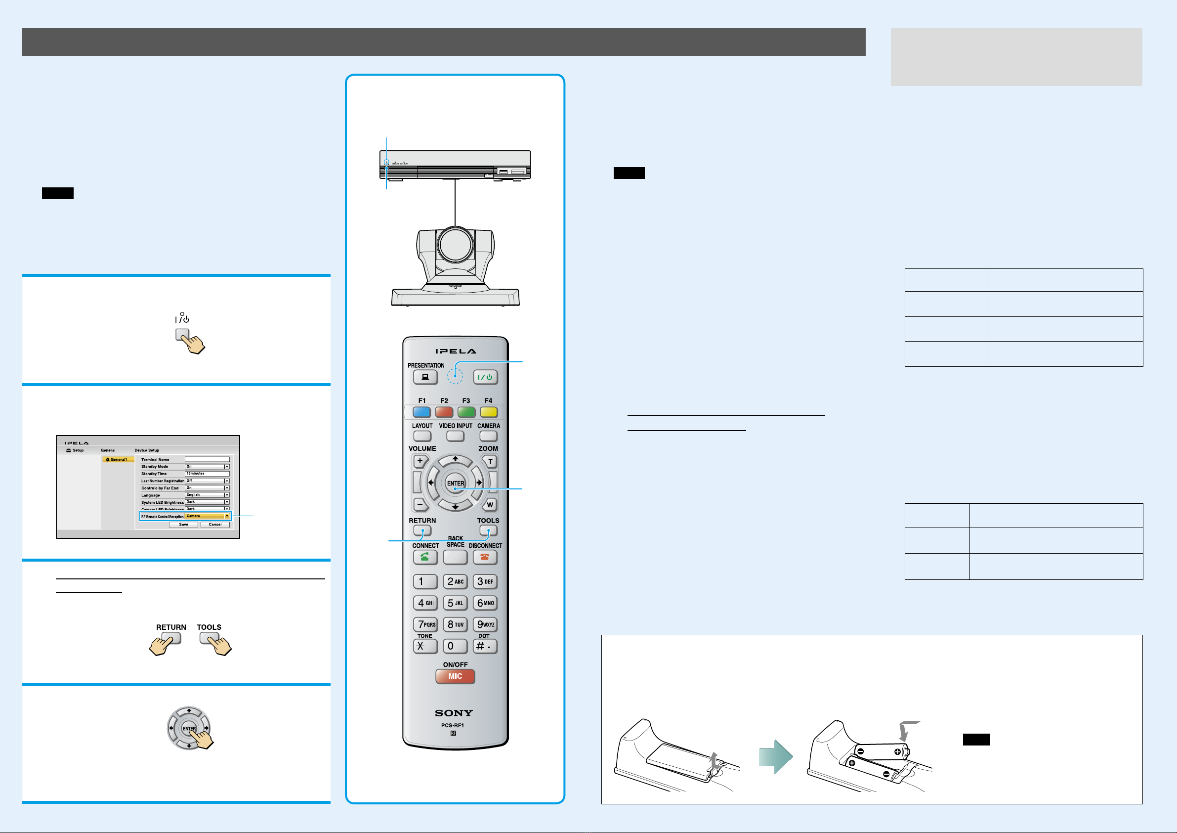
Pairing the Camera Unit with the Remote Commander
1Press the  (power) switch on the
Communication System to turn it on.
The  (power) indicator on the Communication System flashes. The indicator
lights in green when the Communication System turns on.
2Set “RF Remote Control Reception” to “Camera” in
the setup menu of the Communication System and
save the setting.
Set to “Camera.”
For the setting, refer to the Operating Instructions supplied with the System.
3Within three minutes after the power of the System
is turned on, locate the Remote Commander closer
to the RF receiver at the rear of the Camera Unit,
and press “RETURN” and “TOOLS” at the same time.
The Remote Commander and the Camera Unit enter pairing mode, and the LED
indicator on the Remote Commander flashes rapidly.
4Press “ENTER.”
If the LED indicator on the Remote Commander flashes more slowly, pairing the
units has succeeded.
The pairing between the Communication System and the Remote Commander is
disabled.
When pairing has failed
The LED indicator on the Remote Commander continues
flashing rapidly. In this case, press the ENTER button on the
Remote Commander again.
To cancel pairing
Press the  (power) switch on the Communication System.
Notes
When the LED indicator does not flash even if you press any button on
ˎ
the Remote Commander, the batteries might be exhausted. Replace both
batteries with new ones.
Once pairing is established between the units, it will not be erased even if
ˎ
the batteries are replaced.
Operable distance is 10 m (32.8 ft.). Depending on the circumstances, a
ˎ
longer operable distance may be possible.
To pair the Communication System with the
Remote Commander again
Follow the procedure below to release the paring with the
Camera Unit, and to perform pairing with the System again.
Turn on the Communication System.
Set “RF Remote Control Reception” to“System” in
the setup menu of the Communication System.
Within three minutes after the power of
the System is turned on, locate the Remote
Commander closer to the Communication
System, and press “RETURN” and “TOOLS” at the
same time.
The LED indicator flashes rapidly.
Press “ENTER.”
If the LED indicator flashes more slowly, pairing between
the units has succeeded.
1
3
4
 (power) indicator
LED
PCSA-CXG80 HD
Camera Unit
When you change the setting of“Monitor Output” or
“Frequency” on the Video setup menu to an incorrect setting,
no picture will be displayed on the screen. In such a case,
select the correct setting, using the /(power) switch on
the Communication System and the buttons on the Remote
Commander.
To change the “Monitor Output” setting
When the /(power) indicator on the Communication
System stays lit, perform the steps below.
Press the /(power) switch on the Communication
System.
Within five seconds after you pressed the /switch,
press the buttons on the Remote Commander described
below depending on the desired“Monitor Output.”
Desired “Monitor
Output”
On the Remote Commander,
press:
HDMI VIDEO INPUT button (once) 
Number button 3 (three times)
RGB VIDEO INPUT button (once) 
Number button 4 (three times)
HDMI+RGB VIDEO INPUT button (once) 
Number button 5 (three times)
The setting of “Monitor Output” is changed, and the
picture will be displayed on the screen.
To change the “Frequency” setting
When the /(power) indicator on the Communication
System blinks then stays lit after rebooting, perform the steps
below.
Press the /(power) switch on the Communication
System.
Within five seconds after you pressed the /switch,
press the buttons on the Remote Commander described
below depending on the desired“Frequency.”
Desired
“Frequency” On the Remote Commander, press:
60 Hz VIDEO INPUT button (once) Number
button 1 (three times)
50 Hz VIDEO INPUT button (once) Number
button 2 (three times)
The setting of “Frequency” is changed, and the system will
reboot.
The supplied Remote Commander controls the HD Visual
Communication System using the radio frequency of 2.4 GHz. The
Remote Commander and the Communication System are paired to
prevent interference from other Remote Commanders and Systems.
Pairing between the Remote Commander and the Communication
System is programmed at the factory. If the Communication System
is installed in shielded locations, such as under a desk or in a rack, it
may not be controlled by the Remote Commander, depending on the
conditions of radio-wave reception. In this case, pair the PCSA-CXG80
HD Camera Unit with the Remote Commander.
Notes
When performing pairing procedure, be sure to turn off other HD Visualˎ
Communication Systems or HD Camera Units located nearby that are not targets for
pairing. If multiple devices are turned on, the Remote Commander might pair device
other than the target one.
Pairing is not possible with the PCSA-CXA55 HD Camera Unit.ˎ
Changing the “Monitor Output” or
“Frequency” Setting with the Remote
Commander
Inserting batteries into the Remote Commander
1 2 3
Press the battery
compartment lid to
remove the cover.
Insert two size AA (R6)
batteries (supplied) with
correct polarities.
Press the battery compartment
lid to remove the cover.
Note
Be sure to insert the batteries side first. Inserting
them forcibly side first may damage the
nsulated film covering the batteries and cause a
short circuit.

This manual suits for next models

5

Other Sony Conference System manuals

Sony PCS-TL50 User manual

Sony

Sony PCS-TL50 User manual

Sony IPELA PCS-G70 User manual

Sony

Sony IPELA PCS-G70 User manual

Sony PCS-1P Instruction manual

Sony

Sony PCS-1P Instruction manual

Sony PCS-XG100 Instruction Manual

Sony

Sony PCS-XG100 Instruction Manual

Sony Ipela PCS-G70S User manual

Sony

Sony Ipela PCS-G70S User manual

Sony PCSXL55 Instruction Manual

Sony

Sony PCSXL55 Instruction Manual

Sony PCS-11 User manual

Sony

Sony PCS-11 User manual

Sony PCS-1 - Video Conferencing Kit User manual

Sony

Sony PCS-1 - Video Conferencing Kit User manual

Sony PCS-VCS User manual

Sony

Sony PCS-VCS User manual

Sony PCS-1 - Video Conferencing Kit User manual

Sony

Sony PCS-1 - Video Conferencing Kit User manual

Sony IPELA PCS-HG90 User manual

Sony

Sony IPELA PCS-HG90 User manual

Sony PCSXG100S User manual

Sony

Sony PCSXG100S User manual

Sony Ipels PCS-G50 User manual

Sony

Sony Ipels PCS-G50 User manual

Sony Ipela PCS-TL50 User manual

Sony

Sony Ipela PCS-TL50 User manual

Sony SX-1062 User manual

Sony

Sony SX-1062 User manual

Sony Ipela PCS-G50 User manual

Sony

Sony Ipela PCS-G50 User manual

Sony PCS-1 - Video Conferencing Kit Quick setup guide

Sony

Sony PCS-1 - Video Conferencing Kit Quick setup guide

Sony IPELA PCS-G70 User manual

Sony

Sony IPELA PCS-G70 User manual

Sony PCS-XG100 User manual

Sony

Sony PCS-XG100 User manual

Sony PCS-TL50P User manual

Sony

Sony PCS-TL50P User manual

Sony SX-1070A User manual

Sony

Sony SX-1070A User manual

Sony Ipels PCS-G50 User manual

Sony

Sony Ipels PCS-G50 User manual

Sony IPELA PCS-TL33 User manual

Sony

Sony IPELA PCS-TL33 User manual

Sony IPELA PCS-TL33 Instruction Manual

Sony

Sony IPELA PCS-TL33 Instruction Manual

Popular Conference System manuals by other brands

Avaya Scopia XT4200 Quick setup guide

Avaya

Avaya Scopia XT4200 Quick setup guide

AT&T MERLIN LEGEND Release 2.0 Analog Multiline... Equipment and operations guide

AT&T

AT&T MERLIN LEGEND Release 2.0 Analog Multiline... Equipment and operations guide

Mitsubishi Electric FR-A5ND instruction manual

Mitsubishi Electric

Mitsubishi Electric FR-A5ND instruction manual

TANDBERG H104 instructions

TANDBERG

TANDBERG H104 instructions

PEAKnx Controlmini Getting started

PEAKnx

PEAKnx Controlmini Getting started

Unify Circuit Meeting Room installation guide

Unify

Unify Circuit Meeting Room installation guide

Huawei RRU5909 installation guide

Huawei

Huawei RRU5909 installation guide

Starwin FL30P-M Series manual

Starwin

Starwin FL30P-M Series manual

Omnitronic WCS-800 user manual

Omnitronic

Omnitronic WCS-800 user manual

Mitel UC360 Administration guide

Mitel

Mitel UC360 Administration guide

vissonic CLEACON user manual

vissonic

vissonic CLEACON user manual

Sena TUFFTALK M user guide

Sena

Sena TUFFTALK M user guide

AVer VC520 Pro user manual

AVer

AVer VC520 Pro user manual

Polycom ViewStation FX4000 user guide

Polycom

Polycom ViewStation FX4000 user guide

Polycom VSX 8800 Booklet

Polycom

Polycom VSX 8800 Booklet

Crestron UC-C100-Z-WM quick start

Crestron

Crestron UC-C100-Z-WM quick start

Crestron UC-MM30-T quick start

Crestron

Crestron UC-MM30-T quick start

Huawei RP100 Quick operation guide

Huawei

Huawei RP100 Quick operation guide

manuals.online logo
manuals.online logoBrands
  • About & Mission
  • Contact us
  • Privacy Policy
  • Terms and Conditions

Copyright 2025 Manuals.Online. All Rights Reserved.