CKD PPX Series User manual

2
CC-825A
DIGITAL PRESSURE SENSOR PPX SERIES
Digital pressure sensor
PPX series
Easy to check with dual digital display!
New product

New easy-to-use high-function digital pressure sensor PPX series with
dual display to check (current value) and (set value) of pressure at the
same time, 3-color display, copy function of setting details, and 3-mode
setting, etc.
Compact size of
30 X 25.5
Digital pressure sensor
Easy to check with dual digital display!
Easy to check with dual digital
30mm 25.5mm
Direct setting with dual display
The main screen to display "current value" and the sub screen to display "set value"
are compactly incorporated.
The set value can be adjusted and set with [current value] displayed. The screens
turns ON/OFF during setting, so usable as volume type sensor.
Key lock is also equipped.
Comparison output 1
operational indicator light
Mode switchover key
Setting DOWN key
Setting UP key
Current value
[Main display section]
Set value
[Sub-display section]
(
High function type having analog
voltage output operation display
)
Comparison output 2
operational indicator light
3-mode setting to
match applications
The operation mode is designed ac-
cording to setting applications as daily
operation setting "RUN MODE", basic
setting "MENU MODE" and high func-
tion "PRO MODE".
Operation and setting are very easy.
PRO MODE
High-function setting such as copy function and sub-display section change is possible.
MENU SETTING MODE
Basic setting such as output mode setting and NO/NC switching is possible.
RUN MODE
Setting adjustment and key lock, etc. are possible during operation.

Easy to check with dual digital display!
display!
The main display section is changed to green/red in accordance with out-
put ON/OFF, and orange during setting. The sensor state is easily read.
Output ON/OFF: (green/red)
During setting: (orange)
The copy of sensor setting details can be quickly made to other
sensors with data communication. Problems caused by incorrect in-
stallation is prevented if the same setting is applied to several units.
Make a copy of
details.
Setting copy Setting copy Setting copy
Setting master
Unit switching available
(MPa, kPa, kgf/cm2, bar, psi, mmHg, inchHg)
<Unit display> <Number display> <Specified character display>
Alphabet and number other than the setting can be displayed in the sub-display section.
Troubles of putting labels such as normal pressure range and equipment No. are saved.
2 independent comparison outputs are provided, so
either detection mode can be selected.
[3 detection mode]
EASY MODE
ON/OFF control of comparison output
Hysteresis mode
ON/OFF control with hysteresis setting of comparison output
Window comparator mode
Comparison output ON/OFF control within set pressure range
Comparison output
Analog voltage output
External input
Low pressure type: 1 to 5V and
high pressure type: 0.6 to 5V
Auto-reference/remote
zero adjust
Selection
High-function type to select analog voltage output or
external input instead of comparison output in the other
side is available to meet different applications.
Easy-to-read alpha-numeric display
Alpha-numeric with 12-segment is provided. Alphabet and
number are easily read.
Peak/bottom hold
Maximum and minimum values of fluctuated pressure is
displayed with using two screens.
Response time change possible with 10 steps
(2.5ms to 5000ms)
Setting details display possible with code no.
Energy saving mode equipped
Power consumption reduced by 30 to 40% (with lower
brightness of display section and turning off the light)
Space saving
Contact installation
possible
3-color display (red/green/orange)
Copy function to reduce
man-hours and to prevent mistake
Customized sub-display section
Model for foreign markets available
CE Marked products
RoHS directive compliant
Independent two outputs are equipped(standard type)
High-function type meeting different applications
Easy to operate

Intro 1
Digital pressure sensor applications
Positive pressure and vacuum confirmation or interlock
Leakage inspection (high-function type)
VRA2000
RP
PPX
PPX
PPX
Easy setting with auto-reference/remote zero adjusting•
PPX
Manifold
Both vacuum pressure and break pressure can be controlled with a single unit.
PPX
Tension controlling buffer
FBU2
PPX
Contact confirmation
PPX

When designing and manufacturing a device using CKD products, the manufacturer is
obligated to check that device safety mechanical mechanism, pneumatic control circuit,
or water control circuit and the system operated by electrical control that controls the
devices is secured.
It is important to select, use, handle, and maintain the product appropriately to ensure
that the CKD product is used safely.
Observe warnings and precautions to ensure device safety.
Check that device safety is ensured, and manufacture a safe device.
Always read this section before starting use.
Safety precautions
WARNING
This product is designed and manufactured as a general industrial machine part. It must
be handled by an operator having sufficient knowledge and experience in handling.
Use this product in accordance of specifications.
Contact CKD when using the product outside the unique specifications range, when using it outdoors, and when
using it under the conditions and environment below. Do not attempt to modify or additionally machine the product.
Use for special applications requiring safety including nuclear energy, railroad, aviation, ship, vehicle, medical equipment, equipment, or applications
coming into contact with beverage or food, amusement equipment, emergency shutoff circuits, press machine, brake circuits, or for safeguard.
Use for applications where life or assets could be adversely affected, and special safety measures are required.
Do not handle, pipe, or remove devices before confirming safety.
Inspect and service the machine and devices after confirming safety of the entire system related to this prod-
uct.
Note that there may be hot or charged sections even after operation is stopped.
When inspecting or servicing the device, turn off the energy source (air supply or water supply), and turn off
power to the facility. Discharge any compressed air from the system, and pay enough attention to possible water
leakage and leakage of electricity.
When starting or restarting a machine or device that incorporates pneumatic components, make sure that the
system safety, such as pop-out prevention measures, is secured.
Observe warnings and cautions on the pages below to prevent accidents.
DANGER: When a dangerous situation may occur if handling is mistaken leading to fatal or
serious injuries, or when there is a high degree of emergency to a warning.
WARNING:
When a dangerous situation may occur if handling is mistaken leading to fatal
or serious injuries.
CAUTION: When a dangerous situation may occur if handling is mistaken leading to minor
injuries or physical damage.
Note that some items described as "CAUTION" may lead to serious results depending on the situa-
tion.In any case, important information that must be observed is explained.
Intro 2
Observe corporate standards and regulations, etc., related to the safety of
device design and control, etc.
ISO4414, JIS B 8370 (pneumatic system rules)
JPAS 005 (principles for pneumatic cylinder use and selections)
Such as High Pressure Gas Maintenance Law and Occupational Safety and Sanitation Laws, other safety rule and corporate standards and regulations
The safety cautions are ranked as "DANGER", "WARNING" and "CAUTION" in this section.

Care must be taken in not exceeding media and ambient
temperature range in cluding pipng area.
Do not use the product in locations that water or oil may contact the products.
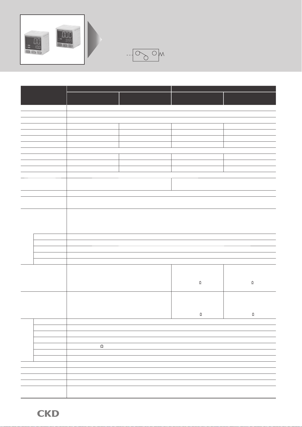
Pneumatic components (electronic pressure switch and sensors)
Design & Selection
Always read this section before starting use.
Refer to "Pneumatic, vacuum and auxiliary components CB-024SA".
Safety precautions
WARNING
Use this product in accordance of specifications.
Applications, load current, voltage, temperature, shock and
working environment, etc. exceeding the specifications
range could lead to destruction and malfunction of periph-
eral equipment.
Do not use oxygen, corrosive or combustible
gas, or toxic fluid for this product.
The pressure switch is not explosion proof. Do not use this
product in flammable atmosphere, or explosions could oc-
cur.
Do not use this product in flammable atmo-
sphere
The internal pressure in the closed chamber could change
if the fluid leaks in an accident. Use this product in the con-
trol box with safety device to control internal pressure, or
indoors with no pressure differential from the outside.
Do not install the product in completely sealed
enclosure.
Power voltage
Use the product within the specified power voltage range. If
voltage exceeding specified rage is applied, or alternating cur-
rent power (100 V AC) is applied, circuit damage could occur.
Load short circuit
Do not short-circuit the load, or circuit damage could occur.
Incorrect wiring
Avoid incorrect wiring such as connecting to the wrong electrode
of the power source, etc., or the circuit damage could occur.
CAUTION
Working fluid
When using working fluid other than air; nitrogen gas, etc.,
oxygen deficiency could be caused. Observe the following in-
structions.
Use this product in well ventilated location.
Ventilate the work area when nitrogen gas is being used.
Inspect piping regularly, so nitrogen gas does not leak.
If this product is used for vacuum suction confir-
mation, care must be taken for following matters.
The pressure exceeding withstanding pressure in the speci-
fications must not be applied to the product if positive pres-
sure of vacuum break is applied.
Working environment
Avoid use in the place that vibration or shock not less than
100m/s2is applied.
Considering errors, etc. caused by precision/
temperature characteristics, decide the setting.
When a pressure switch is used to issue interlock signals, if
high reliability is required, provide mechanical guards for a
failure, or provide dual interlock as a switch (sensor) other
than pressure switch is used. Execute inspection regularly
to check that the normal operation is done.
Care must be taken when this product is used in
an interlock circuit.
Responsiveness is adversely affected depended
on working pressure and volume of loads. Install
a regulator before the sensor if stable repeatabil-
ity is required.
Use conditions to comply with CE marking
PPX series is CE marked products complied with EMC di-
rective. EN61000-6-2; regulation matched to immunity ap-
plies to this product. Conditions below are necessary to
comply with these standards.
Conditions
Length of power line connected to the sensor is to be less than 10m.
Provide a line filter in AC power line.
Do not share power with an inverter or components causing
motor noise, etc.
Remove noise from inductive load (such as solenoid valve
and relay) with a surge suppressor such as CR or diode in
the source side.
When using components (such as switching regulator and
inverter motor) causing noise around the sensor installation
section, ground a frame ground (F.G.) terminal of compo-
nents.
Keep distance between a line connected to sensors and
strong magnetic field.
Connect a line connected to sensors with shield wire.
Connect shield wire to the ground of power side.
Take the following countermeasures to prevent
malfunction caused by noise.
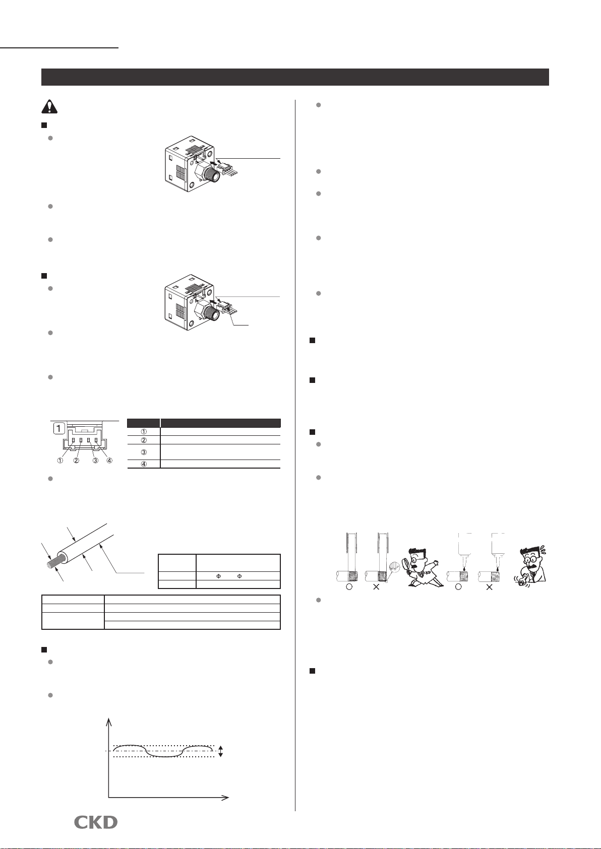
When the secondary side control pressure is re-
leased to atmosphere as air blow, pressure may
fluctuate depended on piping and blow condi-
tions. Execute a test under actual working condi-
tions or contact to CKD.
Select the product whose flow is not less than
the total of that used for sensors when selecting
a dryer, an air filter, an oil mist filter and a regula-
tor.
Intro 3

PPXSeries
Installation & Adjustment
WARNING
Avoid incorrect connection.
An incorrect connection may cause a fatal error not only to
this product but also peripheral devices.
DC power not insulated from AC primary side
may damage the product and power, so an elec-
tric shock could occur.
Do not use the product in this case.
If a switching regulator at store is used for power,
ground a frame ground (F.G.) terminal of power.
CAUTION
Do not use the product where the product is exposed to
direct-sunlight, or may come in contact with water or oil.
Avoid use in high steam and dirt environments.
Care must be taken to avoid product contact with or-
ganic solvents such as thinner, water, oil and fat.
Donotputwire,etc.intothepressure port, or diaphragm
may be damaged to prevent a normal operation.
Performance could not be guaranteed in strong
electromagnetic field.
Flash air pipe connected to sensors before con-
necting. Prevent pipe from catching tips of seal-
ing tape when piping.
Apply adequate torque when connecting pipes.
Tighten by hand at first, then use a tool to prevent screw
thread damaged.
Set screw
Tightening torque N·m
M3 0.3 to 0.6
M5 1 to 1.5
Rc1/8 3 to 5
Apply a 12mm spanner (14 mm for PPX-6G type)
on the pressure port hexagon head section to fix,
then apply tightening torque 9.8N·m or less if a
joint at store is connected to the pressure port. A
joint or the pressure port
section could be broken
if too much torque is ap-
plied.
Use seal tape to connect
joints to prevent air leak.
12mm spanner
WARNING
Sensor bracket PPX-KL is available.
If a sensor is installed with a bracket, etc., tight-
ening torque must be 0.5N·m or less.
M3 (length 6mm)
Cap screw
(Included in PPX-KL)
Sensor bracket
PPX-KL
(optional)
Panel bracket
PPX-KHS (optional)
Front cover
PPX-KCB (optional)
Panel bracket PPX-KHS (optional) and front cov-
er PPX-KCB (optional) are available.
Intro 4
Piping
Installation
Precautions

PPXSeries
Insertcablewithconnector
PPX-C* into the connector
section of this product as
right when connection.
Pull out the connector
while pressing the jaw of
cable with connector when
disconnecting.
If the cable section is pulled out without pressing the jaw
when disconnecting, the cable or connector could be bro-
ken.
Installation & Adjustment
CAUTION
Care must be taken for protection of body and lead wire.
Do not apply stress to
cable outlet or connector
section directly.
Cable with connector
(PPX-C*)
Do not dent or drop the body. Do not apply excessive re-
peated bending force and tension to lead wire, or could re-
sult in disconnection.
Connect an elastic material as a cable bearer to the mov-
able part.
Connector wiring
<Connector pin layout drawing>
Connector pin No.
Terminal name
+V
Comparison output 1
Standard type: Comparison output 2
High-function type: Analog voltage output or external input
0V
Use an applicable cable and crimp tools for housing and
contact if connected with the connector set (PPX-CN).
<Applicable cable>
Lead wire diameter
Lead wire
Conductor cross-section areas
Conductor cross-
section areas
0.12 to 0.32mm2(AWG26 to 22)
Lead wire diameter
1.0 to 1.5mm
Wire Annealed copper twist wire
Housing JST MFG CO. LTD. PAP-04V-S
Contact JST MFG CO. LTD. SPHD-001T-P0.5
Recommended
crimp tools JST MFG CO. LTD. YC-610R (AWG26 to 24)
JST MFG CO. LTD. YC-611R (AWG22)
Wiring
Connect cable with power turned OFF. Discharge static
electricity charged in human body, tool or equipment before
and during operation.
Use safety power supply with ripple voltage 10% or less
without noise. <For 24V>
Voltage
24V
Ripple ratio 10%
=10% of 24V=2.4V
2.4V
Time
Voltage must rise or fall quickly when power is turned ON
or OFF. If the rated voltage is not reached, the sensor could
malfunction. In some cases, the sensor could not recover
after the rated voltage is reached. Reset the power in that
case. Even if the voltage drops temporarily, shout down the
power once, then turn ON the power again.
Avoid use during the transient state (0.5s) when power
turned ON.
Install the product and wiring as far as possible from noise
source such as a strong electric line, etc. Take other coun-
termeasures for the surge from inductive loads on the power
line.
Do not operate the control unit, machinery or equipment
suddenly after wiring. Due to wrong setting, signals not ex-
pected could be outputted. First stop control unit, machinery
and equipment, while energize these to test. Set the target
setting after test.
Cable with 0.3mm2and over can be extended up to 100m.
Note that the power line connected to this product must be
less than 10m if used as a CE marked product.
Stop machinery and equipment, and check safe-
ty before setting switch output.
Operate the key with a fingertip. Knife, screwdriver
and other hard tip tods or objects may damage the
plastic film over the control.
Piping
Apply seal tape or sealant to screw-in joint, then screw the
joint into the port to avoid excessive torque.Apply a spanner
on the metal section to tighten.
When winding seal tape, wind the tape leaving 2mm and
over open from the thread top. If seal tape extrudes from the
thread top, seal tape chips could be created when screwed
in. These chips could enter into the circuit, and cause mal-
function.
Use pipe 1m long, and do not apply tension and impact to
the pipe. If longer pipe is used, tension not expected could
be created by the pipe weight, vibration or impact. In this
case, use an intermediate support to fix the pipe on the ma-
chine or equipment.
Do not connect relays, switches or other devic-
es to the output of this sensor in parallel at the
PLC. Do not short-circuit the PLC input terminal
connected to this sensor and (-) side of power to
test input devices, neither, or the output circuit
of this unit could be damaged.
Intro 5
Cable with connector
(PPX-C*)
Jaw
<Connector>
Contact: SPHD-001T-P0.5
Housing: PAP-04V-S
[JST MFG CO. LTD.]
Solid/
liquid
sealant
Solid/
liquid
sealant

PPXSeries
During Use & Maintenance
When unit is changed
If the product for domestic market is used with unit change
function, and if unit other than MPa and kPa is used, put the
unit label enclosed with the product on the unit display sec-
tion in the control.
PPX bar
Putting
seal label
<Unit seal label>
kPa
MPa
kgf/cm3
bar
psi
mmHg
inHg
Pressure unit label
WARNING
Do not apply overcurrent.
Duetoshort-circuitof load, ifovercurrentappliesto the pres-
sure switch, the switch could be damaged or ignite. Install
a fuse on output or power line as a overcurrent protective
circuit.
CAUTION
Do not disassemble the product.
Disassembling the product could result in damage or deterio-
ration of the product. CKD will not guarantee the performance
after disassembling. When replacing or moving the product,
remove the sensor without disassembling pressurized port.
Stop machinery and equipment, then check the
safety before operating the product.
The case is made of resin. Do not use solvent, alcohol or any
other cleaning agent, etc., to remove contamination, etc., or resin
could be corroded or damaged. Wipe contaminations with a well
wrung rag, etc., after soaked in weakened neutral detergent.
Care must be taken for disconnection and reverse current
caused by wiring resistance. When components including
pressure switches are connected to the same power source
of pressure switch, if (-) sides of output and power lines are
short-circuited to check input devices of the control panel, or if
(-) side of power line is disconnected, reverse current may ap-
ply to the output circuit of pressure switch, causing damages.
Take countermeasures as followings to prevent
damages caused by reverse current.
Do not concentrate current to the power line, especially, (-)
side power line, and use wire as fat as possible.
Limit numbers of components connected to the same pow-
er source of pressure switch.
Connect a diode in series to the pressure switch output line to prevent reverse current.
Connect a diode in series to power line (-) side of the pres-
sure switch to prevent reverse current.
Other components
Control panel
Main circuit
PLC input
Diodetoprevent
reverse flow
Pressure switch
Current
from other
components
Disconnection
Test SW or
short-circuit
Care must be taken for surge current leading.
When the power is shared with inductive loads that
create surge current such as pressure switches,
solenoid valves or relays, if the circuit is closed
with inductive loads activated, surge current could
lead to the output circuit, causing damages.
Take countermeasures as followings to prevent
damage caused by surge current leading.
When components are connected with connec-
tors, if a connector is dislocated during ener-
gizing, the output device could be damaged be-
cause of the reason above. Turn off the power
before dislocating a connector.
Separate outputs creating inductive load such as solenoid
valve and relay, etc. and power of inputs such as pressure
switch, etc.
If the power can not be separated from the inductive load,
install a surge suppressor per load. The surge suppressor
connected to PLC, etc. merely protects the unit connected.
Connect surge suppressors to the points as following to re-
duce damages when lines are disconnected.
Input
components
Input
components
Input
components
Pressure switch
Main circuit
Relay
Surge current
Solenoid valve
Surge absorbing ele-
ment (later installation)
Disconnection or circuit shut-
down caused by emergency stop
Surge absorbing
element (integrated)
Output of PLC
PC
ON
Intro 6
Precautions

1
JIS symbol
Digital pressure sensor
PPXSeries
Specifications
Descriptions Standard type High-function type
Low pressure
PPX-R01* High pressure
PPX-R10* Low pressure
PPX-R01*H High pressure
PPX-R10*H
Pressure sensitive element
Diffused semiconductor pressure sensor
Working fluid Air/non-corrosive gas
Type of pressure Gauge pressure
Rated pressure range
Note
1 -100.0 to +100.0kPa -0.100 to +1.000MPa -100.0 to +100.0kPa -0.100 to +1.000MPa
Set pressure range -100.0 to +100.0kPa -0.100 to +1.000MPa -100.0 to +100.0kPa -0.100 to +1.000MPa
Display unit kPa MPa kPa MPa
Minimum display unit 0.1KPa 0.001MPa 0.1KPa 0.001MPa
Unit change Only available for domestic market (-KA) (MPa, kPa, kgf/cm2, bar, psi, mmHg, inchHg)
Withstanding pressure 500kPa 1.5MPa 500kPa 1.5MPa
Repeatability ±0.1%F.S. (within ±2 digits) ±0.2%F.S. (within ±2 digits) ±0.1%F.S. (within ±2 digits) ±0.2%F.S. (within ±2 digits)
Temperature characteristics (+20 °C reference)
Within ±0.5%F.S. Within ±1%F.S. Within ±0.5%F.S. Within ±1%F.S.
Indicator 4 + 4 digit 3 color LCD display (display update cycle: 250ms and 1000ms, select with key operation.)
Indicator light Orange LED
(Comparison output 1 operational indicator light, comparison output 2 operational
indicator light: comparison output ON lighting)
Orange LED
(Comparison output 1 operational indicator light: comparison output ON lighting,
analog voltage output operation display light: lighting during setting)
Power voltage 12 to 24V DC±10% ripple P-P10% or less
Power consumption Normal: 840mW or less (current consumption 35mA or less at 24 V power)
ECO MODE: 600mW or less at STD (current consumption 25mA or less at 24 V power) and 480mW or less at FULL (current consumption 20mA or less at 24 V power)
Comparison
output
(switch output)
Note 1
<NPN output type>
NPN transistor and open collector
• Max. inrush current: 100mA
•
Impress voltage: 30V DC or less (between comparison output and 0V)
•
Residual voltage: 2V or less (at inrush current 100mA)
<PNP output type>
PNP transistor and open collector
• Max. output current: 100mA
•
Impress voltage: 30V DC or less (between comparison output and +V)
•
Residual voltage: 2V or less (at output current 100mA)
Output operation Select NO/NC with the key operation.
Output mode EASY MODE/HYSTERESIS MODE/WINDOW COMPARATOR MODE
Hysteresis (hysteresis)
Min. 1 digit (variable)
Response time 2.5ms, 5ms, 10ms, 25ms, 50ms, 100ms, 250ms, 500ms, 1000ms and 5000ms, select with key operation.
Short circuit protection
Equipment
External input
(Auto-reference/remote
zero adjusting)
-
<NPN output type>
ON voltage: 0.4V DC or less
OFF voltage: 5 to 30V DC or release
Input impedance: 10k
Input time: 1ms and over
<PNP output type>
ON voltage: 5V to +V DC
OFF voltage: 0.6V DC or less or release
Input impedance: 10k
Input time: 1ms and over
Analog output
-
Output voltage: 1 to 5V
Zero point: Within 3V±5%F.S.
Span: Within 4V±5%F.S.
Linearity: Within ±1%F.S.
Output impedance: 1k
Output voltage: 0.6 to 5V
Zero point: Within 1V±5%F.S.
Span: Within 4.4V±5%F.S.
Linearity: Within ±1%F.S.
Output impedance: 1k
Environment conditions
Protective structure
IP40 (IEC)
Ambient temperature
-10 to +50°C or to store: -10 to +60°C
Ambient humidity
35 to 85%RH (to be no dew condensation and unfrozen.) or to store: 35 to 85%RH
Withstanding voltage
1000V AC for one minute applied to all charged sections and between cases
Insulation resistance
50M and over with 500 V DC mega applied to all charged sections and between cases
Mechanical vibration proof
Endurance 10 to 500Hz, compound amplitude 3mm, 2 hours to each XYZ direction (to mount on panel: endurance 10 to 150Hz, compound amplitude 0.75mm, 2 hours to each XYZ direction)
Mechanical shock proof
Endurance 100m/S2(10 G), 3 times to each XYZ direction
Connection Connector
Port size
Note 1
M5 female thread +R (PT) 1/8 male thread
Wire length
Available up to 100m (less than 10m when CE marking complied) with cable not less than 0.3mm2when wiring is extended.
Weight Product weight: 40g, weight including package: 135g
Accessory
Note 2
PPX-C2 (2m cable with connector): 1 pcs.
Unit seal label (for -KA with unit change): MPa, kPa, kgf/cm2, bar, psi, mmHg, inchHg
Note 1: Refer to <table 1> on the following page for the products for the foreign markets.
Note 2: Cable with connector is not included for (-J).

2
PPXSeries
E
Unit change
D
Connector cable
<How to order for foreign markets>
PPX- R01 N- 6M - - KA
A
Pressure range
BOutput type
Symbol Descriptions
APressure range
R01 -100.0 to 100.0kPa
R10 -0.100 to 1.000MPa
BOutput type
NNPN transistor output 2 point (standard type)
PPNP transistor output 2 point (standard type)
NH
NPN transistor output 1 point + analog voltage output or external input (high-function type)
PH
PNP transistor output 1 point + analog voltage output or external input (high-function type)
CPiping shape
6M Note 1 R1/8, M5
6N NPT1/8, M5
6G Note 2 G1/8, M5
DConnector cable
Blank With connector cable
J Note 3 Without connector cable
EUnit change
KA With unit change function
Symbol Descriptions
APressure range
R01 -100.0 to 100.0kPa
R10 -0.100 to 1.000MPa
BOutput type
NNPN transistor output 2 point (standard type)
PPNP transistor output 2 point (standard type)
NH
NPN transistor output 1 point + analog voltage output or external input (high-function type)
PH
PNP transistor output 1 point + analog voltage output or external input (high-function type)
CPiping shape
6M R1/8, M5
DConnector cable
Blank With connector cable
J Note 1 Without connector cable
Destination
Switch output
Unit
Unit
change
Unit seal label to be
attached Note 1
Piping port
NPN PNP
Domestic kPa/MPa
--
R1/8(M5)
Asia
-
kPa/MPa R1/8(M5)
Europe
-
kPa/MPa G1/8(M5)
North America
kPa/MPa NPT1/8(M5)
Symbol Descriptions
C1 Cable with connector 1m
C2 Cable with connector 2m
C3 Cable with connector 3m
C5 Cable with connector 5m
CN
Connector set (10 pcs. per set)
KL Bracket (set screw attached)
KHS Panel bracket
KCB
Front protective cover (when panel bracket used)
Type Model no. Port size Output type Remarks
Standard type PPX-R01N-6M-(J)-KA M5 female thread +R (PT) 1/8
male thread NPN transistor and open collector For Asia
PPX-R10N-6M-(J)-KA
High-function type
PPX-R01NH-6M-KA
PPX-R10NH-6M-KA
Standard type PPX-R01P-6G-(J)-KA M5 female thread +G1/8 male
thread PNP transistor and open collector For Europe
PPX-R10P-6G-(J)-KA
High-function type
PPX-R01PH-6G-KA
PPX-R10PH-6G-KA
Standard type
PPX-R01N-6N-(J)-KA
M5 female thread +NPT1/8 male
thread
NPN transistor and open collector
For North
America
PPX-R01P-6N-(J)-KA PNP transistor and open collector
PPX-R10N-6N-(J)-KA NPN transistor and open collector
PPX-R10P-6N-(J)-KA PNP transistor and open collector
High-function type
PPX-R01NH-6N-KA NPN transistor and open collector
PPX-R01PH-6N-KA PNP transistor and open collector
PPX-R10NH-6N-KA NPN transistor and open collector
PPX-R10PH-6N-KA PNP transistor and open collector
How to order
<How to order for domestic market>
PPX- R01 N- 6M -
A
Pressure range
BOutput type
CPiping shape
D
Connector cable
Note 1: It is available only if Boutput type "N" or "P" is selected.
With the new Measurement Law, the product with the unit change function for foreign markets can not be used in Japan.
Note 1: Boutput type "N" or "NH" is only available.
Note 2: Boutput type "P" or "PH" is only available.
Note 3: It is available only if Boutput type "N" or "P" is selected.
Note 1: Refer to Intro 6 for the unit seal label to be attached.
C
Piping shape
PPX- C1
Discrete option model no.
<Table 1>
How to order

3
PPXSeries
Analog output voltage - pressure characteristics
PPX-R01NH
•
R01PH
PPX-R10NH
•
R10PH
5
1
Voltage
(V) 3
-100.0 0 100.0(kPa)
Pressure
5
1
0.6
-0.100 0 1.000(MPa)
Pressure
Voltage
(V)

4
PPXSeries
Dimensions
PPX-R**-6M/6N (R/NPT thread)
•
PPX-R**-6G (G thread)
•
Dimensions
30
30
Output 1 operational
indicator light
Output 2 operational
indicator light or analog
output indicator light
Mode change switch
Setting UP key
Setting DOWN key
Pressure unit
Sub-display section
(4 digit LCD display)
Main display section
(4 digit LCD display)
25.5 7.5 9.5
1.5 R1/8
NPT1/8
20
20
M3 female thread depth 4
M5 female thread
12
Connector
42.5
30
30
Output 1 operational
indicator light
Output 2 operational
indicator light or analog
output indicator light
Mode change switch
Setting UP key
Setting DOWN key
Pressure unit
Sub-display section
(4 digit LCD display)
Main display section
(4 digit LCD display)
25.5 10 7
1.5 G1/8
42.5
20
20
M3 female thread depth 4
M5 female thread
14
Connector

5
PPXSeries
Dimensions with options
Bracket (PPX-KL)
•
Panel bracket (PPX-KHS) installation drawing
•
Panel cut dimensions
Installing 1 pc. Installing consecutive n pcs. horizontally. Installing consecutive n pcs. vertically.
(Note 1): Panel thickness must be 0.5 to 6mm. (Note 1): Panel thickness must be 0.5 to 6mm.
31 0
-0.4
31 0
-0.4
31 X n pcs. +3.5 X (n pcs. -1)
55 and over
31 0
-0.4
55 and over
31 X n pcs. +3.5 X (n pcs. -1)
31 0
-0.4
7.2
34.5
18.3
8.7 Panel thickness 1 to 6
34.5
33.4
50
24
33.4
Connector
14.5
30
9.5
4.2
22
20
2.3
1
2- 3.5
2-R2.1
13
20
R13
(5.3)
20
2
5.5
44
30
30
15
45
35
1.5
42.5
9.5 NPT1/8
R1/8
5
30
2
12
M5
22
2-R2.1
4.2
9.5
25.5 14.5
Installation drawing

6
PPXSeries
Model no.
Cable length
PPX-C1 1m
PPX-C2 2m
PPX-C3 3m
PPX-C5 5m
Dimensions with options
Front protective cover (PPX-KCB) installation drawing
•
Cable with connector (PPX-C*)
•
(35)
(8)
A
L
(50)
(8)
3.7 cable
Connector set (PPX-CN)
•Housing: JST MFG CO. LTD. PAP-04V-S
Contact: JST MFG CO. LTD. SPHD-001T-P0.5
•
•
Dimensions with options
Blue
White
Black
Brown
Isolator color Terminal
number View A
Housing
PAP-04V-S
Contact (crimping)
SPHD-001T-P0.5
(JST MFG CO. LTD.)
Front protective cover (when panel bracket used)
34.5
34.5
39.3
20
11 18.3
Panel thickness 0.5 to 6
33.4
33.4
24
50
Connector

7
PPXSeries
Circuit and connection methods
Standard type
•NPN output type
Leakage inspection (high-function type)
•
Lead wire color of cable with connector
Load Load
(White) comparison output 2
(Brown) +V
(Black) comparison output 1
(Blue) 0V
100mA MAX.
100mA MAX.
Example of external connectionInternal circuit
Main circuit
12 to 24V DC
±10%
+
-
5V
(Black)
(Brown) +V
(White) external input
(Blue) 0V
12 to 24V DC
±10%
+
-
1k
Main circuit
<Example of external input connection>
5V
1k
Example of external connectionInternal circuit
Lead wire color of cable with connector
Load
(Black) comparison output 1
(Brown) +V
(White) analog voltage
output or external input
(Blue) 0V 100mA MAX.
12 to 24V DC
±10%
+
Main circuit
-
Standard type
•PNP output type
Main circuit
Example of external connectionInternal circuit
Lead wire color of cable with connector
100mA MAX.
100mA MAX.
Load Load
12 to 24V DC
±10%
+
-
(White) comparison output 2
(Brown) +V
(Black) comparison output 1
(Blue) 0V
Leakage inspection (high-function type)
•<Example of external input connection>
Main circuit
1k
(Black)
(Brown) +V
(White)
external input
(Blue) 0V
12 to 24V DC
±10%
+
-
Main circuit
1k
Example of external connectionInternal circuit
Load
100mA MAX.
Lead wire color of cable with connector
(Black) comparison output 1
(Brown) +V
(Blue) 0V
12 to 24V DC
±10%
+
-
(White) analog voltage
output or external input

8

PPXSeries
9
Output 1 operational indicator light
Comparison output 1 ON lighting
Output 2/analog voltage output
operational indicator light
Mode switchover key
Standard type: Comparison
output 2 ON lighting
High-function type: Analog
voltage output lighting
during setting
Main display section
Sub-display
section
Setting
UP key Setting
DOWN key
Pressure port
Connector
Output mode and output operation
The output mode for comparison output 1 and comparison output 2 can be selected from EASY MODE, HYSTERESIS MODE and
WINDOW COMPARATOR MODE.
Refer to "Comparison output 1/2 output mode setting" in the menu setting mode section on page 12 for the details.
•
This mode controls ON/OFF of comparison output.
•EASY MODE
Name of display and controls
(Note 1): Hysteresis varies with 8 steps.
Refer to "Switching fixed hysteresis value" in "PRO MODE" on page 13 for the setting method.
(Note 2): " " is displayed in the sub-display section for comparison output 1, while " " for comparison output 2.
This mode controls ON/OFF of comparison output with setting hysteresis randomly.
•Hysteresis mode
(Note 1): " " and " " are displayed in the sub-display section for comparison output 1, while " " and " " for comparison output 2.
This mode controls ON or OFF of comparison output within set pressure range.
•WINDOW COMPARATOR MODE
(Note 1): Hysteresis varies with 8 steps.
Refer to "Switching fixed hysteresis value" in "PRO MODE" section on page 13 for the setting method.
(Note 2): " " and " " are displayed in the sub-display section for comparison output 1, while " " and " " for comparison output 2.
Comparison output
Pressure
P
0
ON
OFF
H (hysteresis)
H: fixed hysteresis value (Note 1)
Comparison output
Pressure
Hi
0
ON
OFF
H (hysteresis)
H: 1 digit and over
Lo
2 digits and over
when using psi unit
Comparison output
Pressure
Hi
0
ON
OFF
Lo
H (hysteresis)
H (hysteresis)
H: fixed hysteresis value (Note 1)

PPXSeries
10
(Note 1): The mode is switched to menu setting mode in 2 seconds after pressing the mode switchover key, however, keep it press down.
<Installation procedure>
RUN MODE
This is the pressure detection state.
Refer to "RUN MODE" (page 10,
11).
Hold down for 2 s.
Hold down for 4 s. (Note 1)
Menu setting mode
This is easy setting mode.
Refer to "menu setting mode" on
page 12.
PRO MODE
This is detailed setting mode.
Refer to "PRO MODE" on page 13.
Setting
RUN MODE
Threshold value setting
Refer to <setting comparison output 1/2 output mode> and <switching analog voltage output/external input> in the "menu setting mode" on
page 12 for the setting conditions.
•
(Note 1): If set pressure range is overflowed, " " (upper limit over) or " " (lower limit over) is displayed in the sub-display section.
When setting threshold value in "hysteresis mode/window comparator mode", if Hi side threshold value is smaller than Lo
side threshold value, " " is displayed.
The sub-display section display is only switched when setting the
threshold value, so the following diagram shows only sub-display section.
<RUN MODE state>
Auto
Auto
Auto
Auto
Auto
Auto
Auto
<For standard type>
<Setting conditions >
Comparison output 1 output mode: " " (EASY MODE)
Comparison output 2 output mode: " " (OFF)
<Setting conditions >
Comparison output 1 output mode: " " (EASY MODE)
Comparison output 2 output mode: " " (EASY MODE)
<Setting conditions >
Comparison output 1 output mode: " " (EASY MODE)
Comparison output 2 output mode: " " (hysteresis mode) or
"" (window comparator mode)
<Setting conditions >
Comparison output 2 output mode: " " (OFF)
Comparison output 1 output mode: " " (hysteresis mode) or
"" (window comparator mode)
How to operate
<RUN MODE state>
<RUN MODE state>
<RUN MODE state>

PPXSeries
11
Zero adjusting is the function that pressure display is forcibly set to
"zero" when the pressure port is released to atmospheric pressure.
•Zero adjusting
<Setting conditions >
Comparison output 1 output mode: " " (EASY MODE)
Analog voltage output/external input switching: " " (analog voltage output)
<Setting conditions >
Comparison output 2 output mode: " " (EASY MODE)
Comparison output 1 output mode: " " (hysteresis mode) or
" " (window comparator mode)
<Setting conditions >
Comparison output 1 output mode: " " (hysteresis mode) or
" " (window comparator mode)
Comparison output 2 output mode: " " (hysteresis mode) or
" " (window comparator mode)
<For high-function type>
<Setting conditions >
Comparison output 1 output mode: " " (EASY MODE)
Analog voltage output/external input switching: " " (auto-reference input) or
" " (remote zero adjusting input)
<Setting conditions >
Comparison output 1 output mode: " " (hysteresis mode) or
"" (window comparator mode)
Analog voltage output/external input switching: " " (analog voltage output)
<Setting conditions >
Comparison output 1 output mode: " " (hysteresis mode) or
" " (window comparator mode)
Analog voltage output/external input switching: " " (auto-reference input) or
" " (remote zero adjusting input)
(Note 1): Auto-reference and remote zero adjusting values are displayed.
Refer to "Auto-reference" section on page 15 and "Remote zero
adjusting" section on page 16 for the details.
<Common>
Key lock is the function that rejects key operation as the each
setting mode is not changed incorrectly.
•Key lock
Peak/bottom hold
Peak/bottom hold is the function that displays peak and bottom
values of fluctuated pressure.
Peak value is displayed in the main display section, and bottom
value is displayed in the sub-display section.
•
•
Auto
Auto
Auto
Auto
Auto
Auto
Auto
Auto
Auto
Auto
Auto
Alternately blinking
(Note 1)
Press for several seconds
Auto
<Key lock setting>
<Key lock release>
Press for several seconds
Auto
(Key lock setting)
Press for several seconds
Auto
(Key lock release)
<Peak and bottom hold setting>
<Peak and bottom hold release>
Press for several seconds
Alternately blinking
Press for several seconds Alternately blinking
Auto
Alternately blinking
(Note 1)
<RUN MODE state>
<RUN MODE state>
<RUN MODE state>
<RUN MODE state>
<RUN MODE state>
<RUN MODE state>
Other manuals for PPX Series
2
Table of contents
Other CKD Accessories manuals

CKD
CKD Rapiflow FSM2-N Series User manual

CKD
CKD Rapiflow FSM2 Series User manual

CKD
CKD WKF2 Series User manual

CKD
CKD FLUEREX WFK2 Series User manual

CKD
CKD PPX Series User manual

CKD
CKD RAPIFLOW FSM2-D Series User manual

CKD
CKD RAPIFLOW FSM3 Series User manual

CKD
CKD PFD Series User manual

CKD
CKD WFC Series User manual

CKD
CKD FLUEREX PF Series User manual