................~.~.~~......................:.:.,
~ :$$::::$&y::<: :yyg$:yy.
PRODUCT
*.:.:.:<<.:.:.:.p
*.*...v.-2.2.
..;.:.:.#y
.*.%..-.v..
v
‘:$@
f:.’
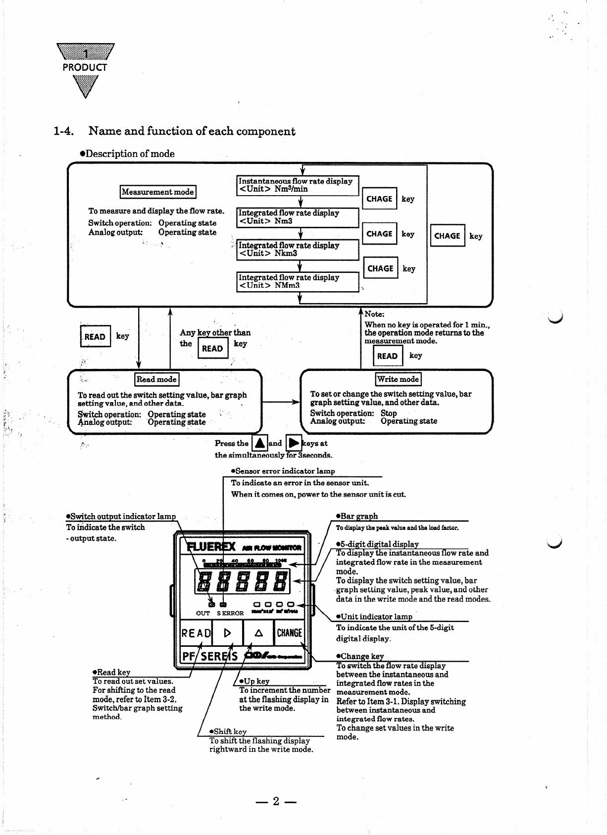
l-4, Name and function of each component
*Description of mode
Measurement mode
To measure and display the flow rate. Integrated flow rate display
Switch operation: Operating state <Unit> Nm3
Analog output: Operating state +
CHAGE
key
‘ . ? .r Inngr-.d&rate display ‘lzl
I Jr I
. I 4
+Note:
1CHAGE 1
key
’ !
cl
.R~AD kei
Anyke otherthan
the READ lrey
T-l
When no key is operated for 1min.,
the operation mode returns to the
m;asuremyt mode.
L-J
READ key
pE%ZiZ]
To read out the switch setting value, bar graph
setting value, and other data. \
Switch operation: Operating state ;.
&.lalog output: ‘Operating state
To set or change the switch setting value, bar
graph setting value, and other data.
Switch operation: Stop
halog output: Operating state
the simulGuslyforseconds.
*Sensor error indicator lamp
When it comeson, power to the sensor unit is cut.
-output state. and
nt
switch setting value, bar
value, peak value, and other
ite mode and the read modes.
digital display.
To shift the flashing display
rightward in the write mode.
measurement mode.
Refer to Item 3-1. Display switching
between instantaneous and
integrated flow rates.
To change set values in the write