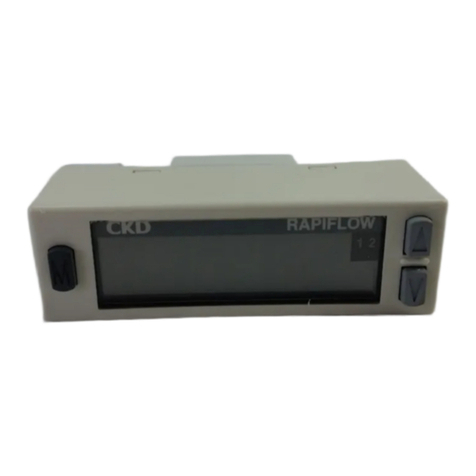
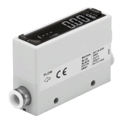
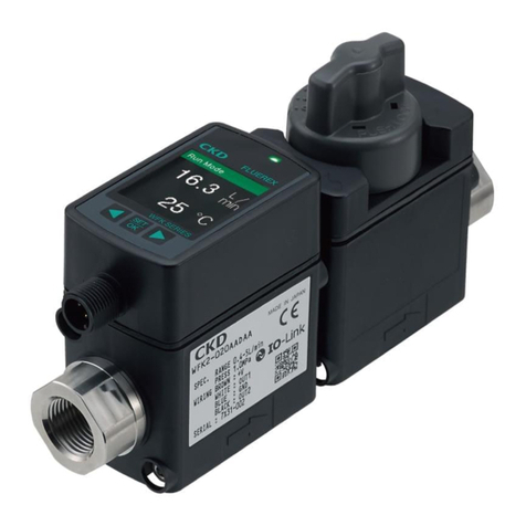
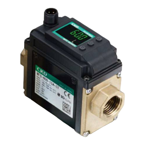
CKD Rapiflow FSM2 Series User manual

SM-385853-A
INSTRUCTION MANUAL
SMALL SIZE
FLOW SENSOR
RAPIFLOW
FSM2 Series
●
Please read this instruction manual carefully
before using this product, particularly the
section describing safety.
●
Retain this instruction manual with the
product for further consultation whenever
necessary.
2
nd
EDITION
・
Integrated indicator type (FSM2-N/P series)
・
Separated indicator type (FSM2-A series)
・
Integrated indicator type
(
Integrated needle valve type
)
Discontinue

[SM-385853-A]
1
Safety precautions
Always read before starting use.
When designing and manufacturing a device using CKD products, the manufacturer is obligated to check
that device safety mechanical mechanism, pneumatic control circuit, or water control circuit and the
system operated by electrical control that controls the devices is secured.
It is important to select, use, handle, and maintain the product appropriately to ensure that the
CKD product is used safely.
Observe warnings and precautions to ensure device safety.
Check that device safety is ensured, and manufacture a safe device.
①
This product is designed and manufactured as a general industrial machine part.
It must be handled by an operator having sufficient knowledge and experience in
handling.
②
Use this product in accordance of specifications.
Contact CKD when using the product outside the unique specifications range, when using it outdoors,
and when using it under the conditions and environment below.
Do not attempt to modify or additionally machine the product.
(1) Use for special applications requiring safety including nuclear energy, railroad, aviation, ship, vehicle, medical
equipment, or applications coming into contact with beverage or food, amusement equipment,
emergency shutoff circuits, press machine, brake circuits, or for safeguard.
(2) Use for applications where life or assets could be adversely affected, and special safety measures are required.
③
Observe corporate standards and regulations, etc., related to the safety of device
design and control, etc.
ISO 4414, JIS B 8370 (pneumatic system rules)
JPAS 005 (policy for pneumatic cylinder use and selection)
High Pressure Gas Maintenance Laws Occupational Safety and Sanitation Laws,
and other safety rules, association standards and regulations.
④
Do not handle, pipe, or remove devices before confirming safety.
(1) Inspect and service the machine and devices after confirming safety of the entire system related to this
product.
(2) Note that there may be hot or charged sections even after operation is stopped.
(3) When inspecting or servicing the device, turn off the energy source (air supply or water supply),
and turn off power to the facility. Discharge any compressed air from the system, and pay enough attention
to possible water leakage and leakage of electricity.
(4) When starting or restarting a machine or device that incorporates pneumatic components, make sure
that the system safety, such as pop-out prevention measures, is secured.
⑤
Observe warnings and cautions on the pages below to prevent accidents.
■
The Safety cautions are ranked as "DANGER", "WARNING" and "CAUTION" in this section.
Note that some items described as "CAUTION" may lead to serious results depending on the situation.
In any case, important information that must be observed is explained.
!
Warning
!
When a dangerous situation may occur if handling is mistaken leading to fatal
or serious injuries, or when there is a high degree of emergency to a warning.
When a dangerous situation may occur if handling is mistaken leading to fatal
or serious injuries.
When a dangerous situation may occur if handling is mistaken leading to minor
injuries or physical damage.
WARNING:
!
DANGER:
CAUTION:
!
!

Discontinue

[SM-385853-A]
−
2
−
DESIGN AND SELECTION
Working fluid
●
Do not use this product for flammable fluids.
Working environment
●
Explosion-proof environment
Never use this product in an explosive gas atmosphere. The
structure is not explosion-proof, and explosions or fires could occur.
Working fluid
●
This product cannot be used as a business meter.
This product does not comply with Measurement Laws, and cannot
be used for commercial business. Use this as an industrial sensor.
●
Do not use fluids other than the applicable fluid because accuracy
cannot be guaranteed.
●
Compressed air from the compressor contains drainage (water, oil
oxide, foreign matters, etc.). So install a filter, air dryer, and oil mist
filter (micro alescer) on the primary side (upper stream side) of the
sensor. The sensor's meshing rectifies flow in the pipe. It does not
filter out foreign matters, so provide a filter.
<Recommended Circuit>
●
When using a valve on the primary side of the sensor, use only a
valve with oil-prohibited specifications. This sensor could malfunction
or fail if exposed to splattering grease, oil, etc. Friction powder could
be generated depending on the valve, so mount a filter to prevent the
powder from entering the sensor.
●
When using the valve with liquified gases such as carbon dioxide,
always vaporize the gas. Faults could result if the liquified gas enters
this product.
●
Use dry gas which does not contain corrosive elements such as
chlorine, sulfur or acids, and which is clean and does not contain
dust or oil mist.
●
Depending on the fluid, retaining the fluid for a long time could
adversely affect the performance. Do not seal the fluid in the pipe for
long periods of time.
Working environment
●
Corrosive environment
Do not use this product in an atmosphere containing corrosive gases
such as sulfur dioxide.
●
Ambient temperature/fluid temperature
Use ambient temperature/fluid temperature from 0 to 50°C within
specified range. Even if the temperature is within the specified range,
do not use this product if the ambient temperature and fluid
temperature could suddenly change and cause dew to condense.
●
Max. working pressure specified flow rate range
Applications exceeding the max. working pressure and specified flow
rate range may result in faults. Use this product only within the
specified range.
●
Drip-proof environment
The degree of protection of this product is equivalent to IP40. Do not
!
DANGER:
!
WARNING:
filter
Oil mist filter
(
micrialescer
)
Regulator
Air dryer FSM2 series
Pneumatics
Pressure source
Discontinue

[SM-385853-A]
−
3
−
install this product where water, salt, dust, or swarf is present or in a
pressurized or depressurized environment. This product cannot be
used where the temperature changes greatly or where high humidity
environment could cause damage through dew condensation.
Flow rate unit
●
This product's flow rate is measured at a mass flow rate unaffected
by temperature or pressure. The unit is /min., but this is the display
when the mass flow rate is converted to volumetric flow rate at 20°C
1 barometric pressure (101 kPa)
,
and relative humidity 65%.
Proof pressure
●
Please note the difference when you select the series.
Overflow
●
With each series, no problem will occur in the sensor, even if an
overflow double the measurement range. If dynamic pressure is
applied near the max. working pressure (when a pressure difference
exceeding the max. working pressure is applied between primary
and secondary sides), a problem could occur with the sensor. If
dynamic pressure is applied, such as when a workpiece is filled for
leakage inspection, provide a bypass circuit or restrictor so that
dynamic pressure is not applied to the sensor.
Use for suction confirmation, etc.
●
When this product is used to confirm suction, etc., select the flow rate
range based on the operating vacuum pressure and suction nozzle.
Refer to Page 65 on the attached sheet for “5.Technical data [5.1How
to select flow sensor]”
●
When this product is used to confirm suction, etc., provide an air filter
upstream from suction to prevent the entry of foreign matter.
●
When this product is used to confirm vacuum, etc., consider the
atmospheric dew point and this product’s ambient temperature, and
use the product under conditions in which dew does not condense in
pipes.
●
When this product is used to confirm suction, etc., response time
may be delayed by the capacity of the pipe between the suction
nozzle and this product. In this case, take countermeasures to
reduce piping capacity.
●
When this product is used for vacuum applications such as air
suction, do not bend the tube near the push-in fitting. If stress is
applied to the tube near the push-in fitting, insert an insert ring into
the tube, and connect the tube to the push-in fitting.
Using for leakage inspections
●
The working pressure range of this product is -0.09 to 1.00 MPa. If it
is energized in a vacuum state of -0.09 MPa or less, the sensor’s
heat dissipation performance will drop and could degrade the sensor.
●
When the suction confirmation sensor is switched from a pressure
sensor (switch) to a flow rate sensor (switch), sensor output (switch
output) logic will be reversed. Refer to the drawing below.
Note that the PLC sequence program must be changed or revised.
Pressure sensor (switch) Flow sensor (switch)
Adsorption
verification
Setpoint and over ON Setpoint or less ON
ON
OFF
Atmospheric
pressureside
Highvacuum
side
ON
OFF
Flowrate
0side
Flowrate
largeside
!
CAUTION:
!
WARNING:
Discontinue

[SM-385853-A]
−
4
−
If source pressure or vacuum source is not supplied when device
power is turned on, “flow rate 0” = “sensor output (switch output) ON”
status is set at the flow rate sensor (switch). Check that this is not
a problem with the PLC sequence program, etc.
INSTALLATION & ADJUSTMENT
Piping
●
Always attach the pipes before starting wiring.
●
Align the fluid flow direction to the direction indicated on the pipe
when connecting the pipes.
●
When installing the sensor on piping, refer to the torque below so
that excessive screw-in torque or load torque is not applied to the
connection port.
[Reference value]
Set screw Tightening torque N
・
m
M5 1.0 to 1.5
Rc1/8 3 to 5
Rc1/4 6 to 8
Rc1/2 16 to 18
●
Before piping, clean out the pipes using air blower to remove all
foreign matter and cutting chips from the pipes. The rectifier or
sensor chip could be damaged if an entry of a large amount of
foreign matter, cutting chips, etc., occurs.
●
Attach a wrench to metal sections when tightening pipes so that
pressure is not applied to the resin section.
●
Check that sealant tape or sealant material does not get inside
during piping. * When using for clean room specifications, make sure
that the sealant material matches the system.
●
Connect a fitting even when using the metal body type with the OUT
side opened. The port filter could come off.
●
When using a push-in fitting, accurately insert tube and confirm that it
is not dislocated even when pulled. Cut tube at a right angle with a
dedicated cutter before use.
●
Make sure that the leakage detection solution does not enter the
case when inspecting the pipe for leaks.
●
Do not install the regulator/solenoid valve, etc immediately before to
this product. Incorrect flow could cause errors. Provide a straight
piping section if required.
!
CAUTION:
!
CAUTION:
Discontinue

[SM-385853-A]
−
5
−
●
Although the mounting is "unrestricted in vertical/horizontal
direction", the flow rate may vary depending on difference in the
mounting orientations or piping conditions.
About Mounting
●
The display integrated type's flow rate meter uses a liquid crystal
display, which may be difficult to read depending on the angle.
●
Do not install the product in a manner that the bodies contact each
other. The evolution of heat from each other could cause the
generation body's temperature rise and enhance the change in
characteristics or the deterioration of the resin materials. When using
the products in a row, set intervals of distance of 10 mm and over.
●
This product can be installed in any direction; top, bottom, left, or
right.
Note of Integrated needle valve type
●
This valve cannot be used as a stop valve that has no leakage. Slight
leakage is allowed in product specifications.
●
The flow path in the needle valve is not completely free of dust
generation. A final clean filter should be used in circuits where dust
generation could be a problem.
●
Do not turn the dial forcibly when fully closing or opening it (0.05 Nm
or less). Do not use the lock nut to adjust the needle. Otherwise this
could cause needle galling or damage.
●
The set flow rate may vary if turning the dial of the needle valve
forcibly when fully closing. Take care not to turn the dial forcibly when
setting a very small flow rate.
●
When you install the panel, please install this product after piping
etc.
●
Check that lock nuts are not loose. Actuator speed cannot be
controlled if the lock nut is loose.
●
A stopper mechanism is provided, but damage could result if
the needle is turned too far.
Bracket (separate sales)
Model no. : FSM2-LB1
Port size: Push-in joint 4
、
6
、
8
、
10
Rc1/8
、
Rc1/4
、
M5
Bracket (separate sales)
Model no. : FSM2-LB2
Port size: Rc1/2
!
CAUTION:
Vertical mount
(with bottom thread)
Horizontal mount
(with through hole)
Bracket mount (with bracket)
Installed screw Installed screw
Installed screw
Installed screw Installed screw
!
CAUTION:
Discontinue

[SM-385853-A]
−
6
−
About Wiring
●
Use power supply voltage and output within the specified voltage. If
voltage exceeding the specified voltage is applied, the sensor could
malfunction or be damaged, or electrical shock or fire could occur.
Do not use any load that exceeds the rated output. Failure to
observe this could result in output damage or fire.
About Wiring
●
Check line color when wiring. Incorrect wiring could result in sensor
damage and malfunctions, so check wire color against the instruction
manual before wiring.
●
Check wiring insulation.
Check that wires do not contact other circuits and that there are no
ground faults or insulation faults across terminals. Overcurrent could
flow in and damage the sensor.
●
Use a stabilized DC power supply within the specified rating that has
been insulated from the AC power supply. A noninsulated power
supply could result in electrical shock. If power is not stabilized, the
peak value could be exceeded. This could damage the product or
impair accuracy.
●
Always attach the connector bar
after connecting the connector.
●
Check that stress (7 N and over)
is not directly applied to cable lead
outs or connectors.
●
Stop the control device and equipment
and turn power off before wiring. Starting operation suddenly could
cause unpredictable operation and hazards. Conduct an energized
test with controls and machine devices stopped, and set target switch
data. Be sure to discharge any accumulated electrostatic charge
among personnel or tools before and during work. Connect and wire
bending resistant material, such as robot wire material for movable
sections.
●
Do not use this product at levels exceeding the power supply voltage
range. If voltage exceeding this range is applied or if AC power is
applied, the controller could rupture or burn.
●
Install this product and wiring far away from sources of noise, such as
power distribution wires. Provide separate countermeasures for
surge applied to the power cable. The display or output could
fluctuate.
●
Do not short-circuit the load. The product could break or burn.
●
The power supply for the metal body (stainless steel body, aluminum
body) type is a DC stabilized power supply completely isolated from
the AC primary side. Connect either the + side or - side of the power
to F.G. A varistor (limit voltage approx. 40 V) is connected between
the metal body internal power circuit and metal body to prevent
dielectric breakdown of the sensor. Do not conduct a withstand
voltage test or insulation resistance test between the internal power
circuit and metal body. Disconnect wiring if this testing is required. An
excessive potential difference between power and metal body will
burn internal parts. After installing, connecting and wiring the metal
body, electrical welding of the device/frame, or short-circuit
accidents, etc., could cause welding current, excessive high voltage
caused by welding, or surge voltage, etc., to run through wiring,
ground wire, or fluid path line connected between such devices,
damaging lines or devices. Conduct any work such as electrical
welding after removing this device and disconnecting all electric
wires connected to F.G.
!
DANGER:
connector cover
!
WARNING:
Discontinue

[SM-385853-A]
−
7
−
●
Connecting load
The output impedance of the analog output section is approx. 1 k. If
the impedance of the connecting load is small, output error
increases. Check error with the impedance of the connecting load
before using. (The analog output current output type is excluded.)
During adjustment
●
If switches are operated when flow rate is not stable, such as
pulsating, operation may be unstable. In this case, provide sufficient
margin between the two setting values and avoid setting switches in
an unstable area. Confirm that switch operation is stable before use.
DURINGUSE&MAINTENANCE
●
Output accuracy is affected by temperature characteristics and
self-heat generated when energized. Provide standby time (5
minutes and over) after energizing.
●
Immediately after power is turned on, this product does not start flow
rate detection switch operation for approx. 4 seconds to complete
self-diagnosis. Provide a control circuit/program that ignores signals
for 4 seconds after energizing.
●
This product cannot be used as a stop valve with zero leakage. Slight
leakage is allowed in product specifications.
●
Dust generation inside the paths of the needle valve is not zero.
Install a final clean filter in circuits where dust generation causes
problems.
●
This product uses a micro-sensor chip, and must be installed where
it will not be subject to dropping, impact or vibration. Handle this
product as a precision component during installation and
transportation.
●
If a problem occurs during operation, immediately turn power off,
stop use, and contact your dealer.
●
Keep this product's flow rate within the rated flow range.
●
Use this product within the working pressure range.
●
If the output setting value is changed, control system devices could
operate unintentionally. Stop devices before changing settings.
●
A periodic inspection should be done at least once a year, then make
sure that the product be operated properly.
●
Do not disassemble or modify this product. Doing so could result in
faults.
●
The case is made of resin. Do not use solvent, alcohol or detergent
in cleaning, or resin could absorb it. Wipe off dirt with a rag soaked in
a diluted neutral detergent solution and wrung out well.
●
Pay attention to the reverse current caused by disconnected
wires/wiring resistance. If other devices, including a flow rate sensor,
are connected to the same power sensor as the flow rate sensor, and
the switch output wire and power cable minus (-) side are
short-circuited to check the operation of the control panel's input unit,
or if the power cable's minus (-) side is disconnected, reverse current
could flow to the flow rate sensor's switch output circuit and cause
damage.
!
CAUTION:
!
CAUTION:
!
WARNING:
!
WARNING:
Discontinue

[SM-385853-A]
−
8
−
M
a
i
n
c
i
r
c
u
i
t
Test SW or
short circuit
Flow sensor
Diode for reverse
prevention
A
n
o
t
h
e
r
component
PLC
input
Control panel
Current from
another component Disconnection
●
Take countermeasures as followings to prevent damages caused by
reverse current.
(1) Avoid centralizing current at the power cable, especially the minus
side power cable, and use as thick a cable as possible.
(2) Limit the number of devices connected to the same power source as
the flow rate sensor.
(3) Insert a diode parallel to the flow rate sensor's output line to prevent
the reverse current.
(4) Insert a diode parallel to the flow rate sensor power wire's minus (-)
side to prevent the reverse current
.
●
Care must be taken for surge current leading. When flow rate sensor
power is shared with an inductive load that generates surges, such
as a solenoid valve or relay, if the circuit is cut off while the inductive
load is functioning, surge current could enter the switch output circuit
and cause damage depending on where the surge absorbing
element is installed.
M
a
i
n
c
i
r
c
u
i
t
ON
PLC
PLC output
Flow sensor
Surge absorbing element
(Later installation)
Circuit shutdown by disconnection
or emergency stop
Surge absorbing
element
(Integrated)
Relay
Surge current
Solenoid
Valve
Take countermeasures as followings to prevent damage caused by
surge current leading.
(1) Separate the power supply for output including the inductive load,
such as the solenoid valve and relay, and input, such as the flow rate
sensor.
(2) If separate power supplies cannot be used, directly install a surge
absorbing element for all inductive loads. Remember that the surge
absorbing element connected to the PLC, etc., protects only that
device.
(3) Connect a surge absorbing element to the following places on the
power wiring as shown below as a measure against disconnections in
unspecific areas.
I
n
p
u
t
c
o
m
p
o
n
e
n
t
I
n
p
u
t
c
o
m
p
o
n
e
n
t
I
n
p
u
t
c
o
m
p
o
n
e
n
t
When the devices are connected to a connector, the output circuit
could be damaged by the above phenomenon if the connector is
disconnected while the power is on. Turn power off before
connecting or disconnecting the connector.
CAUTION:
!
Discontinue

[SM-385853-A]
−
9
−
●
Analog output continues even if the flow rate range is exceeded.
With the display integrated type, "Hi" or "Lo" will be displayed. With
the display separate type, the bar display will flicker.
Note that this is outside guaranteed precision.
●
When using the display integrated type, do not press down on the
display section. It could break.
●
The accuracy may vary from the initial status depending on the
working environment or working conditions at the customer site. It is
recommended to check the operation of the product periodically.
●
The sensor chip will degrade when used for a long time and cause
the detected flow rate to vary. Periodically inspect the sensor chip.
●
Use conditions for CE compliance
This product is CE-marked, indicating conformity with the EMC
Directives. The standard for the immunity for industrial environments
applied to this product is EN61000-6-2; the following requirements
must be satisfied in order to conform to this standard:
[Conditions]
The evaluation of this product is performed by using a cable pairing a
power supply line and a signal line, evaluating this cable as a signal line.
This product has no resistance against surge immunity. Implement surge
protection measures on the system side.
●
Do not turn the dial forcibly when fully closing or opening it(0.05 N.m
or less). Do not use the lock nut to adjust the needle. Otherwise this
could cause needle galling or damage.
Note of Integrated needle valve type
●
Vibration could cause the needle to turn and the flow rate to change.
CAUTION:
!
Discontinue

[SM-385853-A]
−
10
−
INDEX
SMALL SIZE FLOW SENSOR RAPIFLOW FSM2 Series
Manual No. SM-385853-A
1. INSTALLATION
1.1 Piping 12
1.2 Installation 13
1.3 Wiring 15
1.3.1 Integrated indicator type (FSM2-N series(NPN output)) 15
1.3.2 Integrated indicator type (FSM2-P series(PNP output)) 16
1.3.3 Separated indicator type (FSM2-A series(analog output)) 17
2. OPERATION
2.1 Names and functions of display and operation section 18
2.1.1 Integrated indicator type (FSM2-N/P series) 18
2.1.2 Separated indicator type (FSM2-A series) 18
2.2 Function (Integrated indicator type) 19
2.3 Normal mode(Integrated indicator type) 20
2.3.1 Displaying the integrated flow 20
2.3.2 Peak hold function 20
2.3.3 Set-point verification method 21
2.3.4 Key lock / Key unlock function 21
2.4 Standard setting mode 22
2.4.1 How to enter to standard setting mode 22
2.4.2 Setting of switch output function 23
2.4.3 Switch output forcible ON mode 25
2.4.4 Zero point adjustment 25
2.5 Detailed setting mode (Integrated indicator type) 26
2.5.1 How to enter to detailed setting mode 26
2.5.2 Setting of flow direction
(Integrated indicator type, Bi-directional type only) 27
2.5.3 Setting of auto reference 28
2.5.4 Setting of response time 31
2.5.5 Setting of display speed 31
2.5.6 Setting of sub-display 32
2.5.7 Setting of display color 32
2.5.8 Hysteresis fixed value selection 33
2.5.9 Setting of flow rate unit 33
2.5.10 Setting of Eco mode 34
2.5.11 Reset to the initial setting 34
Please see the instruction
manual(D2-180166) about the
separated indicator type.
Revision Oct.28.2015
Discontinue

[SM-385853-A]
−
11
−
2.5.12 Model number display 35
3. MAINTENANCE
3.1 Error displays and corrective action 36
3.2 TROUBLE SHOOTING 37
4. PRODUCTS
4.1 Specifications 38
4.1.1 Integrated indicator type (FSM2-N/P series) 38
4.1.2 Separated indicator type (FSM2-A series) 40
4.1.3 Integrated indicator type
(
Integrated needle valve type
)
42
4.2 How to order 44
4.3 Dimensions 46
4.3.1 Integrated indicator type (FSM2-N/P series) 46
4.3.2 Separated indicator type (FSM2-A series) 49
4.3.3 Integrated indicator type (with bracket) 52
4.3.4 Separated indicator type (with bracket) 53
4.3.5 Integrated indicator type (Integrated needle valve type) 55
4.3.6 Integrated needle valve type (with bracket) 57
4.3.7 Bracket 58
4.3.8 Cable option 59
4.3.9 How to panel mount 60
4.4 Internal structure
4.4.1 Resin body (Integrated indicator type) 62
4.4.2 Stainless body (Separated indicator type) 62
4.4.3 Aluminum body (Separated indicator type) 63
4.4.4 With needle valve(Resin body) 64
4.4.5 With needle valve(Stainless body) 64
5. Technical data
5.1 How to select flow sensor 65
Discontinue

[SM-385853-A]
−
12
−
INSTALLATION
1
1.
INSTALLATION
1.1
Piping
<
Caution
>
Arrange piping so that the flow direction agrees with the direction of the arrow indicated on the
sensor body.
Flash the pipe to remove foreign substances and swarf, etc., in inside of pipe before piping.
When piping a sensor, do not apply excessive screw-in and load torques to the port.
When piping, apply a spanner on the metal section not to apply forces onto the resin section.
[Reference value]
Set
screw
Tightening torque
N
・
m
M5 1.0 to 1.5
Rc1/8 3 to 5
Rc1/4 6 to 8
Rc1/2 16 to 18
When piping, care must be taken that sealing tape and adhesive must not enter into the inside.
If a push-in joint is used, the tube must be inserted certainly. Pulls the tube to check that the tube
not be come out
Flow direction
Flow direction
Discontinue

[SM-385853-A]
−
13
−
INS
TALLATION
1
1.2
Installation
・
The display part uses the LCD. The display becomes difficult to see for the view angle.
・
This product can be installed with any attitude; vertical, horizontal, right or left. The tightening torque
for screws should be 0.5N
・
m.
Bracket (separate sales)
Model no. : FSM2-LB1
Port size: Push-in joint 4
、
6
、
8
、
10
Rc1/8
、
Rc1/4
、
M5
Bracket (separate sales)
Model no. : FSM2-LB2
Port size: Rc1/2
Vertical mount(with bottom thread) Horizontal mount
(with through hole)
Bracket mount (with bracket)
Installed screw Installed screw
Installed screw
Installed screw
Installed screw
Discontinue

[SM-385853-A]
−
14
−
INSTALLATION
1
Panel mount
Model no
:
FSM2-KHS-N
Integrated
needle valve type
Model no
:
FSM2-KHS
Push in joint type
Port size
:
Rc1/8
、
Rc1/4
、
M5type
Note
:
It is not possible to use it for
「
A15
」
of port size
Discontinue

[SM-385853-A]
−
15
−
INS
TALLATION
1
1.3
Wiring
1.3.1
FSM2-N series
(
Integrated indicator type, NPN output type
)
connector
Main circuit
Load
Load
Load
(
Brown
)
Power supply
+
(
Gray
)
Analog output
(
Black
)
CH1
SW output
1
(
White
)
CH2
SW output 2
(Blue) Power supply -
+
−
2
3
4
5
1
Main circuit
Load
Load
(
White
)
CH2
Input
+
−
2
3
4
5
1
(
Brown
)
Power supply
+
(
Black
)
CH1
SW output
1
(
Gray
)
Analog output
(Blue) Power supply -
※
Analog voltage output R : approx.1k
Analog current output R : approx.100
Pin
No. Line color Content
[1] Brown
Power supply (+) (voltage output: 12 to 24 V, current output: 24 V)
[2] Black
CH1(Switch output 1: max50mA)
[3] White
CH2(Switch output 2: max50mA or External input
)
[4] Gray
Analog output Voltage output: 1 to 5 V load impedance 50 k and over
Current output: 4 to 20 mA load impedance 300 or less
[5] Blue
Power supply- (GND)
[1] [2] [3] [4] [5]
(FSM2 side)
CH2 function selected
switch output
CH2 function selected
external input
Discontinue

[SM-385853-A]
−
16
−
INSTALLATION
1
1.3.2
FSM2-P series
(
Integrated indicator type, PNP output type
)
connector
Main circuit
Load
Load
Load
(
Brown
)
Power supply
+
(
Gray
)
Analog output
(Blue) Power supply -
+
−
(
Black
)
CH1
SW output
1
(
White
)
CH2
SW output 2
2
3
4
5
1
Main circuit
Load
Load
(
Brown
)
Power supply
+
(
Gray
)
Analog output
(Blue)Power supply -
+
−
(
Black
)
CH1
SW output
1
(
White
)
CH2
Input
2
3
4
5
1
CH2 function selected
switch output
CH2 function selected
external input
※
Analog voltage output R : approx.1k
Analog current output R : approx.100
Pin
No. Line color Content
[1] Brown
Po
wer supply (+) (voltage output: 12 to 24 V, current output: 24 V)
[2] Black
CH1(Switch output 1: max50mA)
[3] White
CH2(Switch output 2: max50mA or External input)
[4] Gray
Analog output Voltage output: 1 to 5 V load impedance 50 k and over
Current output: 4 to 20 mA load impedance 300 or less
[5] Blue
Power supply- (GND)
[1] [2] [3] [4] [5]
(FSM2 side)
Discontinue

[SM-385853-A]
−
17
−
INS
TALLATION
1
1.3.3
FSM2-A series
(
Separated indicator type
)
connector
※
Analog voltage output R : approx.1k
Analog current output R : approx.100
Pin
No.
Line color Content
[1] Brown
Power supply (+) (voltage output: 12 to 24 V, current output: 24 V)
[2] Black
Analog output Voltage output: 1 to 5 V Load impedance 50 k and over
Current output: 4 to 20 mA Load impedance 300 or less
[3] White
N.C. (model identification signal; do not connect when using as single part)
[4] Blue
Power supply- (GND)
Main circuit
Load
(
Brown
)
Power supply
+
(
Black
)
analog output
(
white
)
NC
(
Blue
)
Power supply -
+
−
[1] [2] [3] [4]
(FSM2 side)
Discontinue

[SM-385853-A]
−
18
−
OPERATION
2
2.
OPERATION
2.1
Names and functions of display and operation section
2.1.1
Integrated indicator type (FSM2-N/P series)
2.1.2
Separated indicator type (FSM2-A series)
Flow rate
One-direction type Bi-directional type
0%F.S.
+60%F.S.
(
Forward
)
+120%F.S.
(
Forward
)
Blinks
-60%F.S.
(
Reverse
)
-120%F.S.
(
Reverse
)
Blinks
The flowing quantity bar display
It lights according to flow rate.
Blinks when over current protection
is operating
0 20 40 60
80 100
L/min
GAS:
Air, N2
-
100
-
60
-
20 0
20 60 100
L/min
GAS:
Air, N2
0 20 40 60
80 100
L/min
GAS:
Air, N2
0 20 40
60
80 100
L/min
GAS:
Air, N2
0 20 40
60
80 100
L/min
GAS:
Air, N2
0 20 40 60
80 100
L/min
GAS:
Air, N2
Mode key
Press to enter each setting mode
Press to advance setting mode
Press to return to flow rate display
Press to cancel peak hold operation
Up key
When flow rate is displayed = Displays the CH1 data
During peak hold operation = Displays the maximum value
When selecting a mode = Sets the mode
When setting each data = Increases the value, etc.
Down key
When flow rate is displayed = Displays the CH2 data
During peak hold operation =Displays the maximum value
When setting each data =Increases the value, etc.
Main display (Green/Red)
Displays flow rate, various switch
settings.
Indication color is selectable.
Sub-display (Green/Red)
Displays flow direction, machine status.
Ind
ication color is selectable.
Unit display (Green)
Displays flow rate unit
Switch output indicator (CH1)
Lights when switch output (CH1) turns on.
Blinks when over current protection is operating
Switch output indicator (CH2)
Lights when switch output (CH2) turns on.
Blinks when over current protection is operating
Knob
Flowing quantity is adjusted
(
Only Integranted needle valve type
)
Locknut
When the knob is fixed, it uses it.
(
Only Integranted needle valve type
)
0 20 40 60 80 100
L/min
GAS:
Air, N2
-
100
-
60
-
20 0
20 60 100
L/min
GAS:
Air, N2
-
100
-
60
-
20 0
20 60 100
L/min
GAS:
Air, N2
-
100
-
60
-
20 0
20 60 100
L/min
GAS:
Air, N2
-
100
-
60
-
20 0
20 60 100
L/min
GAS:
Air, N2
Discontinue

[SM-385853-A]
−
19
−
OPERATION
2
2.2
Function
(
FSM2-N/P series
)
●
Normal mode
(
Refer to Page 20 for the operation.
)
Item Description Setting at shipping out
of factory
Instantaneous flow
display
Instantaneous flow is displayed. Instantaneous flow
display
Integrated flow
display
An integrated flow is able to be displayed.
The switch output function includes one to turn the switch ON and
OFF when the specified count value is exceeded, and an inte-
grated pulse function that outputs a pulse after a set count value.
Peak hold function
Maximum and minimum flow rate values during the specified period
can be read.
Peak hold : OFF
Key lock Setting changes are disabled to prevent incorrect operations. Key unlock
Error display
function
The error state is displayed.
−
●
Standard setting mode
(
Refer to Page 22 for the operation.
)
Item Description Setting at shipping out
of factory
Switch output Having 2 pieces of switch output, 7 operation patterns and stop of
operation can be set.
OFF
Forcible output Switch output is turned on forcibly to check wiring connection and
initial operation of input unit.
−
0 point adjustment Deviation of the display from 0 is corrected Zero
●
Detailed setting mode
(
Refer to Page 26 for the operation.
)
Item Description
Setting at shipping out of
factory
Flow direction
selection
Only bi-directional type, flow direction can be switched. Bi-direction
CH2 function
selection
Sets the CH2 function.
Selects “Switch output”, ”External input of auto reference”,
or ”External input of integrated reset”.
Switch output
Auto reference
function
When CH2 function selected external input of auto reference,
setting value of switch output can be taken by external input or
key operation.
Auto reference
Function : OFF
Response time
setting
Sets the response time.
The response time can be selected from 20ms to 1280ms.
Response time
:
50msec
Display speed
selection
Change the speed of the displayed. Display speed
:
250msec
Sub-display
selection
Change the indication of the sub-display.
Selects “Flow direction”, ”Flow rate unit”, or “Working fluid”.
Sub-display
Displayed color
selection
Displayed color can be changed. Red when ON
Green when OFF
Hysteresis fixed
value selection
Sets hysteresis of the window operation mode and the auto
reference mode. (8 steps)
Hysteresis
:
1%FS
Unit selection Flow rate unit can be changed.
Standard condition (ANR): Converted to volumetric flow at 20°C
and 1 atmospheric pressure (101kPa).
Reference condition (NOR): Converted to volumetric flow at
0°C and 1 atmospheric pressure (101kPa).(calculation
value)
Flow rate unit
: ANR
Eco mode setting Current consumption can be lowered.
When the product is left for 1 min. without any operation, it’s
shift to eco mode.
Eco mode : OFF
Reset setting Return to default settings (factory settings)
−
Discontinue
This manual suits for next models
67
Other CKD Accessories manuals

CKD
CKD FLUEREX PF Series User manual

CKD
CKD FLUEREX WFK2 Series User manual

CKD
CKD PF500 Series User manual

CKD
CKD PPX Series User manual

CKD
CKD Rapiflow FSM2-N Series User manual

CKD
CKD WKF2 Series User manual

CKD
CKD PFD Series User manual

CKD
CKD WFC Series User manual

CKD
CKD RAPIFLOW FSM2-D Series User manual

CKD
CKD RAPIFLOW FSM3 Series User manual