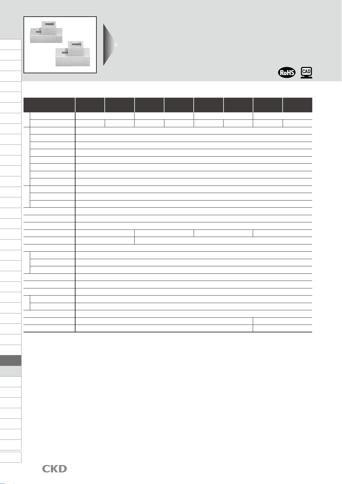
Flow sensor for compressed air PF Series
Strongly supports energy-saving activitiesStrongly supports energy-saving activities
Integrating flow and instantaneous flow rate displays can be
switched with a single operation
.
Correction of pressure/temperature is not required.
·
No need for pressure correction = Due to the mass detection
method used, there is no effect due to pressure change.
Hence, pressure correction is not required.
Displays the flow rate converted to atmospheric pressure (1 atm).
·
No need for temperature correction = Fluid temperature
is detected by the platinum thin film temperature sensor,
and is always displayed after being converted to flow
rate at 0°C.
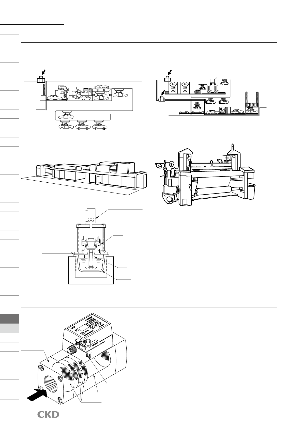
·Maintenance and measurement of air quality
available in one unit.
·Piping space/piping processes
can be reduced.
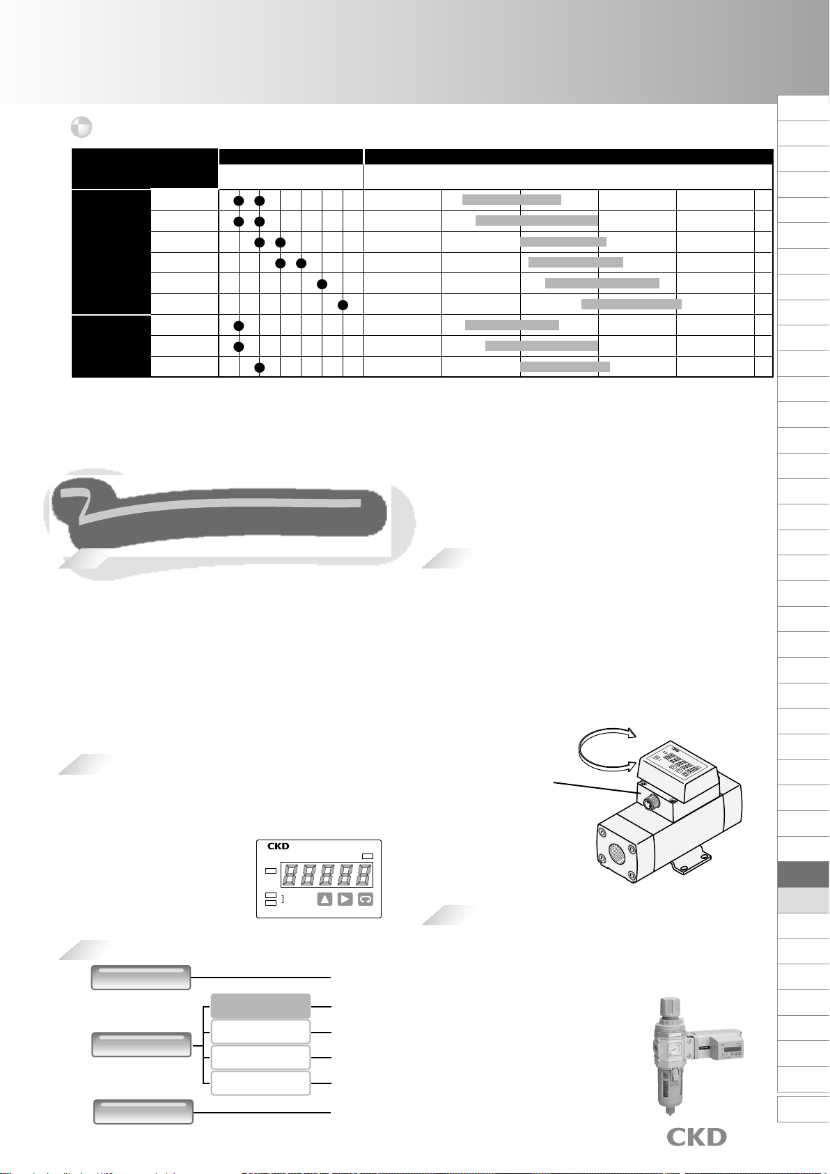
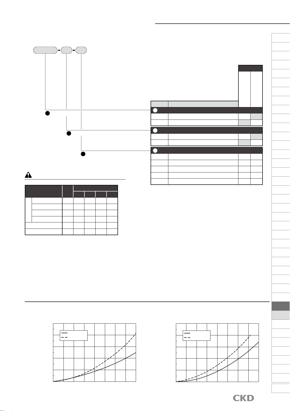
3/8
(10)
1/2
(15)
3/4
(20)
1
(25)
11/2
(40)
Port size Rc
Module
Standard
PFU1000F
PFU2000F
PFU500F
PF16000F
PF8000F
PF4000F
PF2000F
PF1000F
PF500F
2
(50)
0 10 100 1000 10000 100000
25 500
50 1000
100 2000
200 4000
400 8000
800 16000
25 500
50 1000
100 2000
Flow rate range L/min(normal)
Model
Series
●
Secure design that is hard to break even with drain (water drops)
(double the environment-resistance compared to conventional products)
·Improved water resistance by applying
a special coating to the platinum thin-film sensor.
·Overheating of the sensor element is prevented
by a protection circuit.
Reliable
Easy to use
Easily visible LED is used. Integrating flow 5-digit display.
High performance
Digital direct-reading, correction not needed
The display and sensor are housed in one compact body.
A wide range of output variations
Filter and regulator are integrated
into a unit by modular design
(PFU500F,PFU1000F,PFU2000F)
Unrestricted installation
Heavy duty design
Degree of protection IP64 equivalent
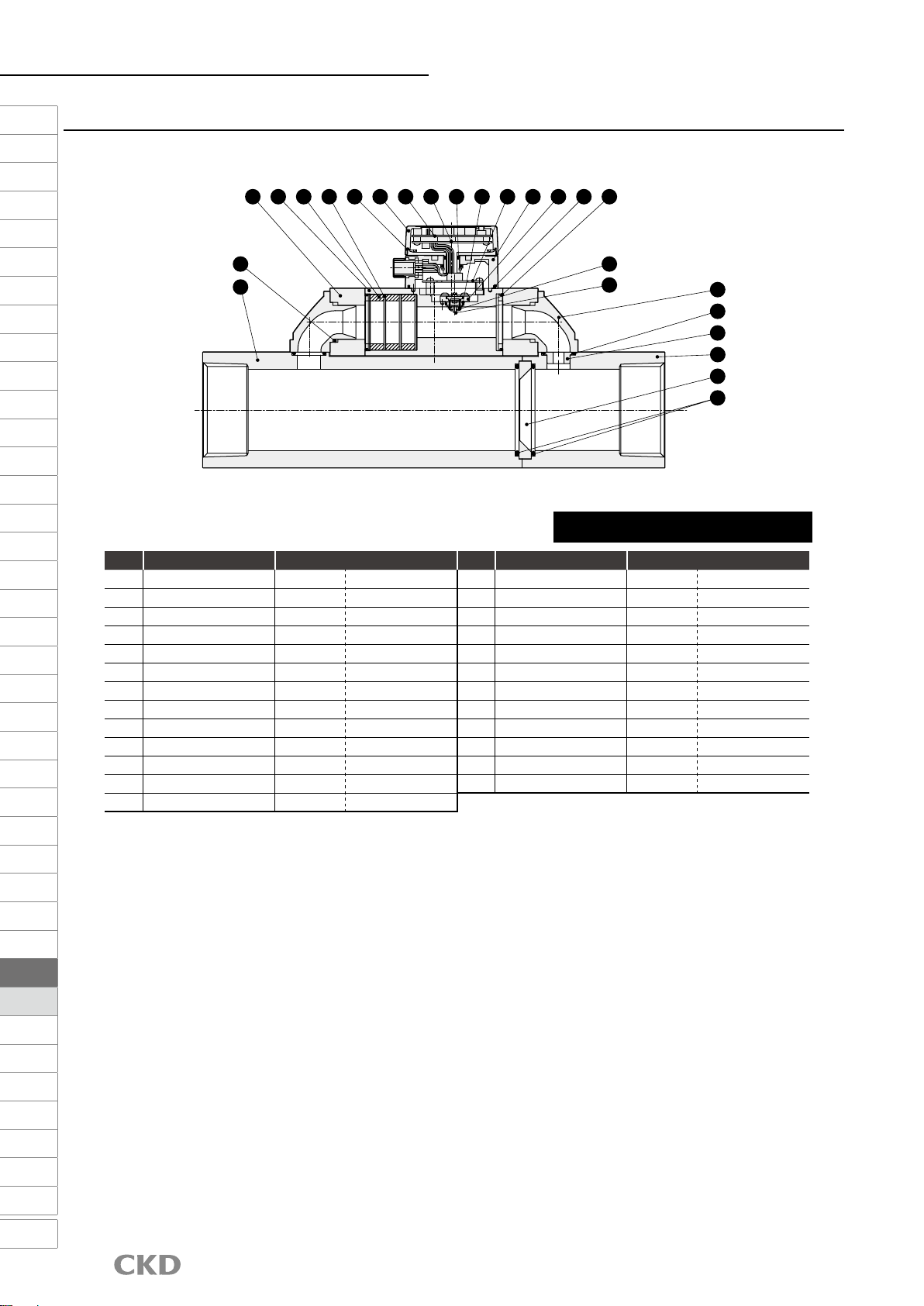
Flow distribution is constant
Flow rate distribution leans towards the outer circumferential direction
due to the elbow.
Rectifier Sensor
Air
High precision of practical precision ±3% F.S.
Pressure loss 0.005 MPa (primary pressure: 0.7 MPa)
is realized
*1
By laminating the rectification filter,
pressure loss is reduced to 0.005 MPa.
(*1: Applicable models only)
Straight piping section not required *2
Thanks to the rectifier, there is no impact even if the elbow and
T-shaped socket are piped just before the sensor.
(*2: Excluding PF8000/PF16000F)
With no need for correction, practical precision ±3% F.S. is realized at
temperature 0 to 40°C and pressure 0.1 to 1.0 MPa.
■Pipes can be installed in any orientation, vertical,
horizontal, etc.
·
The display unit can be rotated up to 270° as desired.
·Connector wires can be drawn out along the piping
and do not occupy space.
·Connector wires can be drawn from either IN or OUT
side by rotating the connector case 180°.
OUT
TOTAL
H
L
FLOW SENSOR PF SERIES
FLUEREX
L/min(normal)
Connector case
FLUEREX
L/min
PF SERIES
FLOWSENSOR
TOTAL
OUT
H
L
Analog output
Pulse output
4 to 20 mADC
0 to 5 VDC
1 to 5 VDC
0 to 10 VDC
Switch output Standard
Standard
Option
Option
Option
Option
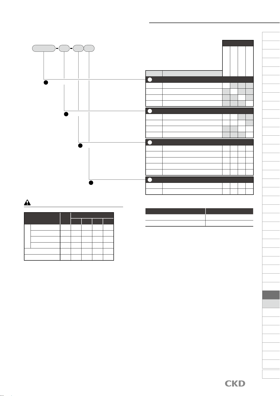
●
Measure the status of flow rate
●
Consider countermeasures
Plan
Grasp the current situation
Do
Implement measures
Action
Correction/continuation
Check
Effect confirmation
●
Measurement with flow rate sensor
●
Cost conversion is possible using integrating function
●
Standardization of equipment/line consumption
●
Application in other lines
●
Stop the air pressure supply during non-operation
●Blow time reduction
●
Application of energy saving nozzle
●Lower pressure
Very useful in grasping the current situation and confirming the effect of energy
It can be safely used even in harsh environments
such as dust and water splashing from all directions.
F.R.L
F(Filtr)
R(Reg)
L(Lub)
PresSW
Shutoff
SlowStart
FlmResistFR
Oil-ProhR
MedPresFR
No Cu/
PTFE FRL
Outdrs FR
F.R.L
(Related)
CompFRL
LgFRL
PrecsR
VacF/R
Clean FR
ElecPneuR
AirBoost
SpdContr
Silncr
CheckV/
other
Jnt/tube
AirUnt
PrecsCompn
Mech/
ElecPresSw
ContactSW
AirSens
PresSW
Cool
AirFloSens/
Contr
WaterRtSens
TotAirSys
(Total Air)
TotAirSys
(Gamma)
RefrDry
DesicDry
HiPolymDry
MainFiltr
Dischrg
etc
Ending
1368