- 2 -
Warning / cautions to secure safety
●Safety cautions are ranked by the safety cautions as
[dan er] [warnin ] [caution] in this section.
●Workin fluid, Workin environment
●Installation
●Wirin
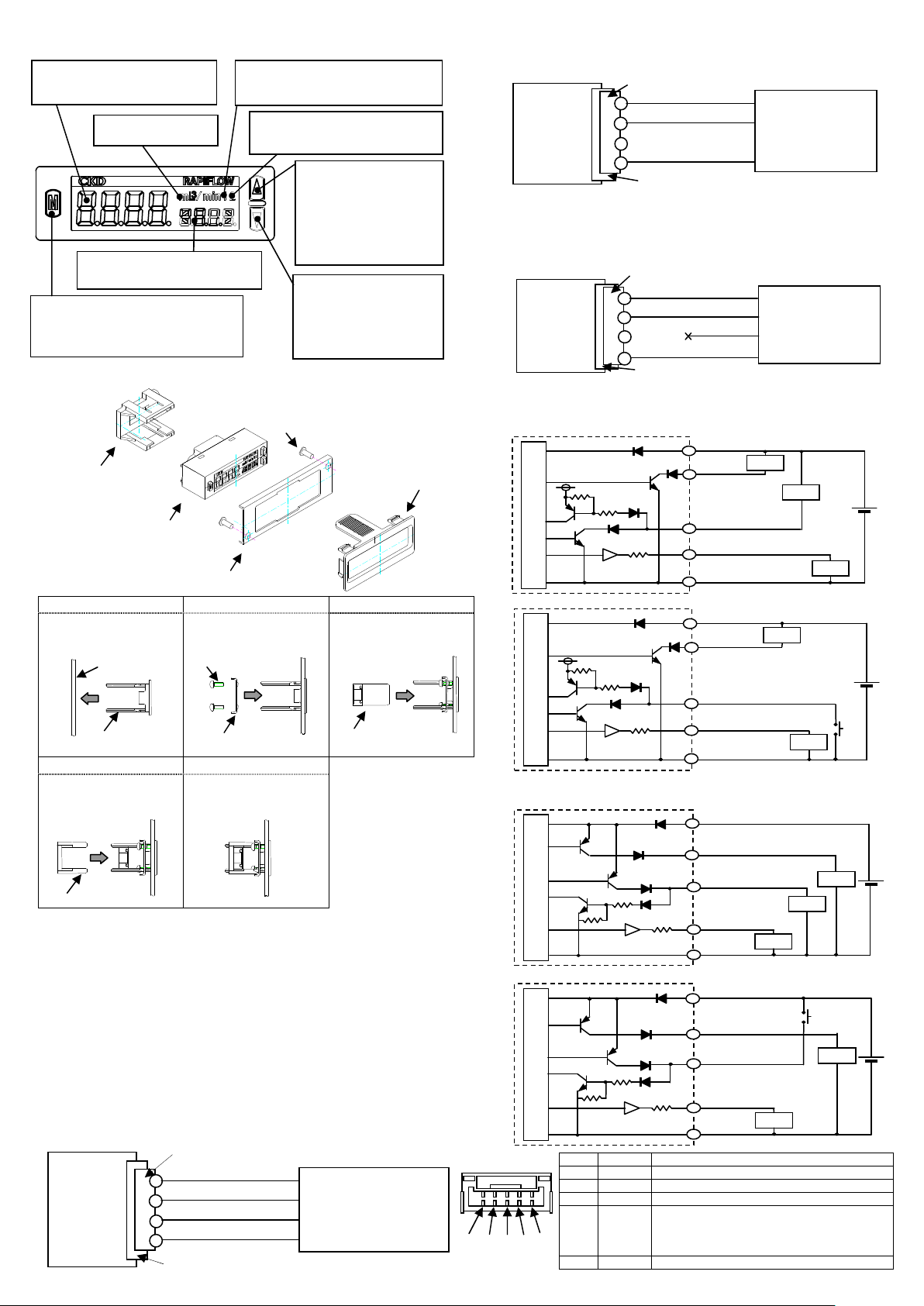
e-con SUMITOMO 3M Wire Mount plu 37104-3122-000FL
●Usa e & maintenance
●The input si nal of the separation indicator is only for (1 to 5V).
When the sensor of other output specifications is connected,
there is a possibility of dama in it.
●For wirin , stop control unit/machinery and equipment, and turn
off the power supply.
●This product and wirin must be installed as far away as possible
from noise source such as stron electric line, etc. Take other
countermeasures for a sur e on the power supply line.
●Do not short-circuit a load, or causin dama e or burn.
●Line color must be checked when wirin . Check the wirin color
with handlin precaution, since improper wire connection may
result in dama e, failure or malfunction of the sensor.
●The flow rate of this product is measured by mass flow not
depended with temperature and pressure. Unit is L/min where
mass flow is converted to volumetric flow at 20 °C and 1
atmospheric pressure (101kPa).
●Please confirm the specification of the sensor used.
●The product can not be used as a business mater. Not
conformed to the Measurement Law, do not use the product for
the commercial purpose. Use the product as an industrial
sensor.
●Do not use the product in an environment containin corrosive
as such as salphur dioxide, etc.
●Use the product within the ambient and fluid temperature ran es
0 to 50 °C. Even in the specified temperature ran e, do not use
the product where ambient and fluid temperatures will chan e
suddenly, and form dew condensations.
●The protective structure of this product is equivalent to IP40. Do
not install the product where moisture, salt, dust or swarf is
contained, or where pressurized, or depressurized, neither.
When a dan erous situation may occur, or when there is hi h
ur ency to a warnin leadin to fatal or serious injuries, if handlin
is mistaken.
When a dan erous situation may occur if handlin is mistaken,
leadin to fatal or serious injuries.
When a dan erous situation may occur if handlin is mistaken,
leadin to minor injuries or physical dama es.
Danger
●A flammable fluid must not be used.
●Do not use the product in flammable as environment. Since
explosion-protection is not taken, explosion or fire may be
caused.
●The display part uses the LCD. The display becomes difficult to
see for the view an le.
●This product can be installed with any attitude; vertical,
horizontal, ri ht or left.
●When you install the panel mountin please fix by the ti htenin
torque of 0.06N・m when you fix the panel bessel suppression.
●Power supply volta e and outputs must be used with the
specified volta e. Applyin the volta e more than specified
volta e may cause malfunction, dama e of sensor, electric
shock or fire.
Do not apply load more than the rated output. Dama e or fire of
the output may be caused.
●Output accuracy is affected by self exoer ics caused by
ener izin other than temperature characteristics. When usin ,
stand-by time (5 minutes and over after ener izin ) must be
provided.
●For self-dia nosis, this product does not conduct flow rate
detectin switch operation for proximate 2 seconds immediately
after ener ized. Make a control circuit and pro rams to i nore
si nals for approximate 2 seconds after ener ized.
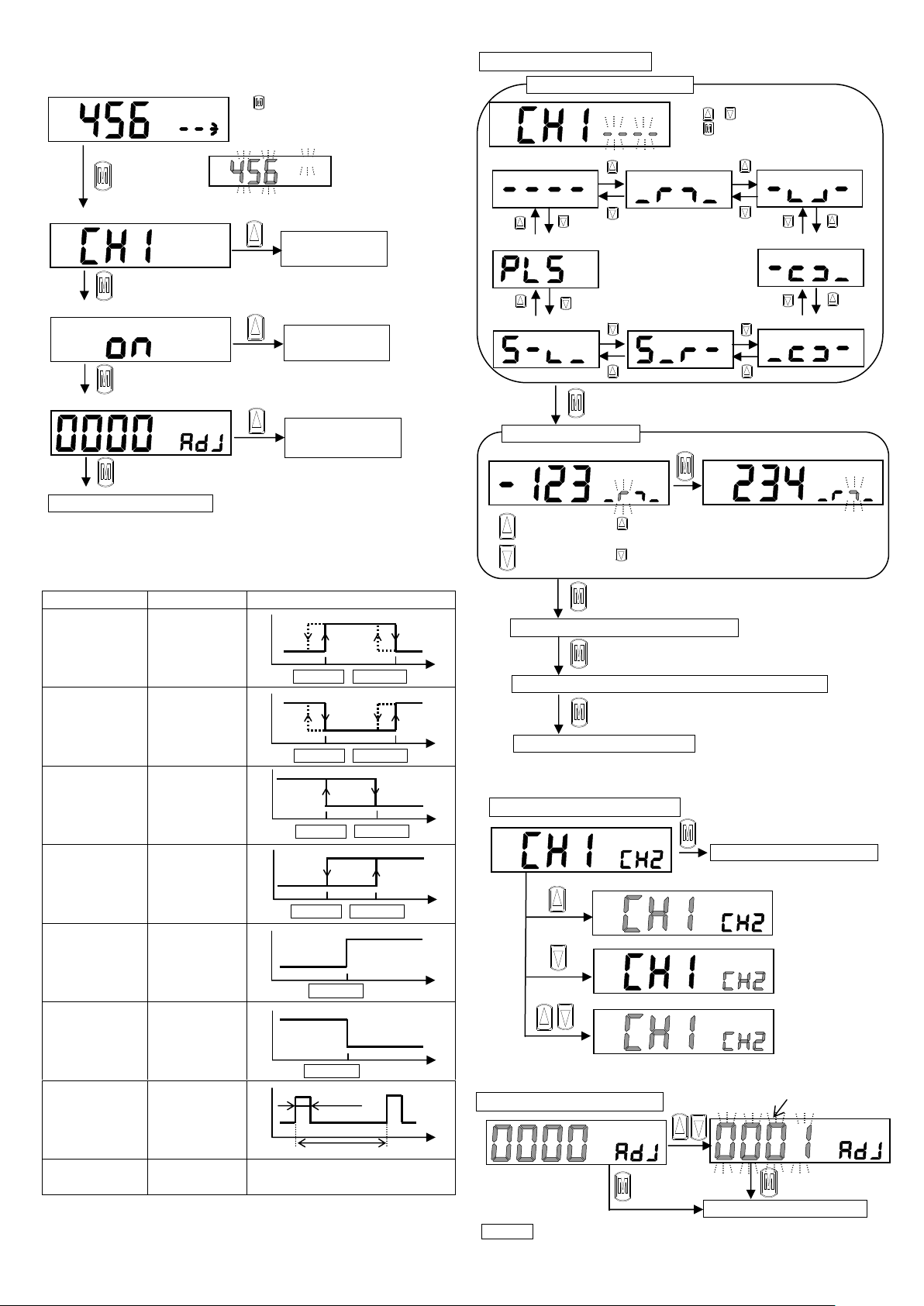
●When the FSM2 separation display type is connected, and the
power supply is turned on, the model is automatically
reco nized. However, please set the model by the manual
operation when mis-reco nizin it by the noise etc. When other
sensors are connected, the automatic reco nition cannot be
done. In this case, please set it by the manual operation.
●When chan in set-points of the output, stop the equip-ment,
then chan e the set-points, or an accident may occur.
●Disassembly and modification must not be done or causin a
failure.
●When an error occurs durin operation, turn off power supply
immediately, and terminate the operation, and contact to the
sales office.
●The material of case is resin. Solvent/alcohol/cleaner, etc., must
not be used to remove contamination, etc., or causin a resin to
be corroded. Wipe weakened neutral deter ent with ti htly
squeezed waste cloth, etc.
●When out of flow rate ran e, analo output will be provided. [Hi]
or [Lo] will be displayed. However, accuracy is not uaranteed.
●The display part use the liquid crystal. Do not push the display
part., or causin dama e.
Warning
Danger
Warning
Danger
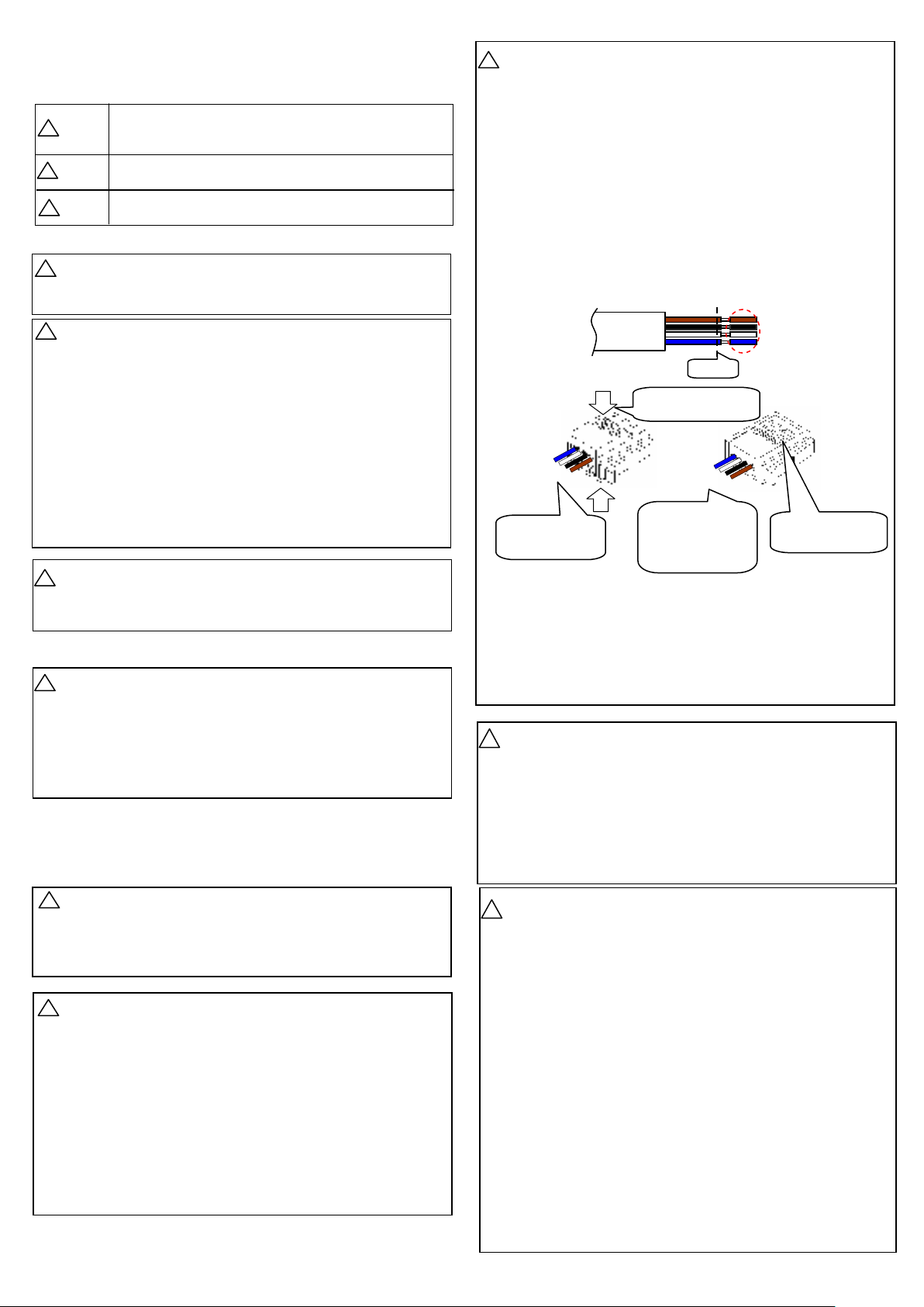
●After the connectors are inserted, lay the connector covers over
the connectors.
●Make sure that stress by forcible bend of pullin is not applies
directly to the sensor cable joint.
●Please connect it by E-CON connector appended to this
product.
●Please use connectin the e-CON connector after cuttin the
half strip part. Please insert the electric wire in the interior of the
connector when you connect the e-CON connector, and please
clamp surely with a tool such as pliers. The removal of the
cover of the electric wire is unnecessary. Please confirm the
color and the number when you connect it, and please do not
make a mistake. The faulty wirin destroys the sensor and the
separation indicator, and causes the breakdown and the
malfunction.
●This product can be connected with the FSM series and the
WFK3000 series of the frow sensor of our company. However,
in this case, the automatic model settin function cannot be
used. Please set the model with the manual. [Please refer to
pa e 8.]
Warning
!
Caution
!
Cable
[1]
Brown
Black
White
Blue
Please insert the
electric wire in the
interior.
Brown
Black
White
Blue
It is not necessary to
make a mistake in
the color order.
1-Brown, 2-Black
3-White, 4-Blue
[2] It is a pliers weldin
with pressure.
Please match this
number and the