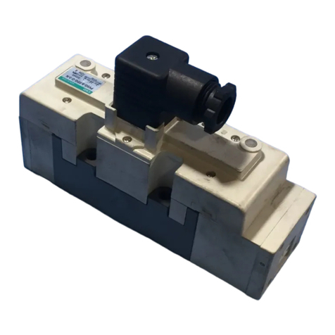
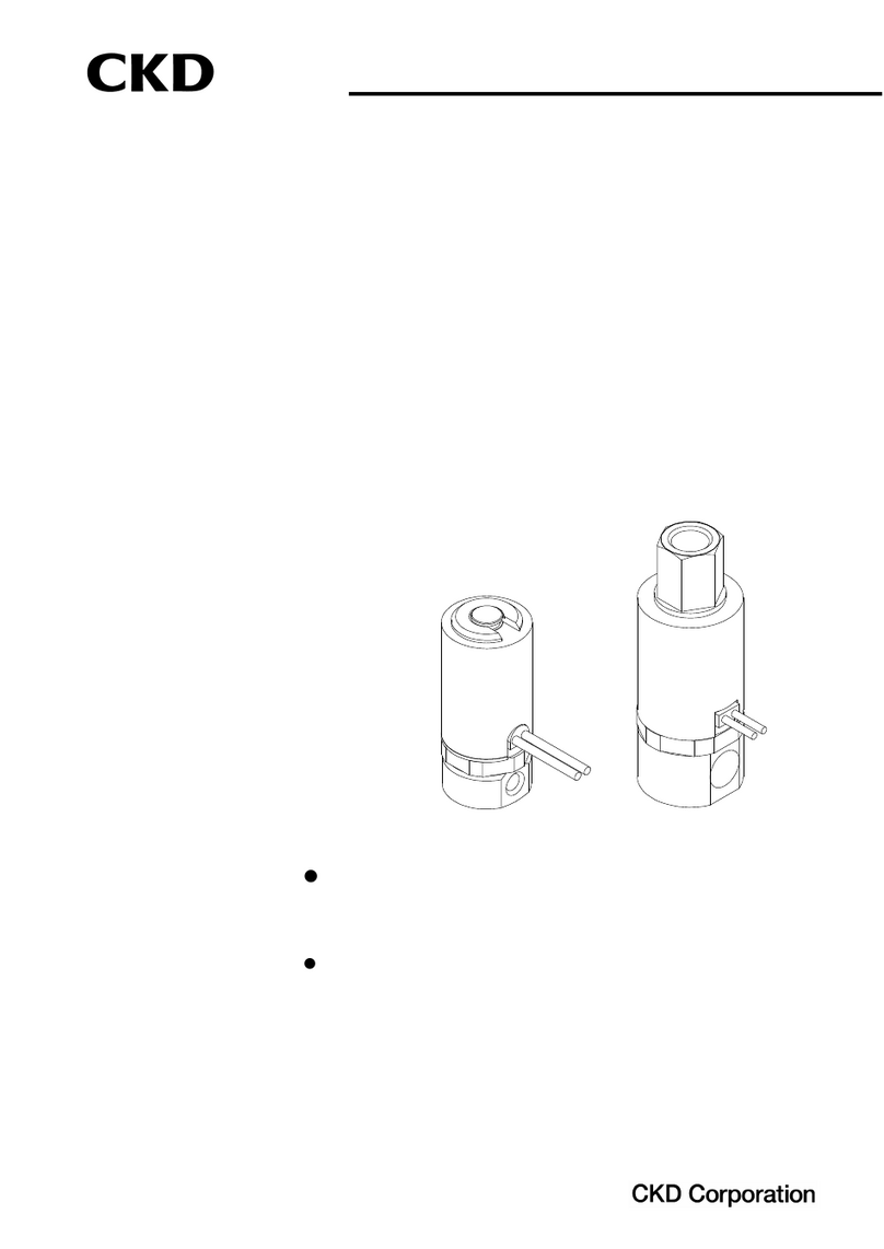
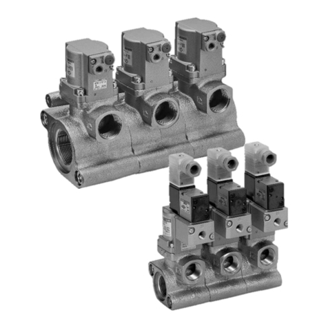
CKD GHV Series User manual

SM-50767-A
INSTRUCTION MANUAL
Gas Combustion
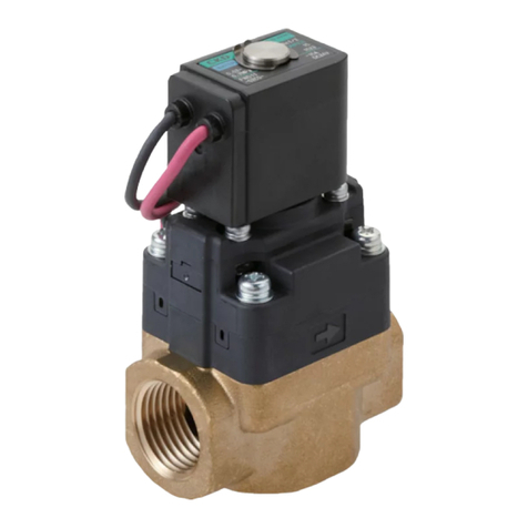
Combination Valve
G V Series
● Read this manual carefully and thoroughly
before using this product.
● Pay extra attention to the instructions
concerning safety.
● After reading this manual, keep it in a safe and
convenient place.

SM-50767-A
- 2 -
Safety precautions
All customers designing and manufacturing a device which uses CKD products have the
responsibility to, and are expected to, manufacture a device that is safe by checking that the safety of
the system operated by the following components is secured: the device mechanism, the gas
combustion equipment circuit, and the electrical control that controls these components
It is important to select, operate, handle, and maintain CKD products appropriately to ensure that
each CKD product is used safely
Please observe all warnings and precautions for each CKD product to ensure the safety of not only
the CKD products but also your device containing CKD products
1. This product has been designed and manufactured as a component for industrial use gas
combustion equipment. It must only be handled by persons with sufficient relevant
knowledge and experience.
2. se this product within its specifications.
This product must be used within its stated specifications Do not attempt to alter or modify the product
Moreover, this product is intended to be used as a component for industrial use gas combustion equipment It is not
intended for use outdoors or in applications listed below (However, this product may be used under some unintended
conditions if the customer consults CKD prior to use, understands and agrees to the product specifications, and
provides safety measures that avoid risks in the event of failures )
(1) Applications that require safety which include nuclear power applications, railroad systems, aviation systems,
ships, vehicles, medical equipment, any equipment or application that involves direct contact with food and
beverage, amusement equipment, emergency shutoff circuits, press machines, brake circuits, and safeguards
(2) Applications where serious risks to human life and/or property are expected and safety is especially required
3. Observe all applicable organization standards and regulations to ensure safety in device
design and control.
Applicable organization standards and regulations include:
- JIS B 8415, General Safety Code for Industrial Combustion Furnaces
- Safety Technology Index for Industrial Gas Combustion Equipment (The Japan Gas Association)
- Safety Technology Index for Gas Boiler Combustion Equipment (The Japan Gas Association)
- High Pressure Gas Safety Law, Occupational Safety and Health Act, and other rules, organization standards, and
regulations concerning safety
4. Do not install or use this product or remove any equipment until safety is confirmed.
(1) Conduct inspection and services on machines and devices after safety of all systems related to this product is
confirmed
(2) Handle with care as there may be hot surfaces and hot parts even after operation has stopped
(3) Before inspecting or servicing this product, stop supplying gas and turn off power to the applicable equipment
Be careful of leaks
5. Provide overcurrent protection device.
Provide overcurrent protection device (such as a molded case circuit breaker and circuit protector) and wire the
operating power source according to JIS B 9960-1: 2008, Safety of Machinery – Electrical Equipment of Machines –
Part 1: General Requirements
6. Observe all safety instructions in the pages that follow to prevent accidents.
WARNING
SM-50767-A
- -
■ In this manual, safety instructions are ranked as "DANGER", "WARNING", or "CAUTION"
DANGER indicates a hazardous situation which, if not avoided, may result in fatal
or serious injury, and there is a high degree of emergency (urgency) to a warning
WARNING indicates a hazardous situation which, if not avoided, may result in
fatal or serious injury
CAUTION indicates a hazardous situation which, if not avoided, may result in
only minor injury or property damage
Please note that even some instructions labeled as “CAUTION” may lead to serious results
depending on the situation In any case, make sure to observe all instructions as they contain
important information
Important notes on warranty
• Term of warranty
The product specified herein is warranted for one (1) year from the date on which the product is
delivered to the location designated by the customer
• Scope of warranty
If the product becomes defective for reasons attributable to CKD within the above term of
warranty, CKD will promptly provide replacement for the defective product or part thereof or
repair the defective product at one of CKD’s facilities free of charge
However, following defects are excluded from this warranty:
(1) Defects due to use of the product under conditions and in environments not conforming to
those stated in this manual
(2) Defects due to misuse, including abuse and neglect, and improper maintenance of the product
(3) Defects due to reasons other than the delivered product
(4) Defects due to use for which the product is not intended
(5) Defects due to modifications and alterations to structure, performance, and/or specifications
without permission from CKD and repairs not authorized by CKD
(6) Defects that could have been avoided if the customer’s equipment, into which the product is
incorporated, had functions, structure, etc generally provided as an accepted standard in the
industry
(7) Defects due to reasons unforeseen at the level of technology available at the time of delivery
(8) Defects due to natural disasters, accidents, or any other causes beyond control of CKD
The warranty set forth above covers only the delivered product itself and does not cover any
incidental or consequential damages due to failure of the delivered product
• Determination of compatibility
It is the responsibility of the customer to determine whether the CKD product is compatible with
the system, machinery, and/or device with which the product is to be used
DANGER
WARNING
CAUTION

SM-50767-A
- 4 -
Contents
Page
1 Inspections upon delivery
1-1 Product appearance 5
1-2 Nameplate information 5
1-3 Product storage 5
2 Installation
2-1 Installation environment 6
2-2 Mounting 6
2-3 Piping 7
2-4 Wiring 8
3 Inspections before operation
3-1 Conformity with specifications 11
3-2 Actuation 11
3-3 Leakage 11
3-4 Heat generation of coil 12
4 Proper operation
4-1 Precautions 13
4-2 Pressure adjustment 14
4-3 Start gas adjustment 15
5 Periodic inspection
16
6 Troubleshooting
17
7 Product specification and model number
7-1 Product application 18
7-2 Main features 18
7-3 Product specification 19
7-4 Model number representation 19
7-5 Closed position indicator switch specification 20
8 Internal structure and outside dimensions
8-1 Internal structure 21
8-2 Outside dimensions 22
9 Reference materials
9-1 Flow characteristics 24
9-2 Flow rate conversion factor 24

SM-50767-A
- 5 -
1 Inspections upon delivery
1-1 Product appearance
Check the product’s exterior appearance for any abnormality by thoroughly inspecting the product for any
damage or loose bolts that may have occurred during transportation
1-2 Nameplate information
Check the model number, specification, and any other information printed on the product nameplate
Model number
Rated voltage (VAC) Apparent power (VA)
Serial number Nominal diameter (Rp)
Ambient temperature (°C) Other information
Maximum working pressure (kPa)
1-3 Product storage
If the product is not used immediately upon delivery, avoid storing the product in hot, humid locations
Moreover, to protect the product, store it in as much of the original packaging and condition as possible
1
2
4
5
6
7
8

SM-50767-A
- 6 -
2 Installation
2-1 Installation environment
a) Do not use this product in the presence of corrosive gas or in an
atmosphere that may affect the material of construction
b) Do not install this product in locations subject to vibration and shock
c) Do not expose this product to direct sunlight, rain, and wind
2-2 Mounting
d) Read and understand the manual fully before mounting the product
e) Hold the body of the product when handling and mounting
f) After mounting the product, make sure it is mounted properly by
checking for leaks
2-2-1 Handling
Do not drop or step on the product
2-2-2 Mounting orientation
This product can be mounted on the piping at any position from upright (coil in the up position) to 90° from
upright on a horizontal axis (coil lies horizontally) with respect to the piping connection or on vertical
piping The coil must not lie below the horizontal axis with respect to the piping connection
Acceptable orientation
Vertical piping
Prohibited orientation
(Coil lies below horizontal axis with
respect to piping connection)
Horizontal
position
NO
NO
Upright position
Horizontal
position
NO
Coil
WARNING
WARNING

SM-50767-A
- 7 -
2-2-3 Flow direction
Mount the product so the direction of the arrow on the product corresponds to the direction of gas flow
2-2-4 Filter installation
Install a filter upstream of the product to remove dust and other foreign matter
2-2-5 Space around the product
Provide an access space of about 20 cm wide around the product for inspection and maintenance
2-3 Piping
2-3-1 Air flushing
Before piping the product, flush pipes with air to remove machining dust and other foreign matter
2-3-2 Application of sealant to pipe threads
Before connecting the pipes, apply a sealant designated by the city gas manufacturer to the pipe threads
starting with the second thread from the end of the pipe Do not apply too much Also, make sure the
sealant does not get into the pipes when applying it
Filter
Gas Gas

SM-50767-A
- 8 -
2-3-3 Length of pipe thread
For the gas pipe thread length, observe the effective thread length Too long or too short may result in
damage and leakage Make sure to file off about one-half pitch of thread from the end
2-3-4 Mounting and piping
Before mounting this product on the pipes, attach flanges to pipe ends and align the flanges in a straight
line Use the O-rings provided with the product Make sure the flanges cover the O-rings entirely and
tighten all flange bolts at one torque level in a sequence as shown on the left to avoid uneven tightening
2-3-5 Breather hole (for GHV-G)
Breather hole located at lower part of this product is provided with an Rp 1/4 connection for ventilation in
case of failures such as damage to the diaphragm Vent properly and make sure the breather hole does not
become blocked
2-4 Wiring
2-4-1 Electric wire
Use an electric wire with a cross-sectional area of at least 0 75 mm
2
For terminal block connection, crimp a
spade tongue crimp terminal or a ring tongue crimp terminal (for M3 screws) to the wire
At least 0.75 mm
2
Breather hole
(Rp 1/4)
Align in a straight line
Tightening torque:
15±1 N·m

SM-50767-A
- 9 -
2-4-2 Fuse installation
When installing a fuse in the power circuit, make sure to use a fuse of appropriate capacity
2-4-3 Operating power source connection
(1) When connecting the power source, properly connect the high voltage and ground wiring as shown below
(2) Wiring method
[Connecting to DIN terminal]
1) Strip away lead sheath and pass leads through cap, washer, gasket, and DIN terminal box case
2) Crimp the crimp terminals (for M3 screws) onto leads Secure the crimp terminals to the terminal
block terminals specified for each voltage (see below) Terminal screw tightening torque is 0 5 N·m
3) Attach terminal box gasket and terminal block to DIN terminal block on the product Place DIN
terminal box case over them and secure with the setscrew Setscrew tightening torque is 0 5 N·m
4) Screw on the cap to secure the cord
[Terminal block wiring]
Setscrew
DIN terminal box case
Gasket
Washer
Cap
Cabtire cord
Terminal block
DIN terminal block
Terminal box gasket
Crimp terminal
Terminal screw
100 VAC 200 VAC
Ground
Ground
Connect to 1 and 2
Connect to 2 and
High voltage
High voltage
Ground
Ground
Combustion
safety
device
Combustion
safety
device

SM-50767-A
- 10 -
Once wiring is complete, turning on the power actuates
the 2 solenoid valves constituting the product
Whether or not the power is on can be determined from
the LED lights on the electrical part of the product
2-4-4 Wiring of closed position indicator switch (Option: E)
[Connecting to DIN terminal]
1) Strip away lead sheath and pass leads through cap, washer, gasket, and DIN terminal box case
2) Crimp the crimp terminals (for M3 screws) onto leads Secure the crimped terminals to the terminal
block Terminal screw tightening torque is 0 5 N·m
3) Attach terminal box gasket and terminal block to the exterior cover assembly Place DIN terminal
box case over them and secure with the setscrew Setscrew tightening torque is 0 5 N·m
4) Secure the cord with the cap
[Precautions for connecting the wires]
· Use a cabtire cord with an outer diameter of ø6 mm to ø10 mm and a nominal cross-sectional
area of 0 75 mm
2
to 1 5 mm
2
· Connect the ground terminal to ground to prevent electrical shock in the event of a current leak
· To change the orientation of the cord outlet, remove the terminal block from the case, rotate it
by 90° for each orientation, and return it to the case
Circuit diagram:
Diagram below indicates valve is closed.
LED lights
Micro switch
DIN terminal
Terminal block
Setscrew
Terminal box gasket
DIN terminal box case
Terminal block
Ground terminal
Exterior cover assembly
Terminals
Crimp terminal
Cabtire cord
Gasket
Cap
Washer
screw
Terminal

SM-50767-A
- 11 -
2-4-5 Surge voltage prevention
When connecting the product and inductive load (such as motor, relays) in parallel, wire them as shown
below so the surge voltage is not applied to the product
3 Inspections before operation
3-1 Conformity with the specifications
Make sure operating conditions such as voltage and gas pressure are in conformity with the specifications
on the product nameplate
· Power voltage
Make sure the power voltage is within -15% to +10% of the rated voltage
· Working pressure
Make sure the inlet pressure is within the primary working pressure range
· Ambient temperature
Make sure the installation site’s ambient temperature is within the allowable ambient temperature range
3-2 Actuation
Apply operating power to this product, and make sure the valves actuate and the valves return to the
original position when the power is turned off
3-3 Leakage
· External leakage
Use a gas leak detector or soap water to make sure there is no external leakage from the connections and
from the product
Outside allowable range
Within allowable range
Outside allowable range

SM-50767-A
- 12 -
· Internal leakage
Procedure 1: Test for leakage of gas pipes
a) Close valve 2 Apply power to the product With the product in the open position, apply supply gas
pressure Close valve 1
b) Measure the pressure within the pipes using a water column gauge Leave it for more than 5 minutes
and check for leakage
c) If there is leakage, inspect the connections and wherever leak is likely occurring using a leak detector
or soap water
Procedure 2: Test for internal leakage of primary-side valve
a) Turn off power to the product so it is in the closed position Open valve 1 Apply normal operating
pressure from the upstream side of primary-side valve
b) Connect rubber hose to test cock 2 which leads to intermediate pressure detection port on the product
Submerge the loose end of the hose into a water-filled container, such as a beaker, by about 10 mm
Open test cock 2 and check for bubbles
Procedure 3: Test for internal leakage of secondary-side valve
a) Apply normal operating pressure between secondary-side of the product and valve 2 Make sure there
is no pressure drop
b) With the product in the closed position, connect test cocks 1 and 2 Open valve 1 Apply normal
operating pressure from the upstream side of secondary-side valve
c) Under this condition, open valve 2 After adjusting the pressure of the downstream side of the product
to atmospheric pressure, close valve 2 Connect rubber hose to test cock 3 Submerge the loose end of
the hose into a water-filled container, such as a beaker, by about 10 mm Open test cock 3 and check
for bubbles
3-4 Heat generation of coil
Beware of hot surface When the power is turned on, surface temperature rises to a high level due to coil
temperature rise (Please be assured that high surface temperature does not affect product performance )
Gas Valve 1
Test
cock 1
Water column gauge
Primary-side valve
Secondary-side valve
Product (both valves open/close simultaneously)
Valve 2
Test
cock
Graduated cylinder
Intermediate
pressure
detection
port
Test
cock 2

SM-50767-A
- 1 -
4 Proper operation
4-1 Precautions
a) This product is not for use as an emergency shutoff valve
· This product is not designed to provide safety protection, like that
provided by an emergency shutoff valve If this product is used in a
system which requires safety measures, make sure to adopt other
reliable safety measures
b) To protect against possible harm to people and equipment in case of
product failure, implement necessary measures beforehand
c) Working fluid
· Do not use fluids other those listed in the specification
· Do not use this product with fluids other than city gas, natural gas, and LPG
· Do not disassemble, repair, or modify this product
· City gas
· Natural gas
· LPG
Working fluid
·
Air
·
Inert gas
·
Gases other than combustion gas
·
Vacuum
·
Water
·
Steam
·
Oil
·
Other liquids
WARNING

SM-50767-A
- 14 -
4-2 Pressure adjustment
This feature is available only on GHV-G-
※,
“solenoid valve with built-in governor + solenoid valve” type
models
[Adjusting the pressure]
Loosen and remove the governor cap (the taller cap) Adjust pressure by turning the pressure-adjusting
screw with a flat blade screwdriver Turning the screw clockwise raises the pressure and turning it
counterclockwise reduces the pressure
[Precautions for adjusting the pressure]
· A stopper prevents the pressure-adjusting screw from being turned beyond the upper and lower
limits of the pressure adjustment range Do not try to turn the screw beyond these limits as
doing so may damage some parts and cause gas leak
· Pressure is set to maximum before shipping (However, after turning the pressure-adjusting
screw clockwise to a stop, it has been turned back a few turns to prevent damage to it )
· Pressure-adjusting screw becomes very hot during pressure adjustment Be careful to avoid
direct contact with the screw as it can cause burns
· Install a pressure gauge and check the actual pressure while adjusting pressure
· The cap (one with a red marking) next to the governor cap is attached to the product and will
not turn This cap is not relevant to pressure adjustment Do not loosen this cap If this cap is
forcibly loosened, its contents may fall out
* If this product is not used for a certain period of time after installing it in your device, the valves may not
open depending on the usage environment If this is the case, turn the pressure-adjusting screw to the
maximum set pressure and actuate the product before starting regular operation
Governor cap
Pressure-adjusting screw
Raise pressure
(Clockwise direction)
Reduce
pressure
Pressure-adjusting screw
* Pressure-adjusting screw becomes very hot.
Be careful to avoid direct contact with the screw
as it can cause burns.
* Do not loosen this cap. It is attached to the product.

SM-50767-A
- 15 -
4-3 Start gas adjustment
This feature is available only on GHV-L-
※,
“solenoid valve + solenoid valve (slow open)” type models
[Adjusting the start gas]
To adjust the start gas, turn the damper assembly as shown below to change the flow rate of start gas
Procedure
(1) Loosen the slotted flat fillister head machine screw
(2) Turn the damper assembly and adjust the flow rate of start gas
Turning the damper assembly counterclockwise increases start gas
(Turning it clockwise decreases start gas )
(3) After adjusting the start gas, tighten the slotted flat fillister head machine screw
* The start gas flow rate adjustment range is 0% to 70% of maximum flow rate
[Precautions for adjusting the start gas]
· Start gas flow rate is set to 0% before shipping
· Do not remove the slotted flat fillister head machine screw Only loosen it
Do not loosen other screws (heads painted in red)
· Damper assembly is allowed to be turned to a position in between the position at shipment and a
position that corresponds to about 3 turns in counterclockwise direction (from the position at
shipment) Turning the damper assembly outside of this range and applying excessive force may
damage internal parts and obstruct adjustment
Slotted flat fillister head machine screw
Decrease
flow
Damper
assembly
Screws with red paint ( screws)
(Do not loosen them.)
Increase flow
(Counterclockwise
direction)
Slotted flat fillister
head machine screw
Start gas adjustment range:
0% to 70% of maximum flow rate
Maximum flow rate
Time
Flow
rate
Start gas
Start gas at shipment (0%)

SM-50767-A
- 16 -
5 Periodic inspection
Do not disassemble, repair, or modify this product
Conduct actuation and leakage tests at least once a year (refer to sections 3-2 and 3-3) For repairs in case
of abnormal actuation, contact the dealer from whom you made your purchase or your nearest CKD agent
Conduct periodic inspections according to the periodic inspection procedures for safety shutoff valves
given in safety standards such as those listed below
Published by The Japan Gas Association
“Safety Technology Index for Industrial Gas Combustion Equipment”
“Safety Technology Index for Gas Boiler Combustion Equipment”
WARNING

SM-50767-A
- 17 -
6 Troubleshooting
Cause of the problem and corrective action
Problem
Cause Investigation Corrective action
a. Operating power
circuit has failed
Measure voltage at terminal block
inside DIN terminal box.
Allowable voltage range:
-15% to +10% of rated voltage.
Ex: For 100 VAC, allowable range
is 85 VAC to 110 VAC.
If measured voltage is not
within the range specified in
left column, inspect and
repair the power circuit.
b. Valve disc is stuck
Remove combination valve from
piping, turn on power, and check
whether or not the valve disc
rises.
Turn pressure-adjusting
screw clockwise to the
maximum and turn on
power.
1. Does not open
c. Foreign matter is
caught between
internal sliding parts
None
(Do not disassemble the product.)
Contact the dealer from
whom you made your
purchase or your nearest
CKD agent.
a. Control electric circuit
has failed
Measure voltage at terminal block
inside DIN terminal box.
If voltage is applied, inspect
and repair the electric
circuit.
2. Does not close
b. Foreign matter is
caught between
internal sliding parts
None
(Do not disassemble the product.)
Contact the dealer from
whom you made your
purchase or your nearest
CKD agent.
a. Pipe connection seal
has failed
Check for leaks from pipe
connections.
Repair the pipe connection
seal.
. Leaks externally
b. Flange seal has failed
Check for leaks from flanges.
Check for loose bolts.
Check for any damage to O-ring
and foreign matter attached to
O-ring.
Replace O-ring.
Tighten bolts.
Remove foreign matter.
4. Leaks internally
a. Foreign matter has
adhered to valve disc
or valve seat, or they
are damaged
None
(Do not disassemble the product.)
Contact the dealer from
whom you made your
purchase or your nearest
CKD agent.
5. Flow rate is low
a. Strainer is clogged
Remove combination valve from
piping and check the condition of
strainer located at back of IN-side
port.
Remove flange, and either
clean or replace the filter.
a. Valve disc is stuck
Remove combination valve from
piping, turn on power, and check
whether or not the valve disc
rises.
Turn pressure-adjusting
screw clockwise to the
maximum and turn on
power.
6. Does not adjust
pressure
(GHV-G)
b. Primary-side pressure
has dropped
Check whether or not primary-side
pressure is higher than set
pressure.
Set primary-side pressure
so that it is higher than set
pressure.
7. Does not
perform “slow
open”
(GHV-L)
a. Damper oil is leaking None
(Do not disassemble the product.)
Contact the dealer from
whom you made your
purchase or your nearest
CKD agent.

SM-50767-A
- 18 -
7 Product specification and model number
7-1 Product application
This product is used in gas passages as a gas shutoff valve and controls the ON and OFF supply of gas fuel
within industrial gas combustion equipment
(This product is not for use as an emergency shutoff valve )
An example of how this product can be applied in a gas combustion system is shown below
Example of application:
7-2 Main features
· Two solenoid valves are integrated into one compact unit for the purpose of providing a double
shutoff mechanism; a governor is also available on GHV-G models
· GHV operates under a wide range of pressures, from low to medium (working pressure range: 0 kPa
to 50 kPa)
· Secondary-side pressure can be easily adjusted and is adjustable even after installation (secondary
pressure range: 0 4 kPa to 2 0 kPa)
· Size of the ports, ranging from 25A up to 50A, can be changed just by changing the flange
connections
· There is no noise and coil burnout because the actuator is a DC drive with a built-in rectifier
· GHV is dust proof and splash proof (IP54)
Combustion monitoring device
Butterfly valve
with control motor
Pressure
switch
Air blower
Pressure
switch
GHV
Pressure
switch
UV
phototube
Pilot
burner
Burner
Ignition
transformer
Filter
Pilot system
solenoid valves
Pilot system
governor

SM-50767-A
- 19 -
7-3 Product specification
GHV-G GHV-N GHV-L
Variation Solenoid valve with built-in
governor + solenoid valve
Solenoid valve +
solenoid valve
Solenoid valve +
solenoid valve (slow open)
Description
Port size -D25
-D 2
-D40
-D50
-D25
-D 2
-D40
-D50
-D25
-D 2
-D40
-D50
Working fluid City gas/Natural gas/LPG
Working primary pressure kPa
0 to 50
Pressure adjustment range kPa
0.4 to 2.0 N/A
Flow rate
m/h (ANR)
5 4 .7
47.5
51 5 4 .7
47.5
51 5 4 .7
47.5
51
Voltage V
AC 100 AC 200
Frequency Hz
50/60 (common)
Power consumption (apparent power) VA
80
Thermal class 180 (H)
Ambient temperature °C
-15 to 70 (no freezing)
*1
-15 to 60 (no freezing)
Close operation time s
1.0 or less
Cycle rate cycles/min
10 or less 1 or less
Mounting orientation Upright with coil on top or horizontally with coil lying horizontally (vertical piping also allowed)
Connection Screw-in (Rp)
Nominal diameter 1 1 1/4
1 1/2
2 1 1 1/4
1 1/2
2 1 1 1/4
1 1/2
2
Weight kg
6.1 5.5 5.8
Proof pressure kPa
75
Open operation time s
N/A 1 or less About 10
Start gas adjustment %
N/A 0 to 70
Time to wait before turning on power
s
N/A At least 5
7-4 Model number representation
*1
-15°C to 60°C (no freezing) for models with closed position indicator switch
+10%
-15%
+10%
-15%
Natural gas specific gravity 0.65
⊿ P = 0.25 kPa
GHV
-
--
-
G
-
--
-
D40
-
--
-
E
-
--
-
AC200V
A
B
C
D
A
Variation
G
Solenoid valve with built-in governor + solenoid valve
N
Solenoid valve + solenoid valve
L
Solenoid valve + solenoid valve (slow open)
B
Port size
D00
Without flange
D25
Rp 1
D 2
Rp 1 1/4
D40
Rp 1 1/2
D50
Rp 2
C
Option
Blank
None
EWith closed position indicator switch
D
Voltage
A
C100V
100 VAC 50 Hz/60 Hz
AC200V
200 VAC 50 Hz/60 Hz

SM-50767-A
- 20 -
7-5 Closed position indicator switch specification
This section is only for GHV-
※
-E, models with closed position indicator switch (option)
Ambient temperature for models with closed position indicator switch
is -15°C to 60°C
Under low temperatures, micro switch takes longer time to operate
when the valve is open (about 5 seconds at -15°C)
Circuit diagram
Diagram above indicates valve is closed
Electrical specification
Electrical rating:
* Minimum applicable load: 5 VDC 160 mA
When the valve is closed, ON signal is generated between terminals 1 (COM) and 3 (NO);
when the valve is open, ON signal is generated between terminals 1 (COM) and 2 (NC)
Rated voltage Resistance load
125 VAC 5A
250 VAC A
CAUTION
Micro switch
DIN terminal
Terminal block
This manual suits for next models
12
Table of contents
Other CKD Control Unit manuals

CKD
CKD MN3GA1R-T6G1 User manual

CKD
CKD 4KA3 User manual

CKD
CKD PV5G Series User manual

CKD
CKD MN3GD/E1 Series User manual

CKD
CKD USB2 Series User manual

CKD
CKD MN4KB1 Series User manual

CKD
CKD 4KA2 User manual

CKD
CKD 4KA4 User manual

CKD
CKD CVE2 Series Installation and operating manual

CKD
CKD SNP Series User manual