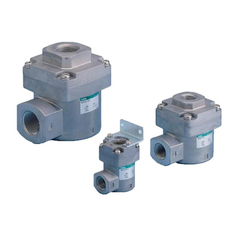
CKD QEL Series User manual

CKD Corporation
INSTRUCTION MANUAL
• Read this Instruction Manual before using the product.
• Read the safety notes carefully.
• Keep this Instruction Manual in a safe and convenient place for future reference.
SM-P00166-A
Quick Exhaust Valve With Push-in Fitting
QEL
Series

SM-P00166-A PREFACE
i
PREFACE
Thank you for purchasing CKD's”QEL Series” Quick Exhaust Valve With Push-in Fitting.
This Instruction Manual contains basic matters such as installation and usage instructions in order to
ensure optimal performance of the product. Please read this Instruction Manual thoroughly and use the
product properly.
Keep this Instruction Manual in a safe place and be careful not to lose it.
Product specifications and appearances presented in this Instruction Manual are subject to change
without notice.
• •The product is intended for users who have basic knowledge about materials, piping, electricity, and
mechanisms of pneumatic components. CKD shall not be responsible for accidents caused by
persons who selected or used the product without knowledge or sufficient training.
• •Since there are a wide variety of customer applications, it is impossible for CKD to be aware of all of
them. Depending on the application or usage, the product may not be able to exercise its full
performance or an accident may occur due to fluid, piping, or other conditions. It is the responsibility
of the customer to check the product specifications and decide how the product shall be used in
accordance with the application and usage.

SM-P00166-A SAFETY INFORMATION
ii
SAFETY INFORMATION
When designing and manufacturing any device incorporating the product, the manufacturer has an
obligation to ensure that the device is safe. To that end, make sure that the safety of the machine
mechanism of the device, the pneumatic or water control circuit, and the electric system that controls
such mechanism is ensured.
To ensure the safety of device design and control, observe organization standards, relevant laws and
regulations, which include the following:
ISO 4414, JIS B 8370, JFPS 2008 (the latest edition of each standard), the High Pressure Gas Safety
Act, the Industrial Safety and Health Act, other safety rules, organization standards, relevant laws and
regulations
In order to use our products safely, it is important to select, use, handle, and maintain the products
properly.
Observe the warnings and precautions described in this Instruction Manual to ensure device safety.
Although various safety measures have been adopted in the product, customer's improper handling may
lead to an accident. To avoid this:
Thoroughly read and understand this Instruction Manual
before using the product.
To explicitly indicate the severity and likelihood of a potential harm or damage, precautions are classified
into three categories: "DANGER", "WARNING", and "CAUTION".
DANGER Indicates an imminent hazard. Improper handling will cause death or serious
injury to people.
WARNING Indicates a potential hazard. Improper handling may cause death or serious
injury to people.
CAUTION Indicates a potential hazard. Improper handling may cause injury to people or
damage to property.
Precautions classified as "CAUTION" may still lead to serious results depending on the situation.
All precautions are equally important and must be observed.
Other general precautions and tips on using the product are indicated by the following icon.
Indicates general precautions and tips on using the product.

SM-P00166-A INDEX
iii
INDEX
PREFACE........................................................................................................................... i
SAFETY INFORMATION .................................................................................................. ii
INDEX.............................................................................................................................. iiii
1. PRODUCT.................................................................................................................. 1
1.1 How to order ....................................................................................................... 1
1.2 Specification........................................................................................................ 2
1.3 DIMENSIONS ..................................................................................................... 3
1.3.1 Type with exhaust port fitting.......................................................................... 3
1.3.2 Atmosphere release ....................................................................................... 3
1.3.3 Plug type......................................................................................................... 4
1.4 Internal structure and parts list ........................................................................... 5
1.4.1 Type with exhaust port fitting.......................................................................... 5
1.4.2 Atmosphere release ....................................................................................... 5
1.4.3 Plug type......................................................................................................... 6
2. INSTALLATION ......................................................................................................... 7
2.1 Environment........................................................................................................ 7
2.2 Unpacking ........................................................................................................... 7
2.3 Mounting ............................................................................................................. 7
2.4 Piping .................................................................................................................. 8
2.4.1 Fundamental circuit ........................................................................................ 8
2.4.2 Piping.............................................................................................................. 9
3. USAGE..................................................................................................................... 10
3.1 CAUTION.......................................................................................................... 10
4. WARRANTY PROVISIONS..................................................................................... 11
4.1 Warranty Conditions ..........................................................................................11
4.2 Warranty Period .................................................................................................11

SM-P00166-A 1. PRODUCT
1
1. PRODUCT
1.1 How to order
(A) (B)
(A) Port size (B)Option
H44 φ4 Blank Type with exhaust port fitting
H66 φ6 S Atmosphere release
44P φ4plug
66P φ6plug
Note1:For”44P” ”66P”、(B)”Blank”cannot be selected。
QEL H44 S

SM-P00166-A 1. PRODUCT
2
1.2 Specification
Model No.
Descriptions
QEL-H44 QEL-H44-S QEL-44P-S QEL-H66 QEL-H66-S QEL-66P-S
Working fluid Compressed air
Max.working pressure MPa 0.7
Min.working pressure MPa 0.1
Min.operating pressure MPa 0.05
Proof pressure(normal temperature) MPa 1.35
Ambient temperature ℃5 to 60 (no freezing)
Port size
IN φ4 φ4 φ4 φ6 φ6 φ6
OUT φ4 φ4 φ4 plug φ6 φ6 φ6 plug
EXH φ4 Atmosphere
release
Atmosphere
release φ6 Atmosphere
release
Atmosphere
release
Weight g 5.2 5.2 2.4 7.6 4.9 3.9
Mounting orientation Unrestricted
Effective cross-
sectional area
IN→OUT mm21.8 1.5 4 2.6
OUT→EXH mm21.8 1.5 4 2.6

SM-P00166-A 1. PRODUCT
3
1.3 DIMENSIONS
1.3.1 Type with exhaust port fitting
Code
Model No
φD
Tube O.D.
B L1 L2 L3 φP1 φP2 φP3 φP4 C E X Y
QEL-H44 φ4 35.2 30.5 18.8 14.1 10 9 8.4 9 11.3 11 9.8 7.8
QEL-H66 φ6 37.4 32.4 20.2 15.2 12 11 10.4 11 11.8 13 11.8 9.8
1.3.2 Atmosphere release
Code
Model No
φD
Tube O.D.
B L1 L2 φP1 φP2 φP3 C X Y
QEL-H44-S φ4 35.2 11.3 15 8.4 10 9 11.3 9.8 7.8
QEL-H66-S φ6 37.4 12.2 15 10.4 12 11 11.8 11.8 9.8

SM-P00166-A 1. PRODUCT
4
1.3.3 Plug type
Code
Model No
φD1
Tube O.D.
φD2
Port size B L1 L2 φP C H
(六角対辺)X Y
QEL-44P-S φ4 φ4 41.3 4.1 19 9 11.3 10 9.8 7.6
QEL-66P-S φ6 φ6 47.5 4.7 22 11 11.8 12 11.8 9.8

SM-P00166-A 1. PRODUCT
5
1.4 Internal structure and parts list
1.4.1 Type with exhaust port fitting
JIS SYMBOL
No Part name Material No Part name Material
1Resin body Polybutylene terephthalate 7Guide ring Brass (with electroless nickeling)
2Exhaust fitting body Polybutylene terephthalate 8Release ring Acetal resin
3Plug Brass (with electroless nickeling) 9Valving element stopper Brass (with electroless nickeling)
4Elastic sleeve Nitrile rubber 10 Valving element Hydrogenated nitrile rubber
5Lock ring Stainless steel 11 O-ring Nitrile rubber
6Lock claw Brass (with electroless nickeling)
1.4.2 Atmosphere release
JIS SYMBOL
No Part name Material No Part name Material
1Resin body Polybutylene terephthalate 6Guide ring Brass (with electroless nickeling)
2Exhaust fitting body Polybutylene terephthalate 7Release ring Acetal resin
3Elastic sleeve Nitrile rubber 8Valving element stopper Brass (with electroless nickeling)
4Lock ring Stainless steel 9Valving element Hydrogenated nitrile rubber
5Lock claw Brass (with electroless nickeling)

SM-P00166-A 1. PRODUCT
6
1.4.3 Plug type
JIS SYMBOL
No Part name Material No Part name Material
1Release ring Acetal resin 6Resin body Polybutylene terephthalate
2Guide ring Brass (with electroless nickeling) 7Valve body presser Aluminum
3Lock claw Brass (with electroless nickeling) 8Valving element Hydrogenated nitrile rubber
4Lock ring Stainless steel 9Wrecking ball Stainless steel
5Elastic sleeve Nitrile rubber

SM-P00166-A 2. INSTALLATION
7
2. INSTALLATION
2.1 Environment
Do not use the product in an environment where
• Many vibrations and shocks.
• Hot and humid.
• It is exposed to direct sunlight,rain,wind,or water.
• Do not use the product in a place where it could come in direct contact with cutting oil,coolant or
spatter,etc.
• Ozone is produced.
2.2 Unpacking
CAUTION
Do not open the packing of the product until just before piping to prevent foreign matters
from entering the product.
• Check that the model number ordered and the model number indicated on the product are the same.
• Check the exterior of the product for any damage.
2.3 Mounting
WARNING
Around the piping so that connections are not dislocated by equipment movement, vibration,
Tension, etc
• Insert the plug type securely and check that it cannot be pulled out before using. If it is not securely
inserted all the way in, it may cause a plug disconnection or air leakage.

SM-P00166-A 2. INSTALLATION
8
2.4 Piping
2.4.1 Fundamental circuit
The fundamental circuit diagram of quick exhaust valve is as per shown below.
How to speed up air cylinder exhaust
How to speed up the clutch (or brake) exhaust
Air cylinder
Quick exhaust valve Quick exhaust valve
5-port valve
Clutch (or brake)
Quick exhaust valve
3-port valve

SM-P00166-A 2. INSTALLATION
9
2.4.2 Piping
WARNING
Stop air flow and confirm that there is no residual pressure before replacing the tube.
Securely insert the tube end and make sure that the tube cannot be pulled out.
CAUTION
Make sure that there is no torsion,tension or moment load applied to the fitting or the tube.
If the tubes can move around when disconnected, bind the tubes or use a safety cover.
Flushing
Flush the pipes/tubes just before connecting the product to the pneumatic components.
Outside diameter accuracy of tubes
When using anon-CKD tube, make sure that the outer diameter tolerance of the tube satisfies the
specifications given in Table 1.
Urethane tube Nominal port size±0.15mm
Nylon tube Nominal port size±0.1mm

SM-P00166-A 3. USAGE
10
3. USAGE
3.1 CAUTION
WARNING
Always use within the product specifications.
Pressure range:0.1〜0.7MPa.
• This product is used for compressed air.Do not use this unit for other fluids.
• Check that the tubing is not worn or damaged.Tubing could collapse,rupture,or become dislocated.
• After connecting piping, check pipe connections for air leaks before supplying compressed air. Also do
not suddenly apply high pressure.
• Since the product is intended for use with compressed air, small amount of leakage to internal and
external parts that do not affect product performance is permitted.
• Do not constantly push down or apply a load onto the push ring for the push-in fitting.

SM-P00166-A 4. WARRANTY PROVISIONS
11
4. WARRANTY PROVISIONS
4.1 Warranty Conditions
Warranty coverage
If the product specified herein fails for reasons attributable to CKD within the warranty period specified
below, CKD will promptly provide a replacement for the faulty product or a part thereof or repair the faulty
product at one of CKD’s facilities free of charge.
However, following failures are excluded from this warranty:
• Failure caused by handling or use of the product under conditions and in environments not conforming
to those stated in the catalog, the Specifications, or this Instruction Manual.
• Failure caused by incorrect use such as careless handling or improper management.
• Failure not caused by the product.
• Failure caused by use not intended for the product.
• Failure caused by modifications/alterations or repairs not carried out by CKD.
• Failure that could have been avoided if the customer’s machinery or device, into which the product is
incorporated, had functions and structures generally provided in the industry.
• Failure caused by reasons unforeseen at the level of technology available at the time of delivery.
• Failure caused by acts of nature and disasters beyond control of CKD.
The warranty stated herein covers only the delivered product itself. Any loss or damage induced by
failure of the delivered product is excluded from this warranty.
Confirmation of product compatibility
It is the responsibility of the customer to confirm compatibility of the product with any system, machinery,
or device used by the customer.
Others
The terms and conditions of this warranty stipulate basic matters.
When the terms and conditions of the warranty described in individual specification drawings or the
Specifications are different from those of this warranty, the specification drawings or the Specifications
shall have a higher priority.
4.2 Warranty Period
The product is warranted for one (1) year from the date of delivery to the location specified by the
customer.
This manual suits for next models
6
Table of contents
Other CKD Control Unit manuals

CKD
CKD 3GD/E1 Series User manual

CKD
CKD M3GA/B R Series User manual

CKD
CKD 3KA1 User manual

CKD
CKD SAB A Series User manual

CKD
CKD 4KA2 User manual

CKD
CKD CVE2 Series Installation and operating manual

CKD
CKD 4KA3 User manual

CKD
CKD PV5G Series User manual

CKD
CKD MN4KB1 Series User manual
CKD
CKD SNP Series User manual