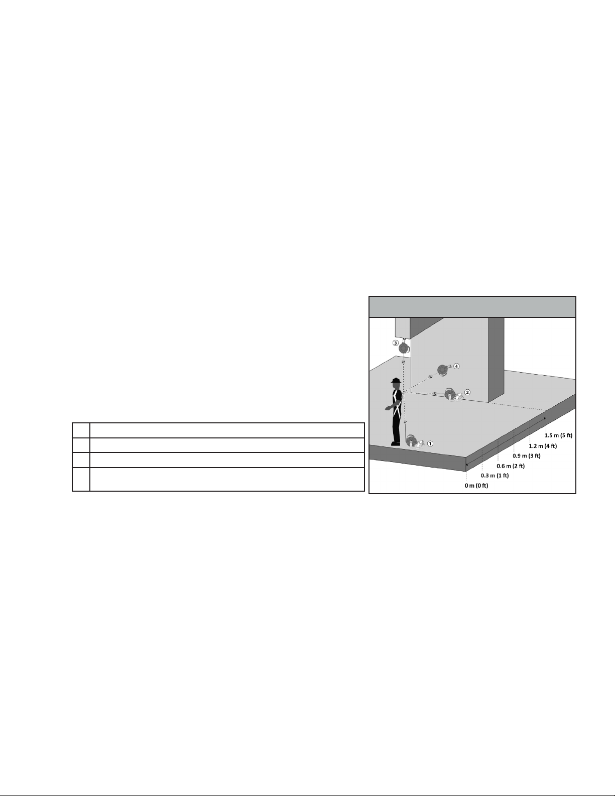
Figure 2 - Anchorage Locaons
3.0 Applicaon
3.1 Purpose: The FallTech Contractor Leading Edge SRL-LE is designed to be used as a component in a Personal Fall Arrest System (PFAS),
to provide a combinaon of worker mobility and fall protecon as required for inspecon work, general construcon, maintenance work,
oil producon, conned space work, etc. The SRL-LE is intended for fall protecon in Leading Edge applicaons where falls may occur over
edges.
3.2 Personal Fall Arrest System: A PFAS is an assembly of components and
subsystems used to arrest a person during a fall event. A PFAS typically
consists of an anchorage, a deceleraon device such as an Energy Absorbing
Lanyard (EAL), a Self-Retracng Device (SRD), or a Fall Arrestor Connecng
Subsystem (FACSS), and a properly ed Full Body Harness (FBH). Maximum
permissible free fall in a typical PFAS is 1.8 m (6 ). The SRD discussed in this
manual may be used in non-overhead anchorage situaons. Clearance
calculators provided in this manual oer methods for calculang MRFC for
non-overhead anchorage locaons when the SRD is set back from 0 m (0 )
to 1.2 m (4 ) and non-overhead anchorage locaons that are set back 1.5 m
(5 ) or greater, see Figure 2.
1Anchorage of SRD at Foot Level with 0 m (0 ) Setback from Leading Edge
2Anchorage of SRD at Foot Level with 1.5 m (5 ) Setback from Leading Edge
3Overhead Anchorage of SRD Above Dorsal D-Ring
4Anchorage of SRD Above Dorsal D-Ring with 1.5m (5 ) Setback from Leading
Edge
2.1 Canadian Standards Organizaon (CSA): The Contractor SRL-LE described in this manual, when used per the instrucon in this manual
meets or exceeds CSA Z259.2.2-2017. CSA requires that all SRDs be classied according to their respecve type, and are classied either
as; Class SRL, Class SRL-R, Class SRL-LE, or Class SRL-LE-R. The Contractor SRL-LE Self Retracng Device in this manual is Class SRL-LE.
CSA Test Parameters used in this manual are:
The Arrest Distance is the total vercal distance required to arrest a fall. The Arrest Distance includes the deceleraon distance and the
acvaon distance. The Average Arrest Force is the average of the forces applied to the body and the anchorage by the fall protecon
system. The Maximum Peak Arrest Force is the maximum amount of force that may be applied to the body and the anchorage by the fall
protecon system. In addion to the above tests conducted in ambient condions, the units must be retested for average and peak forces
under certain environmental condions, where the units are cooled, then tested, and saturated in water and tested again. Separate units
are used for each test. All test results are recorded.
This test data is then used to establish the basis for fall clearance guidelines published in the user instrucon manual.
• Arrest Distance (AD)
• Average Arrest Force (AAF)
• Maximum Peak Arrest Force (MPAF)
3.3 Horizontal Lifeline (HLL) and Rail Systems: The SRD may be aached to rigid and exible anchors provided that all HLL or rail system
applicaons, installaon, and uses are under the supervision of a qualied person.
3.4 Rescue: Ensure a wrien rescue plan, method and system is in place and readily available for rapid response. Rescues may require
specialized equipment or measures. Rescue operaons are beyond the scope of this manual. ‘
3.5 Applicaon Limits: The SRD discussed in this manual is designed for Leading Edge applicaons. However, take cauon to avoid very
sharp edges such as sheared metals, metals cut with an abrasive disk, or ame-cut metals. Also take cauon around very abrasive surfaces
and edges, such as concrete or stone, as these edges and surfaces may abrade the lifeline or the energy absorber during a fall event.
4.0 System Requirements
4.1 Capacity: The SRD is designed for use by a single user with a combined weight of user, tools, clothing, etc., of 59 kg (130 lbs) to no
more than 140 kg (310 lbs).
4.2 Compability of Connectors: Connectors are considered to be compable with connecng elements when they have been designed
to work together in such a way that their sizes and shapes do not cause their gate mechanisms to inadvertently open regardless of how
they become oriented. Contact FallTech if you have any quesons about compability. Connectors must be compable with the
anchorage or other system components. Do not use equipment that is not compable. Non-compable connectors may unintenonally
disengage. Connectors must be compable in size, shape, and strength. Self-closing, self-locking connectors are required by CSA.
022420CMSRD08 Rev A 5