CoachComm X SYSTEM User manual

OPERATING MANUALOPERATING MANUAL

This page is intentionally blank.

OPERATING MANUAL
800.749.2761 www.coachcomm.com
iii
Thank you from CoachComm!
We at CoachComm want to thank you for purchasing an X-System Sideline Communications System. We have made every
effort to build a reliable, intuitive communication system that provides the functionality that you can count on come game
day.
One of our goals in the design of X-System was to build on the advances set forth by the previous Tempest®NG System and
to provide users with unmatched RF performance. You will be able to begin using your new X-System with nothing more
than the Game Day Guide. However, to fully benet from the available features, please read this manual carefully.
We want X-System to make your job easier and your game day experience positive. To successfully familiarize yourself with
the many diverse and powerful features X-System offers, it is crucial that you acquaint yourself with the manual.
We are committed to providing you with a high quality product that will deliver years of trouble free service. Should you
experience any problem with your X-System equipment, whether it is under warranty or not, we will do our best to take
care of your needs.
Thank you for choosing CoachComm for your sideline communication needs.
CoachComm LLC
205 Technology Parkway
Auburn, AL 36830
Phone: 334-321-2300
Fax: 888-329-2658
www.coachcomm.com
© 2016–2020 CoachComm LLC. All rights reserved.
Document Reference: 2020.06 D0000281_G
© Telex is a registered trademark of Telex Communications, Inc.
© Audiocom is a registered trademark of Bosch Security Systems, Inc.

OPERATING MANUAL
800.749.2761 www.coachcomm.com
iv
Table of Contents
Safety Information ................................................................................................................................................1
Electrical Safety..............................................................................................................................................1
Battery Safety.................................................................................................................................................1
Transit Safety .................................................................................................................................................3
Protecting Yourself and Those Around You.......................................................................................................5
Introduction ..........................................................................................................................................................6
What makes X-System so different?...............................................................................................................6
Frequency Considerations...............................................................................................................................6
Stadium Wiring Considerations .......................................................................................................................7
Block Diagrams ....................................................................................................................................................8
Sideline to Wired Press Box Unit (System Diagram).........................................................................................8
Wired Press Box Unit Block Diagram ..............................................................................................................9
Sideline Cart Block Diagram .........................................................................................................................10
Game Day Setup.................................................................................................................................................11
X-System Components ......................................................................................................................................16
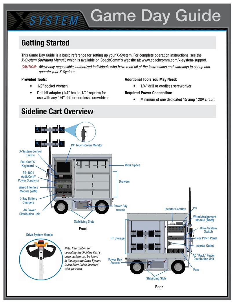
Sideline Cart Overview..................................................................................................................................16
Drive System Overview.................................................................................................................................19
Wired Press Box Unit Overview .....................................................................................................................22
PS-4001 Power Supply(s).............................................................................................................................22
Wired Interface Module (WIM).......................................................................................................................23
Ringdown Circuits ........................................................................................................................................25
Wired Assignment Module (WAM) .................................................................................................................26
Sideline Cart Power Management.................................................................................................................27
Sideline Cart Rear Patch Panel......................................................................................................................30
Control Unit (XCU-44)....................................................................................................................................31
Radio Transceivers (XRT-900 and XRT-2400) ...............................................................................................35
Radio Packs (XRP-13) ..................................................................................................................................37
System Accessories............................................................................................................................................44
Wired BeltPacks ..........................................................................................................................................44
Field and Press Box Cables...........................................................................................................................44
Headsets ......................................................................................................................................................45
System Conguration File ...................................................................................................................................46
Saving a System Conguration File...............................................................................................................46
Uploading a Conguration File ......................................................................................................................46
X-Ware ...............................................................................................................................................................49
Home Screen................................................................................................................................................49
RP Icon.........................................................................................................................................................50
Prole Screen...............................................................................................................................................51
Additional System Views...............................................................................................................................53
X-Ware Advanced Settings............................................................................................................................56
System Setup and Operation...............................................................................................................................64
RT Mast Assembly ........................................................................................................................................64
Setting Home/Away Status ...........................................................................................................................67
Turning On 2-Wire Ports and Adjusting Levels...............................................................................................67
Assigning Conferences to Dry Pair Connections (Wired Port) .........................................................................68
Assign Proles from the Control Unit.............................................................................................................68
Auto Null Process ........................................................................................................................................69

OPERATING MANUAL
800.749.2761 www.coachcomm.com
v
Wireless Component Setup and Integration...................................................................................................70
Understanding Link Quality ..........................................................................................................................70
System Maintenance ..........................................................................................................................................71
Basic Maintenance .......................................................................................................................................71
Off-Season Storage: Inverter Battery Information ..........................................................................................71
Lithium-Polymer Battery Maintenance ..........................................................................................................72
Installing and Updating X-Ware.....................................................................................................................73
Updating Device Firmware............................................................................................................................76
Troubleshooting Common Issues.........................................................................................................................80
Product Support..................................................................................................................................................81
Returning Equipment for Repair or Maintenance ..........................................................................................81
License Information ............................................................................................................................................82
Radio Device License Information.................................................................................................................82
Non-Radio-Device License Information.........................................................................................................83
X-Ware™End User License Agreement (EULA) ..............................................................................................84
Warranty Information ..........................................................................................................................................87
Limited Warranty ..........................................................................................................................................87
Parts Limited Warranty .................................................................................................................................87
Glossary .............................................................................................................................................................88
Specications .....................................................................................................................................................89
Sideline Cart Specications ..........................................................................................................................89
Control Unit Specications ...........................................................................................................................90
Radio Transceiver Specications ..................................................................................................................91
Radio Pack Specications.............................................................................................................................92
Appendix A: Wireless Press Box Unit (WPB1) .......................................................................................................93
Sideline to Wireless Press Box Unit (WPB1) (System Diagram) ......................................................................93
Wireless Press Box Unit (WPB1) Block Diagram ............................................................................................94
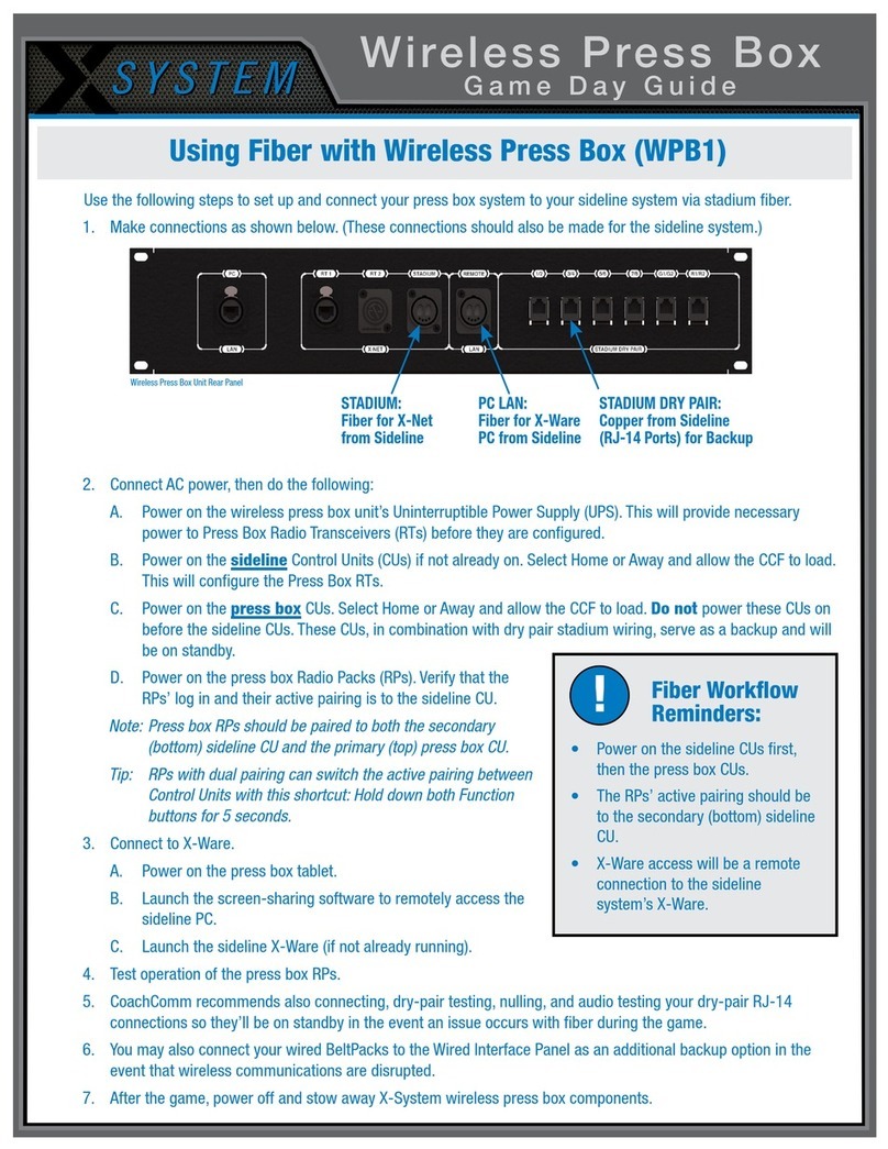
Wireless Press Box Unit (WPB1) Overview.....................................................................................................95
Wireless Press Box (WPB1) Rear Patch Panel................................................................................................96
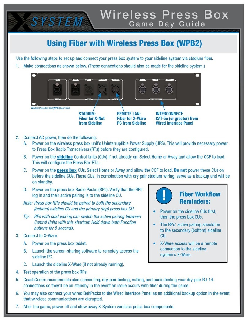
Using Fiber with Wireless Press Box (WPB1) ................................................................................................97
Using Dry Pair with Wireless Press Box (WPB1).............................................................................................98
Appendix B: Wireless Press Box Unit (WPB2) .......................................................................................................99
Sideline to Wireless Press Box Unit (WPB2) (System Diagram) ......................................................................99
Wireless Press Box Unit (WPB2) Block Diagram ..........................................................................................100
Wireless Press Box Unit (WPB2) Overview...................................................................................................101
Wireless Press Box (WPB2) Rear Patch Panel..............................................................................................103
Wired Interface Panel (WIP).........................................................................................................................104
Using Fiber with Wireless Press Box (WPB2) ..............................................................................................106
Using Dry Pair with Wireless Press Box (WPB2)...........................................................................................107

OPERATING MANUAL
800.749.2761 www.coachcomm.com
vi
This page is intentionally blank.

OPERATING MANUAL
800.749.2761 www.coachcomm.com
1
Safety Information
The following pages detail important safety information related to the ownership and operation of CoachComm’s X-System.
Please ensure all personnel review the warnings and safety recommendations included in this document before operating,
transporting, or towing the sideline cart in order to prevent equipment damage and/or serious personal injury.
Throughout this document you will see the following indicators for important safety information and alerts:
WARNING: Ignoring these warnings may cause permanent or serious injury or death as a result of
incorrect operation.
CAUTION: Ignoring these cautions may cause moderate injury or property damage as a result of
incorrect operation.
Electrical Safety
WARNING: ELECTRIC SHOCK RISK
»Do not submerge any part of X-System in water.
»Refer all servicing to qualied service personnel. Do not attempt to modify, disassemble, or open any
X-System components. Exposing the electrical system may result in equipment damage and serious
personal injury, including electric shock. Equipment damage caused by unqualied personnel may void the
product warranty associated with your X-System.
CAUTION:SYSTEM DAMAGE RISK
»Protect the power cords from foot trafc. Do not allow cords to be crimped or pinched, particularly at plugs,
electrical outlets, and the point they exit from the apparatus. Routinely inspect power cords for any signs of
fray or extensive wear. Immediately replace any damaged cords.
»Keep all ventilation openings clean and unobstructed. Failure to do so could cause the system to overheat,
which could cause personal injury or property damage.
»Unplug X-System during lightning storms to prevent power surges that could damage electrical
components or cause re.
At a minimum, the X-System sideline cart requires one dedicated 15 amp 120V circuit. You should test and verify that any
circuits are working properly on a routine basis.
Battery Safety
Sideline Cart Inverter Battery Safety
WARNING: EXPLOSIVE GASES RISK
»Keep sparks, ames, and metal objects away from batteries, sideline cart, and area of operation. The gas
exhaust from the batteries causes re and explosions. This may cause SERIOUS INJURY or DEATH.
»Ventilate the area when charging batteries or operating the sideline cart in an enclosed space.
»CoachComm recommends keeping a Class-D re extinguisher available when charging inverter batteries.
Though the batteries are sealed, the gases inside are highly ammable.

OPERATING MANUAL
800.749.2761 www.coachcomm.com
2
WARNING: CORROSIVE MATERIAL RISK
»Wear a full face shield, chemical-resistant gloves, and protective clothing/shoes when working on or near
batteries.
»Battery acid is a harmful, corrosive material and may cause permanent injury if it comes into contact
with skin or eyes. If contact with skin or eyes occurs, immediately ush with water and seek medical
assistance.
WARNING: ELECTRIC SHOCK RISK
»The electricity stored in batteries can cause electric shock resulting in serious bodily injury or death, even
at low voltages.
»When servicing or inspecting electrical components, unplug from AC power and turn the battery bank
breaker off to avoid electrical shock or damage to the electrical system.
»Use insulated tools when working near batteries or electrical connections to avoid electrical shock or
damage to the electrical system.
CAUTION:
SYSTEM DAMAGE RISK
»Perform a periodical visual inspection to check that all connections and battery cables are securely
attached to the terminal and tight; improper connections can result in system malfunction, battery post
breakages, meltdown, or re.
»Do not lay any objects on batteries or terminals to avoid short circuiting of components or wiring.
»Do not wear metal jewelry such as rings, watches, chains, etc., when servicing the sideline cart batteries to
avoid short circuiting of components or wiring.
»Additional maintenance and off-season storage instructions related to the Inverter battery are provided on
page 50 of the X-System Operating Manual.
Radio Pack (RP) Battery Safety
WARNING:
EXPLOSION AND FIRE RISK
»Battery explosion is possible if incorrect type is used. Use only batteries approved for use with X-System
Radio Packs. If powering the Radio Pack with AA batteries, use only alkaline or carbon-zinc batteries.
»Do not leave the battery unattended while charging. Immediately unplug unit if battery begins to swell
or emit smoke while charging. If battery bursts or chemicals begin to leak out of battery housing, the
chemicals will react with the air and cause a re.
»CoachComm recommends keeping a Class-D re extinguisher available when charging lithium-polymer
batteries. The chemicals inside lithium-polymer batteries are highly ammable.
»Do not allow batteries to overheat (reach temperatures of above 140 degrees Fahrenheit).
»Batteries that appear swollen, deformed, or damaged, or that do not t properly should never be used.
Properly dispose of any batteries in this condition in accordance with the instructions provided by your local
authorities. For more information and local drop-off sites, visit http://www.call2recycle.org/.

OPERATING MANUAL
800.749.2761 www.coachcomm.com
3
Transit Safety
WARNING:
SEVERE INJURY AND SYSTEM DAMAGE RISK
»Never allow individuals to stand, sit, climb, or ride on any part of sideline cart to prevent injury.
»Never drive or tow sideline cart near drop-offs, ditches, or embankments; reduced traction could result in
slippage, tipping, or other loss of control of your tow vehicle and/or sideline cart.
»Never drive or tow sideline cart on the road shoulder or near slopes greater than 15%. Reduced traction
could result in slippage, tipping, or other loss of control of your tow vehicle and/or sideline cart.
»Never operate on wet or slippery slopes. Reduced traction could result in slippage, tipping, or other loss of
control of your tow vehicle and/or sideline cart.
»Do not turn on a slope. Reduced traction could result in slippage, tipping, or other loss of control of your
tow vehicle and/or sideline cart.
»Secure all system components, doors, and drawers before transit to prevent damage to those parts during
transit.
»CoachComm recommends having assistance from multiple people when the sideline cart is in transit.
Additional people can provide visibility and terrain cues to the tow vehicle or drive system operator.
Drive System Safety
CAUTION:
SYSTEM DAMAGE AND INJURY RISK
»Ensure a tight grip on sideline cart drive system handle when in operation.
»The emergency stop/reverse button on the drive system handle provides an immediate halt and brief
reversal in the event of a collision or operator fall.
Utilize the drive system’s horn button to signal the sideline cart’s movements for nearby vehicles and people.
If the drive system is inoperable, it can be disengaged
and overridden with the mechanical slider behind the
back left wheel (accessible from the side of the cart
opposite the drive system handle.)
Towing Safety
You should only tow the sideline cart behind a vehicle
when the drive system is inoperable.
CoachComm recommends the following types of tow
vehicles for the sideline cart: All Terrain Vehicle, golf
cart or other electric towing vehicle, utility vehicle, or
compact or sub-compact tractor.
If your tow vehicle will not travel by itself over the
terrain by which you plan to tow the sideline cart,
then it is not a suitable terrain for the sideline cart to
traverse. In addition, most tow vehicles are capable
of going over terrain that the sideline cart is not.
Be cautious and nd a different route to prevent
equipment damage and a potential voiding of the
X-System warranty.
Figure 1: Drive System Handle Label

OPERATING MANUAL
800.749.2761 www.coachcomm.com
4
When towing your sideline cart behind a vehicle, follow the safety instructions below:
CAUTION:
SYSTEM DAMAGE AND INJURY RISK
»Have a complete working knowledge of your tow vehicle and know how to handle it with the sideline cart
attached.
»Make sure the sideline cart’s brake is disengaged via the mechanical slider prior to towing. Failure to do so
will result in drive system damage.
»Turn off the battery bank breaker and ensure the system is disconnected from AC power prior to towing.
»Make sure towing hitch connections are properly secured prior to towing. Only use the manufactured
sideline cart hitch to connect to the tow vehicle; do not connect a vehicle to the cart’s drive system or axle.
Failure to do so may result in sideline cart damage or injury.
»Drive at a maximum speed of 3 mph. Higher speeds may cause a tip hazard or damage to the electric drive
system.
»Avoid sharp turns to prevent damaging the front steering system.
»Decrease speed at all corners, and watch the swing of both the rear of the tow vehicle and the sideline
cart.
Parking Safety
The sideline cart drive system uses a magnetic brake, which engages as a wheel brake and parking brake when the drive
system is powered off.
CAUTION:
SYSTEM DAMAGE AND INJURY RISK
»Never park the sideline cart on a steep grade or slope. Reduced traction could result in slippage, tipping, or
other loss of control of the sideline cart.
»Install and adjust the sideline cart stabilizers on all four corners of the sideline cart to prevent tipping when
parked and in use.
»Do not use blocks to increase height of system.
Transportation Safety
When transporting your sideline cart in a truck, follow the safety instructions below to prevent damage to your system or
nearby equipment.
CAUTION:
SYSTEM DAMAGE RISK
»Secure the cart in your truck using the tie-down points indicated in Figure 18 and Figure 19 on page 18 of
this manual.
»CoachComm recommends tying down with four (4) cargo straps rated for at least 5000 lbs.
»Always ensure that the sideline cart’s brake is engaged. (The brake lever should be in Position A as indicated
on page 19 of this manual.)
»Protect the corners and edges of your cart by padding them with cardboard.
»Stop often to check your load.
»Inspect cargo straps often and replace them if any damage is noted.

OPERATING MANUAL
800.749.2761 www.coachcomm.com
5
Protecting Yourself and Those Around You
Allow only responsible individuals who are familiar with these general safety rules and operating instructions to use your
X-System. Never allow people unfamiliar with these rules and instructions to set up or operate your system.
WARNING:
SEVERE INJURY AND SYSTEM
DAMAGE RISK
»The Radio Transceiver mast is top-heavy and
can be a crush hazard. Ensure a tight grip when
engaging or releasing safety pins to prevent
serious personal injury or system damage.
CAUTION:
SYSTEM DAMAGE AND INJURY RISK
»The drive system handle and sideline cart
doors, drawers, and compartments can be
pinch hazards. Utilize all installed safety pins on
movable components.
»Never, under any conditions, remove, bend, cut,
t, weld, or otherwise alter standard parts of the
X-System. Modications to your system could
cause personal injuries and property damage
and will void your warranty.
»Only use attachments/accessories/cables/
hardware provided by the manufacturer.
»Do not remove or cover any safety labels on the sideline cart. If a label is damaged or removed, contact a
CoachComm support technician for a replacement.
Figure 2: Crush Hazard Label

OPERATING MANUAL
800.749.2761 www.coachcomm.com
6
Introduction
What makes X-System so different?
CoachComm has been building and providing wired and wireless systems for over 25 years to supply quality
communications to D-1 teams nationwide. Therefore, CoachComm’s knowledge of wireless technology in the D-1 football
arena is vast, and our experience is deep. When it came time to build the next generation of equipment to service that
industry—CoachComm was up to the challenge.
X-System makes use of the newest available communications technology and meets our customers’ demands for more
users, better audio, and future-based features.
X-System is the rst wireless intercom system to innovate the following unique features:
• Better Frequency-Hopping Spread Spectrum performance in domes
• Enhanced 900MHz and 2.4GHz band wireless performance
• X-Ware touchscreen user interface for greater visibility and control of the system
• State-of-the-art rugged and stable Sideline Cart design
• Better 7k audio quality
These features come together to form a powerful product called X-System. X-System, together with enhanced tools for the
wired portion of the system, makes for an incredibly robust, easy to operate system.
Frequency Considerations
900MHz and 2.4GHz
CoachComm designed the new X-System to operate seamlessly in both the 900MHz and the 2.4GHz frequency bands. This
allows multiple devices to operate within the bands with minimal interference or reduction of range and performance.
The 2.4GHz ISM frequency band is a globally accepted portion of the RF spectrum that is available for unlicensed use
virtually anywhere worldwide with no frequency coordination. In the United States, the 2.4GHz band is 2400–2483.5 MHz.
X-System utilizes up to 83 MHz of this spectrum from 2400–2483 MHz.
The 900MHz ISM frequency band is a portion of the RF spectrum available for unlicensed use in North America and other
various locations with no frequency coordination. In North America the 900MHz band is 902–928 MHz. X-System utilizes up
to 26 MHz of this spectrum.
Frequency-Hopping Spread Spectrum
Frequency-Hopping Spread Spectrum (FHSS) is a means of RF transmission. In FHSS, the signal hops to various
frequencies—hence the name. In doing so, it spreads the data (voice in our case) across a wide area of the RF spectrum.
Devices such as those in X-System collide constantly with other devices in that frequency spectrum and must have
mechanisms built into their protocol to allow for data redundancy to provide acceptable user performance.

OPERATING MANUAL
800.749.2761 www.coachcomm.com
7
Stadium Wiring Considerations
Twisted Copper with RJ-14 Connector
We recommend an uninterrupted run of Cat 3 UTP cable from sideline to press box (for both home and visitor). By denition,
each RJ-14 connector has two pairs (i.e., four wires). It is often confused with an RJ-11 (two wires). Some phone technicians
will call these RJ-11 4-wire jacks.
Specications:
Max Distance ≤ 3000 ft. (914.4 m)
Connector Type RJ-14
Wire Type Cat 3 UTP (unshielded twisted pair) copper phone line (At least 12 pairs required, though we
recommend 24 pairs in order to have a full backup set.) Each RJ-14 connection consists of 2
pairs wired.
Wire Size 22 to 24 AWG
Please note the unique wiring of the RJ-14 for the “NG” application in Figure 3.
Fiber-Optic Cable
Requirements for use with X-System Wireless Press Box Unit
For stadium wiring, CoachComm recommends an uninterrupted run of at least eight strands of
single-mode optical ber (SMF) cable from sideline to press box (for both home and visitor). We
require at least four strands for X-System operation, so strands beyond those would be spares.
The X-System™Sideline Cart, ATA package, and Wireless Press Box systems contain Neutrik
OpticalCon Duo panel connectors and cables. (Neutrik OpticalCon Duo Connectors are
ruggedized pass-through connectors compatible with standard LC duplex terminated ber
cable.) For ease-of-use, CoachComm recommends using Neutrik OpticalCon Duo Chassis
Connectors for eld and press box stadium termination.
Specications:
Max Distance ≤ 10 km (6.2 miles)
Fiber Type 9/125 µm Single-Mode Fiber (SMF) strands (At least 4 strands
required, though we recommend 8 strands in order to have a full
backup set.) Each LC duplex connection consists of 1 pair (i.e., 2
strands).
Connector Type LC duplex pair into Neutrik OpticalCon Duo (Part # NO2-4FDW-A)
Stadium Termination At least 2 separate Neutrik OpticalCon Duo Chassis Connectors in
each location—press box and sideline.
Line 1
Line 2
Figure 3: RJ-14 Wiring
CoachComm System
(RJ-14 Connections)
Stadium Wiring
(RJ-14 Connections)
Lines 1/2 Pairs 1 and 2
Lines 3/4 Pairs 3 and 4
Lines 5/6 Pairs 5 and 6
Lines 7/8 Pairs 7 and 8
Ground 1/Ground 2 Pairs 9 and 10
Ringdown 1/Ringdown 2 Pairs 11 and 12
Figure 4: Figure 2: Single-Mode Fiber (2 Strands)
and Duplex LC Termination
Figure 5: Figure 3: Neutrik opticalCON DUO
Cable Connector
Figure 6: Figure 4: Neutrik opticalCON DUO
Chassis Connector

OPERATING MANUAL
800.749.2761 www.coachcomm.com
8
Block Diagrams
The following pages contain block diagrams that represent the principal parts of X-System and their relationships.
Sideline to Wired Press Box Unit (System Diagram)
See page 22 for more information about the Wired Press Box Unit. See page 30 for more information about the
Sideline Cart Patch Panel.
Figure 7: X-System Block Diagram
PressBox Panel
PressBox Unit Front
Sideline Panel
RJ-14 Patch Cables
RJ-14 Patch Cables
Sideline Cart Patch Panel
X-System Sideline Cart
PressBox Panel
Stadium
Wiring

OPERATING MANUAL
800.749.2761 www.coachcomm.com
9
Wired Press Box Unit Block Diagram
Figure 8: Wired Press Box Unit Block Diagram

OPERATING MANUAL
800.749.2761 www.coachcomm.com
10
Sideline Cart Block Diagram
Figure 9: Sideline Cart Block Diagram

OPERATING MANUAL
800.749.2761 www.coachcomm.com
11
Game Day Setup
The procedures in this section serve as a reference for a typical game day setup. You can nd more in-depth information
about the devices and processes mentioned here in later sections of this Operating Manual.
Note: If you are setting up a Wireless Press Box Unit, additional Game Day Setup instructions are provided in
this document’s Appendix starting on page 93.
Getting Started
This Game Day Guide is a basic reference for setting up your X-System. For complete operation instructions, see the rest of
this manual.
CAUTION: Allow only responsible, authorized individuals who have read all of the instructions and warnings to set up
and operate your X-System.
Provided Tools:
• 1/2” socket wrench
• Drill bit adapter (1/4” hex to 1/2” square) for use with any 1/4” drill or cordless
screwdriver
Additional Tools You May Need:
• 1/4” drill or cordless screwdriver
Required Power Connection:
• Minimum of one dedicated 15 amp 120V circuit
1. Position and stabilize cart.
1a. Once the Cart is positioned at mideld, insert each of the four stabilizers into
their associated slots.
1b. Extend the stabilizers to the ground using either the socket wrench or the drill bit
adapter and drill. Continue extending until stabilizers have made sufcient ground contact to stabilize the cart.
Note: The cart stabilizers are not intended to lift the cart.
2. Prepare RT Mast
Note: The following steps are referenced in Figure 11 and should be performed with at least two people.
2a. Remove the mast from its storage area and insert it into the locked and upright mast receiving tube.
2b. Align the mast so your RT mounting bracket(s) (when attached) will be parallel to the sideline and secure the
mast with pin 1 at the bottom of the tube.
2c. Secure the mast and tube with one hand, then remove pins 2 and 3 from the top of the tube. Carefully lower
the mast to a bench or chair level with the cart. (See Figure 90 on page 65 for a detailed drawing of these pin
locations.)
CAUTION:
Ensure there is a minimum of 20 feet of clearance beside the Cart before lowering the mast.
2d. Extend the mast to the desired height, locking each section in place as you go. (A minimum of 12 feet is
recommended.)
2e. If you are not fully extending the mast, align the index holes of the non-extended sections and secure by inserting
pin 4. This prevents the mast from rotating while extended. (See Figure 90 on page 65 for drawing of pin
locations.)
Figure 10: Sideline Cart Stabilizer

OPERATING MANUAL
800.749.2761 www.coachcomm.com
12
3. Mount RTs and secure mast.
Note: The following steps are referenced in Figure 11 and should be performed with at least two people.
3a. Mount the RT mounting bracket(s) to the top of the mast using the provided pins.
3b. Connect the red RT cable to the rst RT on the top bracket.
Note: If using a second RT bracket, also connect the blue RT cable to the rst RT on that bracket.
3c. Attach the cable’s strain relief to the eye bolt on the mounting bracket.
3d. Bend the antennas so they are parallel to the ground (90° angle between the antenna and the RT) and point their
tips toward the opposing team’s RT mast.
3e. Carefully walk the mast up until the receiving tube is upright and ush with the Cart, then secure it with pins 2
and 3 (previously removed in 2c). (See Figure 90 on page 65 for a detailed drawing of these pin locations.)
(2d.) Extend mast.
(3c.) Attach cable’s
strain relief.
(3e.) Raise
and secure.
Allow at least 20 feet for clearance.
(3a.) Mount the RT
bracket(s).
(3b.) Connect RT cable.
(2c.) Secure tube while
removing Pins 2 & 3.
Lower to ground.
(2b.) Align mast
and secure with
Pin 1 at bottom of
tube.
(2a.) Insert
mast.
Pins 2 & 3
Pin 1
90o
Align mast so RT bracket(s)
will be parallel to eld.
Pin 4
Figure 11: Sideline Cart RT Mast Setup

OPERATING MANUAL
800.749.2761 www.coachcomm.com
13
4. Connect RT cable and dry pair to cart.
Note: The following steps are referenced in Figure 12 below.
4a. Connect the red RT cable to the “TOP RT SET” port on the Cart’s rear rack patch panel.
Note: If using a second RT bracket, connect the blue RT cable to the “BOTTOM RT SET” port.
4b. Connect stadium’s dry pair panel to the corresponding “STADIUM DRY PAIR” ports on the rear patch panel.
5. Connect AC power and power on the cart.
5a. Route an external power extension cord through the Cart’s hatch and connect it to the main AC power cord in
the rear of the Cart. At a minimum, the cart requires one dedicated 15 amp 120V circuit.
WARNING: DANGER! Users should exercise extreme care when working with electricity. Additional care
should be used when working with electricity outdoors in inclement weather. When working
outdoors or near water, always connect the system into a ground-fault interrupting circuit.
CAUTION:
Secure and protect any cords to prevent walkway hazards and potential contact with moisture.
5b. Power on the Cart via Master On/Off switch on the Cart’s rear panel. (See Figure 13.)
5c. Conrm that all devices on the front rack are powered on, including the AC power distribution unit, Control Unit(s),
and monitor.
Figure 12: Patch Panel RT Cable and Dry Pair Ports
(4a.) Connect RT
cable to rear Cart
panel.
(4b.) Connect dry pairs
to rear Cart panel.
(5b.) Power on the Cart.
Figure 13: Patch Panel Master On/Off Switch

OPERATING MANUAL
800.749.2761 www.coachcomm.com
14
6. Set Home/Away status.
6a. Follow the prompt on your top (master) CU to set your system’s Home/Away status.
Important: No RF transmission will occur until the Home/Away status is selected. Failure to set this status
properly may result in RF interference.
The Home/Away setting aids customers with hopping pattern
coordination between RTs and Radio Packs. Based on this
setting, all of the RTs on the system will be assigned specic
hopping patterns by the Control Unit (CU). It is very important
to set this status correctly. Hopping pattern coordination
prevents interference between X-Systems.
During startup, the conguration le (CCF) will begin loading
while the Home/Away prompt is displayed on the top CU. A
progress bar shows the load process on the bottom CU. Once
the Home/Away prompt is cleared, the CCF load progress can
be seen on both CUs.
6b. Wait until the CUs display the “CCF Loaded” message along with a conguration le summary. (The bottom CU will
take about 30 seconds longer than the top.) When the CCF load is complete, the home screen will display on the
front of the CU(s) and you can proceed.
6c. Open X-Ware and allow its Home screen to load.
7. Set up press box unit and null system.
Note: The procedures in this step should be performed by at least two people.
7a. Once the Sideline Cart is congured, set up and connect power to the Press Box Unit. Have someone stay with
the Sideline Cart to assist in the verication of dry pairs during this step.
7b. Connect dry pair panel in the Press Box to the corresponding ports on the rear of the WIM in the Press Box
Unit.
7c. Connect wired BeltPacks and cables for each coach. Make sure all TALK buttons are off.
7d. Auto-null all of the lines from the sideline using X-Ware’s Conference view (under the System Settings menu). If
there is noticeable echo on some channels of the wireless components, conrm that all TALK buttons are off and
repeat the auto-null step.
Figure 14: CU Home/Away Prompt at Startup
Other manuals for X SYSTEM
1
This manual suits for next models
6
Table of contents
Other CoachComm Conference System manuals

CoachComm
CoachComm Tempest User manual

CoachComm
CoachComm tempest fx User manual

CoachComm
CoachComm X System WPB1 User manual

CoachComm
CoachComm X SYSTEM Service manual

CoachComm
CoachComm X-System User manual

CoachComm
CoachComm Tempo Go User manual

CoachComm
CoachComm Tempest NG User manual

CoachComm
CoachComm eVenue Tempo User manual

CoachComm
CoachComm X-System User manual

CoachComm
CoachComm X2 User manual