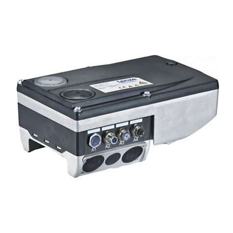
Lenze 8400 motec Series Use and care manual

L
EDS84DMOTCAN
13395082
Ä.HSsä
Communication Manual
E84DGFCCxxx
CANopen communication unit
8400 motec
L-force Communication

2LEDS84DMOTCAN EN 3.0 - 11/2011

EDS84DMOTCAN EN 3.0 - 11/2011 L3
Communication manual 8400 motec CANopen
Contents
Contents
1About this documentation . . . . . . . . . . . . . . . . . . . . . . . . . . . . . . . . . . . . . . . . . . . . . . . . . . . . . . . . . 6
1.1 Document history . . . . . . . . . . . . . . . . . . . . . . . . . . . . . . . . . . . . . . . . . . . . . . . . . . . . . . . . . . . . . . . 8
1.2 Conventions used . . . . . . . . . . . . . . . . . . . . . . . . . . . . . . . . . . . . . . . . . . . . . . . . . . . . . . . . . . . . . . . 9
1.3 Terminology used . . . . . . . . . . . . . . . . . . . . . . . . . . . . . . . . . . . . . . . . . . . . . . . . . . . . . . . . . . . . . . . 10
1.4 Notes used. . . . . . . . . . . . . . . . . . . . . . . . . . . . . . . . . . . . . . . . . . . . . . . . . . . . . . . . . . . . . . . . . . . . . . 11
2Safety instructions . . . . . . . . . . . . . . . . . . . . . . . . . . . . . . . . . . . . . . . . . . . . . . . . . . . . . . . . . . . . . . . .12
2.1 General safety and application instructions. . . . . . . . . . . . . . . . . . . . . . . . . . . . . . . . . . . . . . . 12
2.2 Device and application-specific safety instructions . . . . . . . . . . . . . . . . . . . . . . . . . . . . . . . . 13
2.3 Residual hazards . . . . . . . . . . . . . . . . . . . . . . . . . . . . . . . . . . . . . . . . . . . . . . . . . . . . . . . . . . . . . . . . 13
3Product description . . . . . . . . . . . . . . . . . . . . . . . . . . . . . . . . . . . . . . . . . . . . . . . . . . . . . . . . . . . . . . . 14
3.1 Application as directed . . . . . . . . . . . . . . . . . . . . . . . . . . . . . . . . . . . . . . . . . . . . . . . . . . . . . . . . . . 14
3.2 Product features and variants. . . . . . . . . . . . . . . . . . . . . . . . . . . . . . . . . . . . . . . . . . . . . . . . . . . . 15
3.3 Connections and interfaces . . . . . . . . . . . . . . . . . . . . . . . . . . . . . . . . . . . . . . . . . . . . . . . . . . . . . . 17
4Technical data . . . . . . . . . . . . . . . . . . . . . . . . . . . . . . . . . . . . . . . . . . . . . . . . . . . . . . . . . . . . . . . . . . . . 19
4.1 General data and operating conditions of the CANopen . . . . . . . . . . . . . . . . . . . . . . . . . . . 19
4.2 Supported protocols. . . . . . . . . . . . . . . . . . . . . . . . . . . . . . . . . . . . . . . . . . . . . . . . . . . . . . . . . . . . . 20
4.3 Communication time. . . . . . . . . . . . . . . . . . . . . . . . . . . . . . . . . . . . . . . . . . . . . . . . . . . . . . . . . . . . 21
5Installation . . . . . . . . . . . . . . . . . . . . . . . . . . . . . . . . . . . . . . . . . . . . . . . . . . . . . . . . . . . . . . . . . . . . . . . 22
5.1 Mechanical installation. . . . . . . . . . . . . . . . . . . . . . . . . . . . . . . . . . . . . . . . . . . . . . . . . . . . . . . . . . 23
5.2 Electrical installation . . . . . . . . . . . . . . . . . . . . . . . . . . . . . . . . . . . . . . . . . . . . . . . . . . . . . . . . . . . . 24
5.2.1 Network topology . . . . . . . . . . . . . . . . . . . . . . . . . . . . . . . . . . . . . . . . . . . . . . . . . . . . . . . 24
5.2.2 Bus termination . . . . . . . . . . . . . . . . . . . . . . . . . . . . . . . . . . . . . . . . . . . . . . . . . . . . . . . . . 25
5.2.3 Specification of the bus cable . . . . . . . . . . . . . . . . . . . . . . . . . . . . . . . . . . . . . . . . . . . . 26
5.2.4 Bus cable length . . . . . . . . . . . . . . . . . . . . . . . . . . . . . . . . . . . . . . . . . . . . . . . . . . . . . . . . . 26
5.2.5 CANopen connection . . . . . . . . . . . . . . . . . . . . . . . . . . . . . . . . . . . . . . . . . . . . . . . . . . . . 29
6Commissioning . . . . . . . . . . . . . . . . . . . . . . . . . . . . . . . . . . . . . . . . . . . . . . . . . . . . . . . . . . . . . . . . . . . 30
6.1 Before initial switch-on. . . . . . . . . . . . . . . . . . . . . . . . . . . . . . . . . . . . . . . . . . . . . . . . . . . . . . . . . . 30
6.2 Configuring the host (master). . . . . . . . . . . . . . . . . . . . . . . . . . . . . . . . . . . . . . . . . . . . . . . . . . . . 31
6.3 Possible settings via DIP switch . . . . . . . . . . . . . . . . . . . . . . . . . . . . . . . . . . . . . . . . . . . . . . . . . . 32
6.3.1 Setting the baud rate . . . . . . . . . . . . . . . . . . . . . . . . . . . . . . . . . . . . . . . . . . . . . . . . . . . . 32
6.3.2 Setting the CAN node address . . . . . . . . . . . . . . . . . . . . . . . . . . . . . . . . . . . . . . . . . . . . 33
6.4 Settings in the Lenze »Engineer« . . . . . . . . . . . . . . . . . . . . . . . . . . . . . . . . . . . . . . . . . . . . . . . . . 34
6.5 Initial switch-on. . . . . . . . . . . . . . . . . . . . . . . . . . . . . . . . . . . . . . . . . . . . . . . . . . . . . . . . . . . . . . . . . 35

Communication manual 8400 motec CANopen
Contents
4LEDS84DMOTCAN EN 3.0 - 11/2011
7Data transfer . . . . . . . . . . . . . . . . . . . . . . . . . . . . . . . . . . . . . . . . . . . . . . . . . . . . . . . . . . . . . . . . . . . . . 36
7.1 Structure of the CAN data telegram . . . . . . . . . . . . . . . . . . . . . . . . . . . . . . . . . . . . . . . . . . . . . . 36
7.1.1 Identifier . . . . . . . . . . . . . . . . . . . . . . . . . . . . . . . . . . . . . . . . . . . . . . . . . . . . . . . . . . . . . . . . 37
7.1.2 User data . . . . . . . . . . . . . . . . . . . . . . . . . . . . . . . . . . . . . . . . . . . . . . . . . . . . . . . . . . . . . . . 39
7.2 Communication phases/network management. . . . . . . . . . . . . . . . . . . . . . . . . . . . . . . . . . . 40
7.2.1 State transitions . . . . . . . . . . . . . . . . . . . . . . . . . . . . . . . . . . . . . . . . . . . . . . . . . . . . . . . . . 41
7.2.2 Network management telegram (NMT) . . . . . . . . . . . . . . . . . . . . . . . . . . . . . . . . . . . 42
7.2.3 Parameterising the Inverter Drives 8400 motec as CAN master. . . . . . . . . . . . . 43
8Process data transfer . . . . . . . . . . . . . . . . . . . . . . . . . . . . . . . . . . . . . . . . . . . . . . . . . . . . . . . . . . . . . . 44
8.1 Access to process data / PDO mapping . . . . . . . . . . . . . . . . . . . . . . . . . . . . . . . . . . . . . . . . . . . 46
8.2 Port interconnection of the process data objects (PDO) . . . . . . . . . . . . . . . . . . . . . . . . . . . . 47
8.3 Identifiers of the process data objects . . . . . . . . . . . . . . . . . . . . . . . . . . . . . . . . . . . . . . . . . . . . 51
8.4 Transmission type. . . . . . . . . . . . . . . . . . . . . . . . . . . . . . . . . . . . . . . . . . . . . . . . . . . . . . . . . . . . . . . 52
8.5 PDO synchronisation via sync telegram. . . . . . . . . . . . . . . . . . . . . . . . . . . . . . . . . . . . . . . . . . . 54
9Parameter data transfer . . . . . . . . . . . . . . . . . . . . . . . . . . . . . . . . . . . . . . . . . . . . . . . . . . . . . . . . . . . 55
9.1 Identifiers of the parameter data objects . . . . . . . . . . . . . . . . . . . . . . . . . . . . . . . . . . . . . . . . . 56
9.2 User data . . . . . . . . . . . . . . . . . . . . . . . . . . . . . . . . . . . . . . . . . . . . . . . . . . . . . . . . . . . . . . . . . . . . . . . 57
9.2.1 Command. . . . . . . . . . . . . . . . . . . . . . . . . . . . . . . . . . . . . . . . . . . . . . . . . . . . . . . . . . . . . . . 57
9.2.2 Addressing by means of index and subindex . . . . . . . . . . . . . . . . . . . . . . . . . . . . . . 58
9.2.3 Data 1 ... data 4 . . . . . . . . . . . . . . . . . . . . . . . . . . . . . . . . . . . . . . . . . . . . . . . . . . . . . . . . . . 59
9.2.4 Error messages . . . . . . . . . . . . . . . . . . . . . . . . . . . . . . . . . . . . . . . . . . . . . . . . . . . . . . . . . . 60
9.3 Parameter data telegram examples . . . . . . . . . . . . . . . . . . . . . . . . . . . . . . . . . . . . . . . . . . . . . . 62
9.3.1 Reading parameters . . . . . . . . . . . . . . . . . . . . . . . . . . . . . . . . . . . . . . . . . . . . . . . . . . . . . 62
9.3.2 Write parameters. . . . . . . . . . . . . . . . . . . . . . . . . . . . . . . . . . . . . . . . . . . . . . . . . . . . . . . . 63
9.3.3 Reading block parameters. . . . . . . . . . . . . . . . . . . . . . . . . . . . . . . . . . . . . . . . . . . . . . . . 64
10 Monitoring . . . . . . . . . . . . . . . . . . . . . . . . . . . . . . . . . . . . . . . . . . . . . . . . . . . . . . . . . . . . . . . . . . . . . . . 67
10.1 Monitoring of the RPDOs for data reception . . . . . . . . . . . . . . . . . . . . . . . . . . . . . . . . . . . . . . 67
10.2 Integrated error detection . . . . . . . . . . . . . . . . . . . . . . . . . . . . . . . . . . . . . . . . . . . . . . . . . . . . . . . 68
10.3 Heartbeat protocol . . . . . . . . . . . . . . . . . . . . . . . . . . . . . . . . . . . . . . . . . . . . . . . . . . . . . . . . . . . . . . 69
10.3.1 Telegram structure . . . . . . . . . . . . . . . . . . . . . . . . . . . . . . . . . . . . . . . . . . . . . . . . . . . . . . 69
10.3.2 Parameter setting . . . . . . . . . . . . . . . . . . . . . . . . . . . . . . . . . . . . . . . . . . . . . . . . . . . . . . . 70
10.3.3 Commissioning example . . . . . . . . . . . . . . . . . . . . . . . . . . . . . . . . . . . . . . . . . . . . . . . . . 72
10.4 Emergency telegram . . . . . . . . . . . . . . . . . . . . . . . . . . . . . . . . . . . . . . . . . . . . . . . . . . . . . . . . . . . . 73
11 Diagnostics. . . . . . . . . . . . . . . . . . . . . . . . . . . . . . . . . . . . . . . . . . . . . . . . . . . . . . . . . . . . . . . . . . . . . . . 74
EDS84DMOTCAN EN 3.0 - 11/2011 L5
Communication manual 8400 motec CANopen
Contents
12 Parameter reference. . . . . . . . . . . . . . . . . . . . . . . . . . . . . . . . . . . . . . . . . . . . . . . . . . . . . . . . . . . . . . . 75
12.1 Communication-relevant parameters of the operating system. . . . . . . . . . . . . . . . . . . . . 75
12.2 Parameters for CANopen communication . . . . . . . . . . . . . . . . . . . . . . . . . . . . . . . . . . . . . . . . 76
12.3 Table of attributes . . . . . . . . . . . . . . . . . . . . . . . . . . . . . . . . . . . . . . . . . . . . . . . . . . . . . . . . . . . . . . 87
13 Implemented CANopen objects . . . . . . . . . . . . . . . . . . . . . . . . . . . . . . . . . . . . . . . . . . . . . . . . . . . . . 89
14 DIP switch positions for setting the CAN node address . . . . . . . . . . . . . . . . . . . . . . . . . . . . . . . . 106
15 Index . . . . . . . . . . . . . . . . . . . . . . . . . . . . . . . . . . . . . . . . . . . . . . . . . . . . . . . . . . . . . . . . . . . . . . . . . . . . 108

Communication manual 8400 motec CANopen
About this documentation
6LEDS84DMOTCAN EN 3.0 - 11/2011
1 About this documentation
Contents
This documentation exclusively describes the system bus (CAN) and the CANopen-specific
functions of the Inverter Drive 8400 motec.
The features of the system bus (CAN) and CANopen-specific functions for the Inverter Drive
8400 motec are described in detail.
Typical applications are explained with the help of examples.
This documentation also contains ...
the most important technical data for CAN communication;
information on the installation and commissioning of the CAN network;
information on CAN data transfer, CAN monitoring functions, communication-relevant
parameters and implemented CAN objects.
The theoretical concepts are only explained to the level of detail required to understand
the function of CAN communication with Inverter Drives 8400 motec.
Depending on the software version of the controller and of the »Engineer« software
installed, the screenshots in this documentation may vary from the »Engineer«
representation.
This documentation does not describe the software of other manufacturers. No
responsibility is taken for corresponding information given in this documentation.
Information on how to use the software can be obtained from the documents of the host
(master).
All brand names used in this documentation are trademarks of their respective owners.
Tip!
Detailed information about the system bus (CAN) can be found on the website of
the CAN user organisation CiA (CAN in Automation):
www.can-cia.org
Note!
This documentation supplements the mounting instructions and the hardware
manual "Inverter Drives 8400 motec" supplied with the controller.

EDS84DMOTCAN EN 3.0 - 11/2011 L7
Communication manual 8400 motec CANopen
About this documentation
Target group
This documentation is intended for all persons who plan, install, commission and maintain
the networking and remote service of a machine.
Tip!
Information and software updates for Lenze products can be found in the
Download area at:
www.Lenze.com
Information regarding the validity
The information given in this documentation is valid for the following devices:
Product features and variants (15)
Product series Type designation Variant
Inverter Drives 8400 motec
CANopen communication unit
E84DGFCCxNx CANopen
E84DGFCCxJx CANopen + safety

Communication manual 8400 motec CANopen
About this documentation
Document history
8LEDS84DMOTCAN EN 3.0 - 11/2011
1.1 Document history
Your opinion is important to us!
These instructions were created to the best of our knowledge and belief to give you the
best possible support for handling our product.
If you have suggestions for improvement, please e-mail us to:
Thank you for your support.
Your Lenze documentation team
Version Description
1.0 09/2010 TD17 First edition
2.0 01/2011 TD17 Update of the ...
• Parameters for CANopen communication (76) (version 02.00)
• »Engineer« screenshots
3.0 11/2011 TD17 General revision

EDS84DMOTCAN EN 3.0 - 11/2011 L9
Communication manual 8400 motec CANopen
About this documentation
Conventions used
1.2 Conventions used
This manual uses the following conventions to distinguish between different types of
information:
Type of information Writing Examples/notes
Numbers
Decimal Standard notation Example: 1234
Hexadecimal 0x[0 ... 9, A ... F] Example: 0x60F4
Binary
• Nibble
In inverted commas
Point
Example: ’100’
Example: ’0110.0100’
Decimal separator Point The decimal point is always used.
Example: 1234.56
Text
Program name » « PC software
Example: Lenze »Engineer«
Control element Bold The OK button... / The Copy command... / The
Properties tab... / The Name input field...
Hyperlink Underlined Optically highlighted reference to another topic. Can
be activated with a mouse-click in this
documentation.
Symbols
Page reference (9) Optically highlighted reference to another page. Can
be activated with a mouse-click in this
documentation.
Step-by-step instructions Step-by-step instructions are indicated by a
pictograph.

Communication manual 8400 motec CANopen
About this documentation
Terminology used
10 LEDS84DMOTCAN EN 3.0 - 11/2011
1.3 Terminology used
Term Meaning
Controller Lenze frequency inverter of the "Inverter Drives 8400 motec" product series
Standard device
Drive unit
Communication unit
Wiring unit
The 8400 motec controller consists of the following modules: "drive unit",
"communication unit", and "wiring unit".
• The drive unit is available in various power classes.
• The communication unit is available in the following versions:
–Nofieldbus
–AS-i option
–CANopen option
–PROFIBUS option
–PROFINET option
–EtherCAT option
• The wiring unit provides flexible connection options for an easy integration
into the power supply of the machine.
»Engineer« PC software from Lenze which supports you in "engineering" (parameter setting,
diagnosing, and configuring) during the entire life cycle, i.e. from planning to
maintenance of the commissioned machine.
Code Parameter which serves to parameterise and monitor the controller. In normal
usage, the term is usually referred to as "Index".
Subcode If a code contains more than one parameter, these parameters are stored in
"subcodes".
In this documentation a slash "/" is used as a separator between the code and
subcode (e.g. "C00118/3").
In normal usage, the term is also referred to as "Subindex".
Lenze setting These are settings with which the device is preconfigured ex works.
Basic setting
HW Hardware
SW Software
Note!
Some of the terms used originate from the CANopen protocol.

EDS84DMOTCAN EN 3.0 - 11/2011 L11
Communication manual 8400 motec CANopen
About this documentation
Notes used
1.4 Notes used
The following signal words and symbols are used in this documentation to indicate
dangers and important information:
Safety instructions
Structure of safety instructions:
Application notes
Pictograph and signal word!
(characterise the type and severity of danger)
Note
(describes the danger and suggests how to avoid the danger)
Pictograph Signal word Meaning
Danger! Danger of personal injury through dangerous electrical voltage
Reference to an imminent danger that may result in death or serious
personal injury if the corresponding measures are not taken.
Danger! Danger of personal injury through a general source of danger
Reference to an imminent danger that may result in death or serious
personal injury if the corresponding measures are not taken.
Stop! Danger of property damage
Reference to a possible danger that may result in property damage if the
corresponding measures are not taken.
Pictograph Signal word Meaning
Note! Important note for trouble-free operation
Tip! Useful tip for simple handling
Reference to other documents

Communication manual 8400 motec CANopen
Safety instructions
General safety and application instructions
12 LEDS84DMOTCAN EN 3.0 - 11/2011
2 Safety instructions
2.1 General safety and application instructions
Lenze drive and automation components ...
– must only be used as directed.
Application as directed (14)
– must never be commissioned in the event of visible damage.
– must never be technically modified.
– must never be commissioned before they have been completely mounted.
– must never be operated without the covers required.
– can - depending on the degree of protection - have live, movable or rotating parts
during operation and after operation. Surfaces can be hot.
For Lenze drive components ...
– use only the accessories approved.
– use only original spare parts from the manufacturer.
Observe all specifications given in the attached and associated documentation.
– This is the precondition for safe and trouble-free operation and for achieving the
specified product features.
Product features and variants (15)
– The procedural notes and circuit details described in this document are only
proposals. It is up to the user to check whether they can be adapted to the particular
applications. Lenze does not take any responsibility for the suitability of the
procedures and circuit proposals described.
Note!
Always observe the specified safety measures to avoid severe injury to persons
and damage to property!
Always keep this documentation to hand in the vicinity of the product during
operation.
Danger!
Disregarding the following basic safety measures may lead to severe personal
injury and damage to material assets.

EDS84DMOTCAN EN 3.0 - 11/2011 L13
Communication manual 8400 motec CANopen
Safety instructions
Device and application-specific safety instructions
Only qualified personnel may work with and on Lenze drive and automation
components. In accordance with IEC 60364 and CENELEC, these are persons ...
– who are familiar with the installation, assembly, commissioning, and operation of
the product.
– who have the corresponding qualifications for their work.
– who know all regulations for the prevention of accidents, directives and laws
applicable on site and are able to apply them.
2.2 Device and application-specific safety instructions
During operation, the communication unit must be connected to the wiring unit and
the drive unit.
With external voltage supply, always use a separate power supply unit, safely
separated in accordance with EN 61800-5-1 in every control cabinet ("SELV"/"PELV").
Only use cables that correspond to the given specifications.
Specification of the bus cable (26)
2.3 Residual hazards
Device protection
The communication unit contains electronic components that can be damaged or
destroyed by electrostatic discharge.
Installation (22)
Documentation of "Inverter Drives 8400 motec", control system, plant/machine
All other measures prescribed in this documentation must also be implemented.
Observe the safety instructions and application notes specified in the
documentation.

Communication manual 8400 motec CANopen
Product description
Application as directed
14 LEDS84DMOTCAN EN 3.0 - 11/2011
3 Product description
3.1 Application as directed
The CANopen communication unit ...
is a unit that can only be used in conjunction with the following modules:
is a device intended for use in industrial power systems.
may only be operated under the operating conditions specified in this documentation.
may only be used in CANopen networks.
can also be used without being connected to the CANopen network.
Any other use shall be deemed inappropriate!
Product series Type designation
Inverter Drives 8400 motec
Drive unit
E84DGDVxxxxxxxx
Inverter Drives 8400 motec
Wiring unit
E84DGVNxx

EDS84DMOTCAN EN 3.0 - 11/2011 L15
Communication manual 8400 motec CANopen
Product description
Product features and variants
3.2 Product features and variants
The CANopen communication unit is available in the following versions:
The CANopen communication unit ...
– is mounted on the wiring unit (E84DGVNxx);
– is exclusively supplied internally by the drive unit (E84DGDVxxxxxxxx).
The I/O connections can be led into the device via M12 connectors or by means of cable
glands.
In the E84DGFCC9xx version, a maximum of four digital inputs is conducted on M12
connectors (see "Inverter Drives 8400 motec" hardware manual).
Devices without an integrated safety system (safety option) have no analog input and
no relay output.
In the case of the E84DGFCCxJx communication units, the integrated safety system can
be used for the protection of persons on machines.
Setting of the CAN node address and baud rate is possible via DIP switch or code.
Communication with the Lenze »Engineer« (access to all Lenze parameters) is
preferably carried out via the CAN bus. Furthermore communication can be effected via
the diagnostic interface of the drive unit.
Product series Type designation Features
Enclosure
IP 65
CANopen
M12
I/O: Terminal
I/O: M12
Safety
Inverter Drives 8400 motec
CANopen communication unit
E84DGFCCANP zz z
E84DGFCC9NP zzz
E84DGFCCAJP zz zz
E84DGFCC9JP zzz z
"Inverter Drives 8400 motec" hardware manual
Here you'll find detailed information on the integrated safety system (safety
option).
Software manual / »Engineer« online help "Inverter Drives 8400 motec"
Here you will find detailed information on how to configure the safety system
(safety option).

Communication manual 8400 motec CANopen
Product description
Product features and variants
16 LEDS84DMOTCAN EN 3.0 - 11/2011
The system bus (CANopen) of the Inverter Drives 8400 motec is the advanced version of the
system bus (CAN) and includes the following features:
Full compatibility according to CANopen DS301, V4.02.
Support of the "Heartbeat" NMT slave function (DS301, V4.02).
Number of parameterisable server SDO channels:
– Max. 2 channels with 1 ... 8 bytes
– Because of the 2 server SDO channels, the address range from 1 ... 63 is available.
Number of parameterisable PDO channels:
– Max. 2 transmit PDOs (TPDOs) with 1 ... 8 bytes (adjustable)
– Max. 2 receive PDOs (RPDOs) with 1 ... 8 bytes (adjustable)
All PDO channels are functionally equivalent.
Monitoring of the RPDOs for data reception
Adjustable error response to ...
– physical CAN errors (frame, bit, ACK error)
– bus-stop, bus-working
– missing PDOs
Telegram counters for SDOs and PDOs
Bus status diagnostics
Boot-up telegram generation
Emergency telegram generation
Reset node telegram generation (in the case of master configuration)
Sync telegram generation and response to sync telegrams:
– Data transmission/reception
– Device-internal time base synchronisation
Abort codes
Object directory (all mandatory functions, optional functions, indexes)

EDS84DMOTCAN EN 3.0 - 11/2011 L17
Communication manual 8400 motec CANopen
Product description
Connections and interfaces
3.3 Connections and interfaces
[3-1] CANopen communication unit
E84DG002
Pos. Description
DIP DIP switch
Possible settings via DIP switch (32)
A2 CANopen input (M12 pins, 5-pole)
CANopen connection (29)
A3 CANopen output (M12 socket, 5-pole)
CANopen connection (29)
A1 / A4 Positions for further freely designable inputs and outputs:
• Digital inputs
•Digitaloutput
• Analog input (only for E84DGFCCxJx)
• Relay output (only for E84DGFCCxJx)
• Connection of safety system "Safety Option" (only for E84DGFCCxJx)
B1 ... B4
X3 / X4 / X61 Terminal strips for wiring the connectors at A1 ... A4 and B1 ... B4
X5 Plug connector for connection to the drive unit

Communication manual 8400 motec CANopen
Product description
Connections and interfaces
18 LEDS84DMOTCAN EN 3.0 - 11/2011
By default, the CANopen connectors are already pre-assembled and wired with the
terminal strip X3.
The CANopen connections and further connections (e.g. digital inputs) can be freely
designed at the positions A1 ... A4 and B1 ... B4..
The connections can be equipped with 5-pole M12 connectors, or optionally with cable
glands (cable cross-section max. 1.0 mm2, AWG 18).
The M12 connectors, cable glands and prefabricated system cables can be obtained
from various manufacturers.
Wire the M12 connectors or cable glands used to the corresponding contacts of
terminal strips X3, X4, and X61.
"Inverter Drives 8400 motec" hardware manual
Observe the notes and wiring instructions given in the documentation.

EDS84DMOTCAN EN 3.0 - 11/2011 L19
Communication manual 8400 motec CANopen
Technical data
General data and operating conditions of the CANopen
4 Technical data
4.1 General data and operating conditions of the CANopen
"Inverter Drives 8400 motec" hardware manual
Here you will find the ambient conditions and information on the
electromagnetic compatibility (EMC) that also apply to the communication unit.
Field Values
Order designation • E84DGFCCxNx (CANopen)
• E84DGFCCxJx (CANopen + Safety)
Communication profile CANopen, DS301 V4.02
Communication medium DIN ISO 11898
Interface • CANopen input: M12 pins, 5-pole, A-coded
• CANopen output: M12 socket, 5-pole, A-coded
Network topology Line terminated on both sides
Adjustable node address 1 ... 63 (can be set via DIP switch or code C00350)
Max. number of nodes 63
Baud rate [kbps] 20, 50, 125, 250, 500, 800, 1000 kbps, adjustable via DIP switches or code
C00351
Process data • Max. 2 transmit PDOs (TPDOs) with 1 ... 8 bytes (adjustable)
• Max. 2 receive PDOs (RPDOs) with 1 ... 8 bytes (adjustable)
Parameter data Max. 2 server SDO channels with 1 ... 8 bytes
Transmission mode for TPDOs • With change of data
• Time-controlled, 1 to x ms
• After the reception of 1 to 240 sync telegrams
Conformities, approvals • CE
•UR/cUR

Communication manual 8400 motec CANopen
Technical data
Supported protocols
20 LEDS84DMOTCAN EN 3.0 - 11/2011
4.2 Supported protocols
Protocols
Standard PDO protocols PDO write
PDO read
SDO protocols SDO download
SDO download initiate
SDO download segment
SDO upload
SDO upload initiate
SDO upload segment
SDO abort transfer
SDO block download
SDO block download initiate
SDO block download end
SDO block upload
SDO block upload initiate
SDO block upload end
NMT protocols Start remote node (master and slave)
Stop remote node (slave)
Enter pre-operational (slave)
Reset node (slave and local device)
Reset communication protocol (slave)
Monitoring protocols Heartbeat (heartbeat producer and heartbeat consumer)
• 1 Heartbeat Producer can be monitored.
Emergency telegram (to master)
Other manuals for 8400 motec Series
11
This manual suits for next models
2
Table of contents
Other Lenze Conference System manuals

Lenze
Lenze EtherNet/IP E84DGFCGFNP Use and care manual

Lenze
Lenze L-force PROFINET E94AYCER User manual

Lenze
Lenze E84DGFCp Series Use and care manual

Lenze
Lenze EDKMF2178IB User manual

Lenze
Lenze L-force E94AYCEP User manual

Lenze
Lenze E84DGFCR Series Use and care manual

Lenze
Lenze EMF2180IB User manual

Lenze
Lenze E84DGFCp Series Use and care manual

Lenze
Lenze SMVector User manual

Lenze
Lenze AC Tech MotionView OnBoard PositionServo... User manual