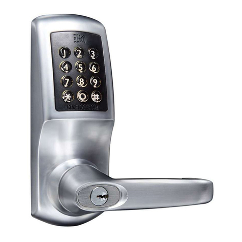
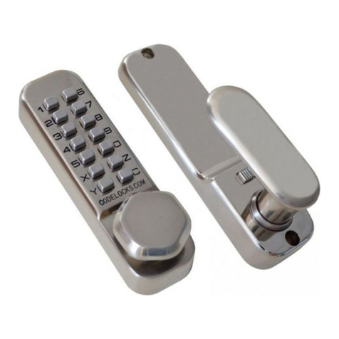
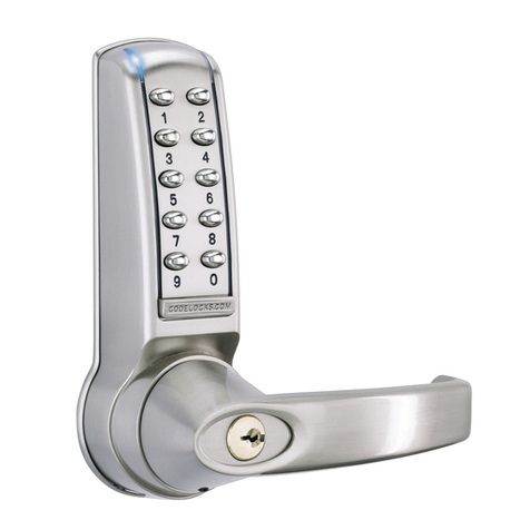
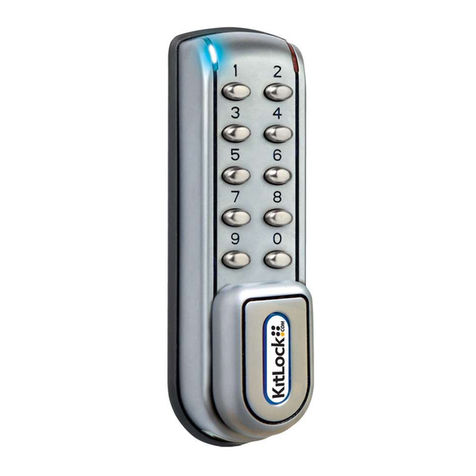
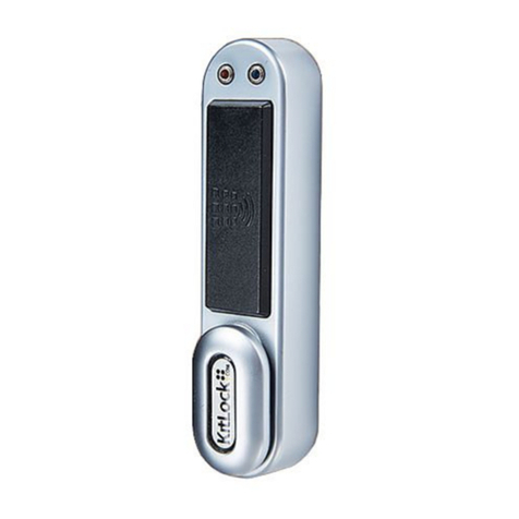
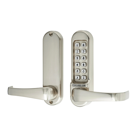
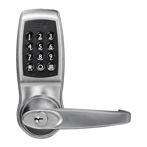
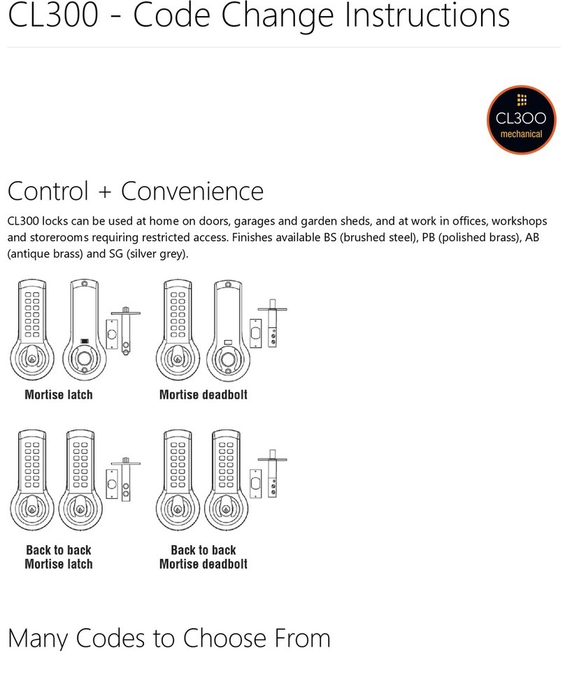
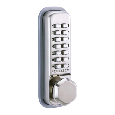
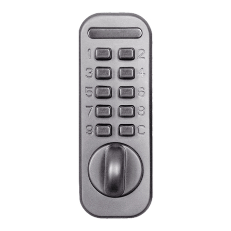
Dimensions
CL5020 LATCH FUNCTION
Outside handle and key functions as before.
Lockcase key will double-throw the deadbolt, retract the
deadbolt and retract the latchbolt without the code.
When deadbolt is thrown it denies access by code.
The anti-panic feature allows the inside handle to
simultaneously retract the latchbolt and the deadbolt preventing
people being accidentally lock in.
Installation
Installing the Anti-Panic Mortice Lock
IMPORTANT – The Anti-Panic Mortice Lock has features
which are not found in most other locks and so it is
recommended that you familiarise yourself with them.
The hand of the latchbolt is changed by removing the three
screws holding the faceplate and reversing the latchbolt.
Insert the cylinder centrally in the lockcase and fix in
position with the long bolt through the faceplate. Using the
key it should be possible to double-throw the deadbolt,
retract the deadbolt, and retract the latchbolt.
The latchbolt follower is in 2 parts, with 2 set screws visible
in each part. Determine which side of the lock will be the
outside and remove the set screws from that side. DO NOT
remove the set screws from both sides.
The outside handle will now retract the latchbolt but NOT the
deadbolt.
The inside handle will now simultaneously retract the latchbolt
AND the deadbolt if it is thrown.
This safety feature ensures that it is not possible to accidentally
lock someone in a room by throwing the deadbolt from outside.
Throwing the deadbolt will deny access to code users when appropriate.
All door locks should be installed with a degree of precision to ensure that all components are horizontally and vertically
accurate in relation to each other, and in relation to the door. Do not install the locker where it will involve cutting into a join
between the door stile and a mid-rail.
1. Lightly mark a height line on the edge and both faces of the door, and the door jamb, to indicate the top of the lock when fitted.
Mark a line down the centre of the door edge, extending above the height line and 300mm below it.
2. Hold the mortice lock template against the edge of the door with the top in line with the height line, and with the arrows in line
with the ‘Centre of Door Edge’ line. Mark the positions of the fixing screws, and the holes to be drilled for the mortice.
3. Drill the marked holes 90mm deep and form the mortice for the lock.
4. Fold the template accurately along the dotted line and tape it to the door face with the top in line with the height line, and the
fold on the door edge. Mark the centres of all the holes to be drilled. Remove the template and repeat on the other face of the
door.
5. Drill the holes from both faces of the door to improve accuracy. Do not drill right through the door as this will damage the door
when the drill breaks through.
6. Check that the 2 screws have been removed from the follower on the outside of the door.
DO NOT remove the screws from both sides of the follower.
7. Install the lock case in the door and fit the cylinder. Confirm that the key will double-throw the deadbolt, retract the deadbolt,
and retract the latchbolt.
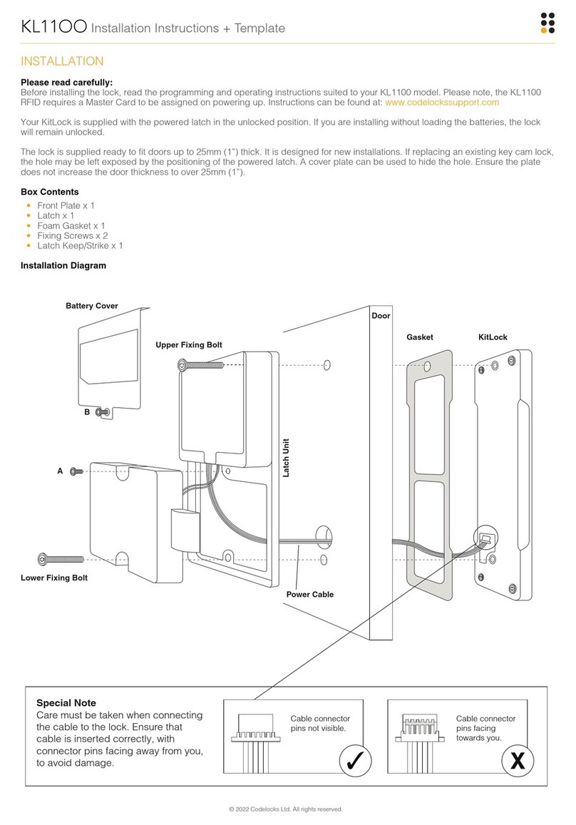
8. Fit the self-adhesive gaskets to the front and back plates. The gaskets provide friction against the door so that it is not
necessary to over-tighten the bolts to provide stability.
9. Remove the 4 socket head bolts from the back plate (2 are found under the battery cover). This releases then inside fixing
plate.
10. Cut the fixing bolts to the correct length. Measured from beneath the bolt head the length should be ‘door thickness plus
approximately 15mm’ to the nearest cutting point of the bolt.
N.B. Always cut the bolts at one of the reduced sections so as not to damage a thread. Use the cutting edge of pliers to crimp
strongly several times around the selected cutting point. The surplus end should break off quite easily.
11. According to the door thickness, insert one of the short spindles into the outside follower of the lock-case with the spring
facing out. Use the 22mm spindle for doors between 35-50mm, and the 28mm spindle for doors between 45-65mm. Insert the
longes t s pindle into the ins ide follower with the spring fac ing out.
12. Position the front plate over the spindle, passing the cable through the door. Put both parts of the back plate in position with
the spindle engaged in the follower and the cable pulled through.
13. Pass the top bolt through the door into the front plate, and then the bottom bolt, to stabilise the assembly.
14. Position the front plate over the spindle passing the cable through the door. First pass the top bolts, and then the bottom bolt,
through the inside fixing plate and into the front plate. Then fit the long spindle through the fixing plate into the inside follower.
15. Connect the cables.
16. Fit the batteries and the battery cover. Fit the cylinder cover and the handles. The inside handle should retract the latchbolt,
and the latchbolt should automatically project again when the handle is released. With the key turned 90 degrees clockwise the
outside handle should retract the latchbolt.
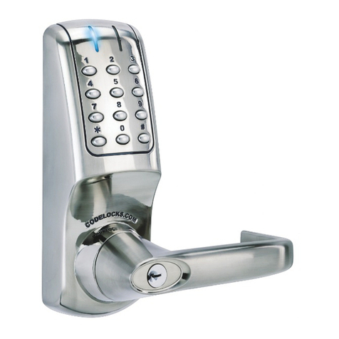
17. Enter the factory Master Code #1234. The Blue light will flash, and the handle will retract the latch.
18. Mark a vertical line on the door jamb half the door thickness away from the door stop. This gives the centre line of the strike
plate. Align the Strike Plate Template with the height line, with the arrowheads aligned with the centre line. Mark the fixing holes,
and draw around the aperture for the latchbolt and the deadbolt. Chisel out the latch aperture to 12mm deep, and the deadbolt
aperture to 22mm deep. Fix the strike plate with the top screw only and gently close the door. Ensure that the latchbolt enters its
aperture easily and holds the door without too much ‘play’. When satisfied, draw around the final position of the strike plate,
remove it, and cut a rebate to allow it to fit flash to the surface. Re-fix the strike with both screws.
