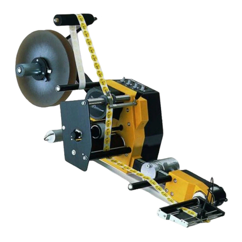
Collamat 3600 Release Note

Collamat 3600
Technical handbook
5999.515-01E
HM Collamat AG
Bodenmattstrasse 34
CH-4153 Reinach
Switzerland
Phone +41 61 756 28 28
Fax +41 61 756 29 29
www.collamat.ch

Index Page
1 Safety advices ..................................................................... 4.......
1.1 Important Warnings .............................................................. 4.......
1.2 Danger Indications ............................................................... 4
.......
1.3 Symbol descriptions .............................................................. 5.......
2Introduction ........................................................................ 6.......
2.1 General informations ............................................................. 6
.......
2.2 The labeler C3600 ............................................................... 6.......
2.2.1 Prevention of accidents ......................................................... 7.......
2.2.2 Noise suppression .............................................................. 7.......
2.2.3 Mechanical stability ............................................................. 7.......
2.3 Assembly parts ................................................................... 8
.......
3Mechanical adjustments ............................................................ 9.......
3.1 Traction unit ...................................................................... 9.......
3.1.1 Threading the labelweb ......................................................... 9.......
3.1.2 Adjustment of rewinder coupling force .......................................... 9.......
3.1.3 Readjustment of paper brake ................................................... 10.....
3.1.4 Longitudinal adjustment on the module rail ..................................... 10.....
3.2 Flap adapter ..................................................................... 11.....
3.2.1 Inclination adjustment of flap adapter ........................................... 11
.....
3.2.2 Adjustment of the pressure roller of the flap adapter ............................ 11.....
3.3 Adjustment of the optical label scanner ........................................... 12.....
3.4 Adjustment of the mechanical label scanner ...................................... 13.....
4Technical description ............................................................... 14.....
4.1 Dispenser board .................................................................. 14.....
4.1.1 Power supply ................................................................... 14.....
4.1.2 Motordriver ..................................................................... 14.....
4.1.3 Controller ....................................................................... 14
.....
4.2 Signals and connection diagrams ................................................. 15.....
4.2.1 Inputs .......................................................................... 16.....
4.2.2 Outputs ........................................................................ 16.....
4.2.3 Isolated output IFEED .......................................................... 17.....
4.2.4 Open-Collector-output IFEED ................................................... 17.....
4.2.5 Currentsource-output ........................................................... 17.....
4.3 Connection diagrams BUS X101, X102 ........................................... 18.....
4.4 Transformer wiring ............................................................... 18
.....
4.5 Connection of the mains input .................................................... 19.....
4.6 Grounding of the labeler .......................................................... 19.....
4.7 Connection of the mains output ................................................... 20.....
5999.515-01E 12.06.2007 WM Page 1/ 47

Index Page
4.8 Connection of the frontpanel ..................................................... 20.....
4.9 Motor and motorcable ............................................................ 21.....
5Firmware ........................................................................... 22
.....
5.1 Normalmode ..................................................................... 22.....
5.2 DIL-switches ..................................................................... 23.....
5.2.1 DIL-switch TEST ............................................................... 23
.....
5.2.2 DIL-switch DIR ................................................................. 23.....
6Trouble shooting ................................................................... 24.....
6.1 Fuses ............................................................................ 24.....
6.2 Status LEDs ...................................................................... 24.....
7Peripheral units and sensors ....................................................... 25
.....
7.1 Optical label scanner ............................................................. 25.....
7.2 Goods scanners .................................................................. 25.....
7.2.1 G&S measuring IR-scanner ..................................................... 25.....
7.2.2 NPN-Reflective scanner ........................................................ 25.....
7.3 Magnet adapter .................................................................. 26.....
7.4 Flatprinting unit ................................................................... 27.....
7.4.1 Flatprinter board ................................................................ 27.....
8Control signals for external units .................................................... 28
.....
8.1 How to connect a goods scanner ................................................. 28.....
9Electrical installation ................................................................ 29.....
9.1 Introduction ...................................................................... 29.....
10 Testmode ......................................................................... 31.....
10.1 Test software ................................................................... 32
.....
10.1.1 Motortest ...................................................................... 32
.....
10.1.2 Motor intervall test ............................................................. 33.....
10.1.3 BUS-signal selftest ............................................................ 33
.....
10.1.4 Signal display ................................................................. 34.....
10.1.5 DIL-switch settings ............................................................ 34.....
10.1.6 Potentiometer settings ........................................................ 34.....
10.1.7 Firmware Version ............................................................. 35
.....
11 Control of a hotstamp with the IFEED signal ....................................... 36
.....
12 Cabling and setting up ............................................................. 37
.....
12.1 Cabling ......................................................................... 37
.....
12.2 Setting up ....................................................................... 37.....
13 Version numbers .................................................................. 38.....
14 Glossary and terms ................................................................ 38.....
5999.515-01E 12.06.2007 WM Page 2/ 47

Index Page
14.1 Short cuts ....................................................................... 38.....
14.2 Signals .......................................................................... 38
.....
14.3 Terms ........................................................................... 39.....
15 Technical data .................................................................... 40.....
15.1 Dimensions - Systemdesign ..................................................... 42.....
18 Trouble shooting .................................................................. 43
.....
18.1 Trouble shooting Collamat 3600 ................................................. 43.....
18.2 Trouble shooting checklist ....................................................... 48.....
Appendix Spare parts Collamat 3600
5999.515-01E 12.06.2007 WM Page 3/ 47

1Safety advices
1.1Important Warnings
Before installing and operating the Collamat 3600 read following safety
instructions:
The labeler C3600 is exclusively determinated for labelling goods.
The installation of a Collamat 3600 has to be done by a trained specialist.
For this you have to consider the national specific regulations of
prevention of accidents
mechanical stability
construction of electrical and mechanical systems
noise suppression
Take notice to the technical data of the Collamat 3600. Especially the environment con-
ditions must be observed.
The operation of the Collamat 3600 must be done by trained personnel.
In case of non-authorized modification guarantee will fall.
Before connecting non-standard products ask your competent technical supporter.
1.2Danger Indications
The safety symbols and danger advices on the Collamat 3600 and in this manual must
strictly be observed.
Before connecting or disconnecting the labeler to or from the main, it must be
switched off.
The labeler C3600 may only be opened by authorized personnel.
Before opening the labeler C3600, it must be separated from the main power.
It exists danger of pinching hairs, jewelry, ties, clothes etc. into the traction unit
It exists danger of injury by cutting fingers in the area of the paper web.
It exists danger of injury in the area of the dancer of the unwinder of the Collamat 3600.
It exists danger of injury in the area of the paper stockcontroller of the Collamat 3600.
For operation on the Collamat 3600 the operating personnel must keep to a safely
place to prevent injury from the products being labeled.
5999.515-01E 12.06.2007 WM Page 4/ 47

1.3Symbol descriptions
ATTENTION
Indicates danger of damaging the Collamat 3600 or other system compo-
nents, with a potential consequential danger of injuries.
DANGER
Indicates an immediate hazard for persons.
DANGER
Shock hazard due to high voltage at component.
DANGER
Hazard due to high temperature component.
ATTENTION
ESD warning (Electro Static Discharge). The PC boards or component may
only be touched in an electrostatically protected environment.
NOTE
Important or additional information to Collamat 3600 or to the documentation.
5999.515-01E 12.06.2007 WM Page 5/ 47

2Introduction
2.1General informations
This technical handbook describes the construction and the function of the Collamat 3600. In
addition to the operating instructions, it contains the necessary tips and adjustments to get op-
timum use of the Collamat 3600. The descriptions of each electrical or mechanical device also
helps for quick error analysis and error elimination.
We recommend you to replace the complete electronic boards. Return it to Collamat Stralfors
AG or to its representative for repair. You can then feel sure, that the high quality standard of
the Collamat 3600 can also be guaranteed after repair.
2.2The labeler C3600
Special characteristics of the Collamat 3600:
resistant to wear, no clutch/brake-system
robust, stable
easy installation and operation due to the modular construction
quick change-over to other labelling tasks
high performance
high reliability
latest SMD-technology
high precision 2-phase steppermotor
The traction unit as well as the other peripheral assemblies are mounted on a modular rail. The
control electronics of the peripheral units are built in the units. The units are controlled and
driven by signals of the bussystem inside of the modular rail.
The operating elements for dispensing speed, predispensing, optical label scanner, as well as
the mains switch are placed right on the body of the traction unit itself. All parts are corrosion-
proof, the feedroller of the traction unit is provided with a special coating for permanent nonslip
torque transmission onto the paperweb. The rewinding force of the rewinder as well as the
braking power of the paper brake are adjustable at the traction unit from the outside.
The installation of the Collamat 3600 must be done by trained personnel. For this you have to
consider the national specific regulations of:
prevention of accidents
noise suppression
mechanical stability
construction of electrical and mechanical systems
5999.515-01E 12.06.2007 WM Page 6/ 47

2.2.1Prevention of accidents
While installing and connecting the Collamat 3600 take care that the signal cables and power
cables can't become obstacles. The cables must be placed and installed according to the na-
tional safety requirements. Take care that the signal cables are not placed beneath power
cables.
The power switch and the controll elements must easily be accessible.
2.2.2Noise suppression
The dispenser C3600 is shielded according to the CE directives. Only cables which are certifi-
cated by Collamat Stralfors AG may be used for connecting the dispenser to the peripheral
units and the mains power. Additional peripheral units must be connected to the auxiliary
mains terminal of the dispenser. These assemblies must be certificated by Collamat Stralfors
AG.
2.2.3Mechanical stability
If the Collamat 3600 is used on a movable stand, this stand must be capable to be tilt 10° in
each direction. See also following figure 1:
Figure 1: Stability of the stand
10° 10°
5999.515-01E 12.06.2007 WM Page 7/ 47

2.3Assembly parts
The assembly parts are mounted and placed on a modular rail. Following figure 2 shows these
assembly parts with their names on the modular rail:
Figure 2: Assembly parts
Legend
1. Unwinder dancer 5. Modular rail
2. Unwinder 6. Support
3. Traction unit 7. Adapter (optional with magnet)
4. Paper brake
1 2 34 5 67
5999.515-01E 12.06.2007 WM Page 8/ 47

3Mechanical adjustments
3.1Traction unit
3.1.1Threading the labelweb
Figure 3
Thread the labelweb as shown in figure 3 up to the dispensing edge and draw it out by approx.
1 m. Detach the labels from the paperweb at the drawn-out web. Then open the pinchroller by
turning the knob (1), place the paperweb over the dispensing edge and finish threading the pa-
perweb as shown in figure 3. Close the pinchroller. Adjust the side guides of the paperweb
well, leaving 0.5 mm free space to the paperweb's edge.
3.1.2Adjustment of rewinder coupling force
Figure 4
The coupling force of the rewinder is factory-set. Proceed as follows if out of adjustment:
Detach winding spindle (1) after unscrewing the M5-bolt (3). Screw M8-bolt (2) accordingly:
in= harder coupling
out= softer coupling
1
3
2
1
5999.515-01E 12.06.2007 WM Page 9/ 47

3.1.3Readjustment of paper brake
Figure 5
The braking force is factory-set to an optimum value. Should it, however, be unadjusted, read-
just it with the M3-bolt (2) in the web-end controlbox of the traction unit, from the outside.
Screw in bolt=higher braking force
Unscrew bolt=lower braking force
3.1.4Longitudinal adjustment on the module rail
Figure 6
Unscrew 4 bolts with special tool (wrench for socket head cap screws 5 mm) one half turn
(adapter only 2 bolts).
Move device, observing scale on module rail. Then tighten bolts equally.
2
5999.515-01E 12.06.2007 WM Page 10 / 47

3.2Flap adapter
3.2.1Inclination adjustment of flap adapter
Figure 7
The inclination of the flap adapter can be changed against the module rail: unscrew nut (1) with
two turns (refer to figure 7), with special hexagonal spanner (included as accessory). Push
adapter in the direction indicated by the arrow (2), turn to desired setting at ring (3). Retighten
nut (1).
The pressure force of the flap adapter without magnet or of the magnetic flap adapter is vari-
able: push in button (4) in the direction indicated by the arrow, twist for appropriate spring ten-
sion and adjust until it meets the next stop.
3.2.2Adjustment of the pressure roller of the flap adapter
Figure 8
The pressure roller of the adapter can be adjusted depending on the labels and goods:
Horizontal adjustment with the knurled nut (5)
Vertical adjustment with the hexagonal nut (6)
12 3 4
5 6
5999.515-01E 12.06.2007 WM Page 11 / 47

3.3Adjustment of the optical label scanner
Figure 9
Proceeding of the adjustment of the optical label scanner:
Switch on the Collamat 3600. Set the label scanner potentiometer to zero. Pull the labelweb so
that the gap is located below the marking 1 of the scanner. Turn the potentiometer until the red
LED on the scanner goes off. Continue pulling the labelweb until a label is located below the
scanner. Continue turning the potentiometer until the LED switches off again. The optimum
setting is at the center position of the two potentiometer settings witch turned the LED off.
Remark:
If the setting of the optical label scanner is faulty, the gap between the labels
will not be detected. After the triggering of a labelling operation, the labeler
will stop after approx. 0.75 m of the labelweb.
For transparent labels, please use the mechanical label scanner.
min. 2 mm
LED
1
Gitter
5999.515-01E 12.06.2007 WM Page 12 / 47

3.4Adjustment of the mechanical label scanner
The mechanical label scanner (not used on magnetic flap adapter) is an alternative to the opti-
cal label scanner and is mainly used for transparent labels.
1. Scanner support
2. Scanning head
3. Nut
Figure 10
Adjustment:
Place the label under the scanning head, the LED on the scanner support must be turned
on. If this is not the case, unscrew the nut on the scanning head and turn it counterclock-
wise until the LED turns on.
Turn the scanning head clockwise until the LED turns off.
Turn the scanner one quarter turn forward and retight the nut.
Place the gap between the labels under scanning head, the LED-display must be turned
on.
Note:
No adjustment is necessary on the traction unit!
2 - 6 mm
LED
1
2
3
1
2
3
5999.515-01E 12.06.2007 WM Page 13 / 47

4Technical description
4.1Dispenser board
All the electronic devices including power transformer, except of the main switch with indicator
lamp, are located on a printed board. The dimensions of the board are approximately 215 x
234 mm. Figure 11 shows the board with all the connectors and terminals.
The description is divided into power supply, motordriver, controller and firmware.
4.1.1Power supply
The power supply unit generates the two regulated voltages +12 V/1A and + 5 V/1 A for the
logic, as well as an unregulated DC voltage of approx. 40 V/3.5 A for the steppermotor. The
stabilization is done by linear voltage regulators.
4.1.2Motordriver
The driver board consists of 2 H-bridge circuits to drive the two motor phases. The phase cur-
rent is 4 A while running, and 2 A when stopped. To control the current, a chopper circuit with
20 kHz chopper-frequency is used.
Dependent on the dispensing speed the processor generates a fullstep- or a halfsteppattern.
For speeds faster than 10 m/min, the motor is driven by a fullstep- pattern.
In the case of overheating, short-circuit or malfunction the motordriver is switched off and the
red LED FAULT is illuminated. In this case the labeler must be switched off and on again.
4.1.3Controller
The single chip micro-controller H8/532 with external 32 K-Byte EPROM controls the functions
of the labelling process.
All outputs are buffered by photo-couplers.
All the inputs are pulled up to +12V with 2.2 K and are equipped with a low-pass filter.
The A/D-converter scans periodically the value of the settings of the 3 potentiometers
(R101....R103).
The control current of the label scanner is generated by a controlled current source.
5999.515-01E 12.06.2007 WM Page 14 / 47

Figure 11: Dispenser board
4.2Signals and connection diagrams
All in- and outputs are equipped with filter elements to prevent electromagnetic interference.
These components also prevent interference caused by electrostatic discharge. The interfer-
ence can lead to malfunction of the Collamat 3600. Anyway, installing the Collamat 3600 you
have to consider the rules concerning RMI and ESD to prevent these interferences. See also
chapter Cabling.
GND
GSC1
+12V
GND
LSC
+12V
TCY
+12V
GND
RDY
FEED
IFD
IFD
+12V
X48
a3
a2
a1
L1
N1 X46
96
1
F1
2AT 230V
4AT 115V
N
L
X51
F2
3.15AT
1.6AT
F3
3377
IN
X40 LNPE
X101X102
12V
5V
TEST
DIR
X104
1
2
RESET
FAULT
7605
OUT
X1
X14
SPEED PREDISP TCY
X105
X39
X36
IC2
5999.515-01E 12.06.2007 WM Page 15 / 47

4.2.1Inputs
The inputs are used to connect peripheral units and sensors. The inputs are activated while
they are pulled to GND (0 Volt). The peripheral units from Collamat Stralfors AG have NPN-
outputs to 0 Volt.
Figure 12 shows the schematic diagram of the inputs:
On: >4mA (or < 2 V)
Off: 0mA (or > 8 V)
Vmax: 24 V
Figure 12: Signal input
An input is then active, when a current of minimum 4mA is pulled to GND. The following inputs
are available:
GSC1 Goods scanner
LSC Label scanner
READYREADY-signal for peripheral units
4.2.2Outputs
The outputs are used to control peripheral units. There are three different kinds of outputs:
Isolated output
Open-Collector-output
Currentsource-output
10nF
2k2
+5 V
-
+
LM339
10k
10k
+12 V+12 V
100k
2k2
GND
IN 4k7
1n
H8/532 Input
5999.515-01E 12.06.2007 WM Page 16 / 47

4.2.3Isolated output IFEED
This output is completely isolated to the electronic circuit of the labeler. Figure 13 shows the
schematic diagram of this isolated output:
Figure 13: Isolated output IFEED
4.2.4Open-Collector-output IFEED
For better resistance against interferences, the Open-Collector-output IFEED is also equipped
with a photocoupler. Figure 14 shows the schematic diagram of the Open-Collector-output
IFEED:
Figure 14: Open-Collector-outputs
4.2.5Currentsource-output
For the IR-transmitter of the label scanner TCY, a controlled currentsource is used. Figure 15
shows the schematic diagram of the currentsource:
Figure 15: TCY-currentsource
PC355T
+
-
1n 1n
Umax.: 24 VDC
Imax: 25 mA
+5 V
PC355T
+
1n
Umax.: 24 VDC
Imax: 25 mA
+5 V
+12 V
TCY
4 IR-LEDs
OP-AMP
10k 100k
100n 10n
BCP54-16
100
LM358
PWM
H8/532
5999.515-01E 12.06.2007 WM Page 17 / 47

4.3Connection diagrams BUS X101, X102
The buscable of the peripheral units is connected to the connectors X101 or X102. The cable
must be placed inside of the module rail to prevent interferences. Figure 16 shows the position
of the buscable connectors on the dispenser board:
Figure 16
Connector X102 Connector X101
Pin Signal Pin Signal Pin Signal Pin Signal
1+12V 2+12V 1GND 2GND
3READY 4FEED 3nc. 4nc.
5LSC 6GSC1 5nc. 6nc.
7TCY 8nc. 7nc. 8TCY
9nc. 10 nc. 9GSC1 10 LSC
11 nc. 12 nc. 11 FEED 12 READY
13 GND 14 GND 13 +12V 14 +12V
4.4Transformer wiring
The secondary side of the transformer is connected to the terminals X36...X39. Both violet
wires are connected to the terminals signaled with a 7. Both orange wires are connected to the
terminals signaled with a 3. See also Figure 17:
Figure 17
X102 X101
1
1
1 2
13 14 12
14 13
X39
X36
3 3 77
violett
orange
5999.515-01E 12.06.2007 WM Page 18 / 47

The primary side of the transformer is connected to the terminals X46 and X48. Dependent to
the mains voltage the transformer is connected as shown in figure 18:
Figure 18: Transformer wiring
4.5Connection of the mains input
The powercord must be connected to the terminal X40. To prevent interferences it must be
looped through a ferrite-filter as shown in figure 19:
Figure 19
4.6Grounding of the labeler
The grounding of the module rail and of the adapter must be done to terminal X51. For this see
also figure 21.
110 V 120 V 220 V 230 V 240 V
0 = schwarz 2 = rot 4 = gelb 5 = grün 8 = grau 9 = weiss
a3
a2
a1
L1
N1
a3
a2
a1
L1
N1
a3
a2
a1
L1
N1
a3
a2
a1
L1
N1
a3
a2
a1
L1
N1 9
8
2
5
0
4
9
8
2
5
0
4
9
8
2
5
0
4
5
9
4
8
2
0
0
2
4
8
5
9
X48
X46
X48
X46
X48
X46
X48
X46
X48
X46
2 Windungen
IN
X40 LNPE
X101
X25
gelb/grün
Ferrit-Filter
braun blau
5999.515-01E 12.06.2007 WM Page 19 / 47
Other manuals for 3600
1
Table of contents
Other Collamat Label Maker manuals

Collamat
Collamat 8600 User manual

Collamat
Collamat S Series Release Note

Collamat
Collamat 8600 User manual

Collamat
Collamat 2600 User manual

Collamat
Collamat 9100 User manual

Collamat
Collamat 8600 Release Note

Collamat
Collamat Etiprint Inline User manual

Collamat
Collamat 9100 Release Note

Collamat
Collamat 7600 User manual

Collamat
Collamat 3600 User manual