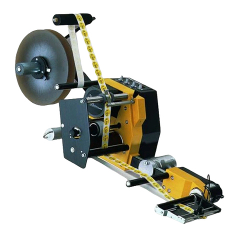
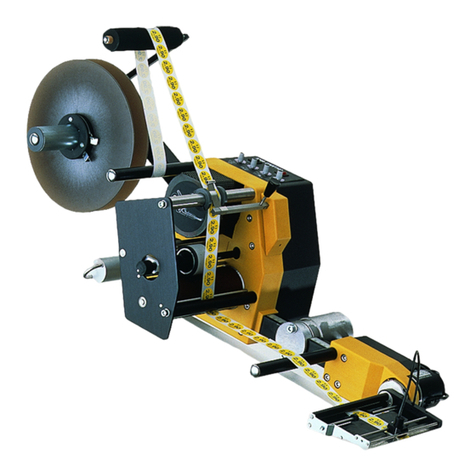
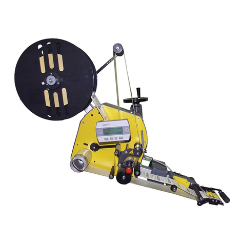
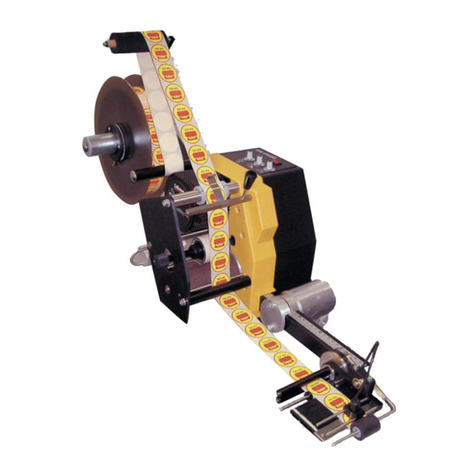
Collamat 9100 User manual

CCollamatollamat®91009100
Operating instructions
Collamat Stralfors AG CH-4147 Aesch Pfeffingerring 201 Tel +41 61 756 28 28 Fax +41 61 756 29 29
5999.550-01A

Index
page
Index 1
Important warnings 2
Symbol description 3
General information 4
Thread up of the labels 5
Midiunwinder or electric unwinder 6
Paper brake traction unit 7
Flap adapter 8
Traction roll, traction unit 9
Electric rewinder 10
Adjustment of the dancer 11
Installation of the flap adapter 12
Adjustment of the press-roll 12
Mechanical label scanner 13
Positioning of the CS mechanic goods scanning 14
Minimal goods distance 15
Servicing 16
Condensations 16
Signals 16
Glossary 17
Technical data 18
Trouble shooting checklist 21
5999.550-01A 11.08.98 WM Page 1/ 21

Important warnings
Before installing and operating the Collamat®9100 read following safety
instructions:
The Collamat®9100 labeler is exclusively decided for labelling products. It must
exclusively be controlled and driven by a 9100 monitor.
The installation of a Collamat®9100 has to be done by a trained specialist. For
this you have to consider the national specific regulations of
prevention of accidents
mechanical stability
construction of electrical and mechanical systems
noise suppression
Take notice to the technical data of the Collamat®9100. Especially the environ-
ment conditions must be observed.
The operation of the Collamat®9100 must be done by trained personnel.
In case of non-authorised modification, guarantee will fall.
Before connecting non-standard products, ask your competent technical
supporter.
Danger indications
The safety symbols and danger advices on the Collamat®9100 and in this
manual must strictly be observed.
Before connecting or disconnecting the labeler to or from the monitor 9100 the
monitor must be switched off.
The monitor and the distribution box may only be opened by authorized
personnel.
Before opening the distribution box, the monitor must be separated from the
mains power.
It exists danger of pinching hair, jewelry, ties, clothes etc. into the traction unit.
It exists danger of injury by cutting fingers in the area of the paper web.
It exists danger of injury in the area of the dancers of the rewinder and unwinder
of the Collamat®9100.
It exists danger of injury in the area of the paper stockcontroller of the Collamat®
9100.
To operate on the Collamat®9100 the operating personnel must keep to a safely
place to prevent injury by the products being labeled.
5999.550-01A 11.08.98 WM Page 2/ 21

Symbol description
ATTENTION
Indicates danger of damaging the Collamat®9100 or other sy-
stem components, with a potential consequential danger of
injuries.
DANGER
Indicates an immediate hazard for persons.
DANGER
Shock hazard due to high voltage at component.
DANGER
Hazard due to high temperature component.
ATTENTION
ESD warning (Electro Static Discharge). The PC boards or com-
ponent may only be touched in an electrostatically protected
environment.
NOTE
Important or additional information to Collamat®9100 or to the
documentation.
5999.550-01A 11.08.98 WM Page 3/ 21

General information
Special characteristics of the Collamat®9100 system:
Technical advanced design with ability to adapt to future developments in the control
system and driving technology
High performance labelling accuracy even with maximum dispensing speed and pro-
duct speed fluctuation
Resistant to wear, no clutch/brake system
Rugged construction for application in the industry
Easy handling due to modular construction
Secure, due to a simple design and operational monitoring system
Free of services, rugged and a fail-safe monitor
Monitor controllable through control signals from outside
Simple to adjust, modern menu guided operating
Easily moved between product lines with simple fitting and setting up times
Storage for 20 labelling programs
The modular system allows the addition of the peripheral appliances on a module rail.
The complete electronic operating and electronic control system for the traction unit are
installed into a modern, elegant box. The connection to the particular peripheral
appliances takes place through a connection box on the module rail. An essential ad-
vantage is the expandability of the system without extra expenditure in the basic system
itself. A micro-processed electronic system, a multiple line LCD and a neatly arranged
keyboard grant a comfortable operating of the Collamat®9100. All parts are surface
treated or made of rust resistant material. The traction unit is specially coated in order
to avoid slippage of the paper during the turning moment. The un- and rewinder, which
are equipped with an own driving motor, are provided with a electronic controlled tur-
ning moment.
The Labeler C9100
The traction unit as well as the other peripheral units are mounted on a modular rail.
The force of the paperbrake is adjustable. The tractionroller turns free while power off
for easy threading and installation of the paperweb.
The installation of the Collamat®9100 must be done by a trained
personnel. For this you have to consider the national specific
regulations of
prevention of accidents
noise suppression
mechanical stability
construction of electrical and mechanical systems
5999.550-01A 11.08.98 WM Page 4/ 21
Thread up of the labels
The labeller may only be opened by trained personnel. It contains no
parts to be handled by the operator.
The labeller contains live parts. Hazard of contact due to high voltages
of the assemblies.
The paper web will be pulled from the unwinder 2over the dancer of unwinder to the
traction unit. It will be conducted under the paper brake and pulled to the flap adapter 3
right to the dispensing edge. Now the paper web should be pulled up approx. 1mover
the dispensing edge, so that the importation backward through the flap adapter into the
traction unit would be easier. After that the paper web must be pulled through the
traction unit 1around the dancer of the rewinder up to the rewinder 4and clamped on
the rewinder core.
Before labelling, the complete paper web must be stretched to avoid label errors.
1. Traction unit 2. Midi-unwinder or electric unwinder
3. Flap adapter 4. Electric rewinder
Attention:
It exists danger of injury by cutting in the area of the paperweb.
12 34
5999.550-01A 11.08.98 WM Page 5/ 21

Midi-unwinder or electric unwinder
Pull of the holding disk 4from unwinder core 1by compressing the two handles 5.
1. Unwinder core
2. Deflection pulley
3. Dancer
4. Holding disk
5. Handles
Insert the label roll on the unwinder core 1and fix it with the handling disk 4. Thread up
the label web as shown per picture. The direction of the unwinder can be changed with
the direction switch 5, which is found behind the holding disk 4.
1. Unwinder core
2. Deflection pulley
3. Dancer
4. Holding disk
5. Direction switch
6. Label web
Note:
Adjustment of the spring force see under "Adjustment of the dancer"
1
5
43
2
1
4
3
6
2
5
5999.550-01A 11.08.98 WM Page 6/ 21

Paper brake, traction unit
Thread up the label web around the deflection pulley 1. Lift the paper brake 2. Thread
up the web between the paper brake and the brake plate under the front deflection pul-
ley. Pull it to the flap adapter. Put down again the paper brake.
1. Deflection pulley
2. Paper brake
3. Front deflection pulley
4. Brake plate
5. Label web
Note:
If the paper brake 2 is not correctly fixed, an error message takes place
at the beginning of labelling:
"Error paper traction /-end"
123
4
5
5999.550-01A 11.08.98 WM Page 7/ 21

Flap adapter
Pull the label web between the two deflection pulleys 1 and 2as well above the stop-
ping axle 3. Conduct the label web under the label scanner 5and pull up approx. 1m.
Take off the labels from the backing paper. Put the backing paper around the dispen-
sing edge 6and conduct it again under the stopping axle 3and the two guiding rolls 1
and 2.
In order to change the optical label scanner 5 transversely, the knurled screw 8 has to
be detached.
1. Deflection pulley above
2. Deflection pulley below
3. Stopping axle
4. Stop
5. Optical label scanner
6. Dispensing edge
7. Pressing roll
8. Knurled screw
9. Label web
Attention:
If the slope of the flap adapter so big, that the two paper webs between
the two deflection pulleys 1 and 2 touch each other, then the returning
backing paper has to be guided under the second deflection pulley.
785319
6
42
5999.550-01A 11.08.98 WM Page 8/ 21

Traction roll, traction unit
Turn the knurled knob 3by 90° in order to ease the back pressure roll 2at the traction
roll 1.
Right-hand version: turn clockwise
Left-hand version: turn counterclockwise
Position the back pressure roll 2in the middle of the backing paper (for this the set
screw has to be released in order to move the back pressure roll 2). Wind the backing
paper around the traction roll 1 and the back pressure roll 2 as shown per picture, re-
tention the back pressure roll.
1. Traction roll
2. Back pressure roll
3. Knurled knob
4. Deflection shaft
5. Backing paper web
Note:
If the back pressure roll 2 is not under tension an error message
appears: "Paper traction / -end"
2
1
4
5
3
5999.550-01A 11.08.98 WM Page 9/ 21

Electric rewinder
Pull out the clamp strap 3. Pull the backing paper over the dancer 1to the rewinder co-
re 2. Wind the backing paper around the rewinder core 2and fix the clamp strap 3
again.
In order to remove the backing paper pull out the clamp strap 3and take off the paper
from the rewinder core 2.
1. Dancer
2. Rewinder core
3. Clamp strap
4. Backing paper web
5. Direction switch
If the Collamat®9100 is switched on without having fixed the backing
paper, or if the backing paper is torn apart during the application, the
dancer will shoot up to the stop A. The rewinder drives to the maximum
speed and will stop after 8 rotations. It can only be restarted when the
dancer 1 is reset to the stop B (reset of the stop command). The zero
position takes place at the stop B of the rewinder, the rewinder core
does not turn anymore.
Adjustment of the spring force: see under "adjustment of he dancer".
B
A1
2
3
4
5
5999.550-01A 11.08.98 WM Page 10 / 21

Adjustment of the dancer
Spring force
The spring force has to be fixed in a way, that the backforce is not stronger than the
dancer 2 needs to turn back itself.
Adjustment of the spring force
Dismantle the housing 3 (not available at the midi-unwinder). For the adjustment push
permanent the knob 1 and turn it up to the desired spring force. Then leave the knob,
so that it remains at the new position. Reassemble the housing.
1. Knurled knob
2. Dancer
3. Housing
4. Brake shaft
(only Midi-unwinder)
Adjustment of the dancer
The adjustment of the dancer has to be done by trained personnel during the installati-
on of the system res. during the mounting of the Collamat®9100 (see technical
handbook).
A wrong adjustment leads to a lack of capacity and lack of accuracy.
4
2
1
3
5999.550-01A 11.08.98 WM Page 11 / 21

Installation of the flap adapter
The slope of the flap adapter 4can be changed against the module rail. Release the
knurled knob 1 with two turns. Extend the screen 2by hand, position the adapter 4 in
the required position and fix the knurled knob 1again.
On the spring flap adapter the required spring force can be adjusted with the cylinder
head screw 3.
Direction A: stronger
Direction B: softer
1. Knurled knob
2. Screen
3. Cylinder head screw
(adjustment of the
spring force)
4. Flap adapter
Adjustment of the press roll
The press roll of the adapter can be adjusted depending on the label and goods.
Horizontal adjustment with the knurled knob 1
Vertical adjustment with the knurled knob 2
A
B
1234
1 2
5999.550-01A 11.08.98 WM Page 12 / 21

Mechanical label scanner
For difficult labels (e.g. translucent blank PVC-labels or translucent labels with light per-
meability print) it is preferable to use the mechanical label scanner. The mechanical
scanner is mounted on the same fixation.
Only applicable on fix flap adapter and on scanning holder. This one
will be mounted separately on the module rail.
Adjustment
Mount the label scanner on the fixation. Connect the inductive proximity switch with the
LSC in the signal distribution box on the module rail. Pull up the label web as far as the
label gap will be directly under the scanning roll, then release the screw 5and turn the
inductive proximity switch 1until it is active (LED is lighting). Now pull on the label web
by hand until the scanning strap 2, res.. the scanning roll rolls on the label. Now the in-
ductive proximity switch should be passive (LED off). For safety reason turn the inducti-
ve proximity switch 1/4-turn and repeat the adjustment. Then tighten the screw 5.
1. Inductive proximity
switch with LED
2. Scanning strap
3. Housing
4. Scanning stripe
5. Screw
6. Label
12
3
4
5
6
5999.550-01A 11.08.98 WM Page 13 / 21

Positioning of the CS mechanical goods scanning
Switch on the control system. At the transmitter 1the LED shows red. Displace the
receiver 2, which is found opposite to the transmitter, until both red LED on the receiver
are no more illuminated. For an exact labelling the goods scanning should be mounted
very near of the dispensing edge. An exact positioning of the label on the goods takes
place by input of the position value on the monitor (see operating Collamat®9100). If
you increase this value the label will displace back on the goods.
Example:
1. Transmitter goods scanner
2. Receiver goods scanner
3. Conveyor belt
4. Goods
5. Press roll of the adapter
6. Label
LED
LED
GSC
1 2
max 600 mm
1
23
4
5
6
5999.550-01A 11.08.98 WM Page 14 / 21

Minimal goods distance
The minimal distance between the goods is treated differently for the speed measuring
with measuring scanner or incremental encoder.
For the measuring scanner the following figure is valid:
d = Distance between GSC1 and GSC2
x = d + 2 mm
For the speed measuring with the encoder the following figure is valid:
x = Label length + Gap + Position
When:
Gap =Distance of the labels on the paperweb
Position =Position setting of the goods scanner (minimum 10 mm)
The labelling speed with encoder follows the goods speed down to zero. The labelling is
finished after the goods have started to move again. The labeler can be stopped while
the goods are stopped with the RUN/STOP key.
x
GSC1
GSC2
d
x
5999.550-01A 11.08.98 WM Page 15 / 21

Servicing
The Collamat®9100 is free of servicing. But please note, that the appliance has to be
cleaned according on working, especially the paper dust, adhesive remainders and
colour remainders of the printing group.
It is very important to clean the paper brake and the label scanner. After each cleaning,
all paper guiding elements like rolls (exceptional the traction unit), axles and dispensing
edge, have to be sprayed with a silicon spray.
Dependent to the wear of the pinchroller it must be replaced. The description of the
exchange is written in the technical handbook of the Collamat®9100.
Condensations
ESD Electro Static Discharge
GND GrouND
LCD Liquid Crystal Display
LED Light Emitting Diode
nc not connected
RS232 standard serial data exchange
Signals
ERROR Error signal caused by an error on stopping the dispenser
FEED Isolated signal which is active during the labelling
GND GrouND
GSC Goods SCanner
HOT HOT-stamp-connection
IFEED Through photo coupler galvanic insulated FEED-signal
LLO Label LOw, signal which shows the end of the label stock
LSC Label SCanner
nc not connected
NOK Not OK
NSTPIN Non SToP IN-put
NSTPOUT Non STop OUT-put
READY Ready signal of peripheral units for the Collamat®
RWF ReWinder Full, rewinder diameter will be too big
TCY TransparenCY, current signal to the transmission diode of the label
scanner
TUNIT Traction UNIT, signal in order to the observing of the traction unit
5999.550-01A 11.08.98 WM Page 16 / 21

Glossary
Adapter: Part of the dispenser, on which the label will be dispensed by peeling the la-
bel from the backing paper (pulling on over an edge)
CE-symbols: Certificate of products "Conformité Européenne"
Collamat®:Trademark of an labelling system produced by Collamat Stralfors AG
9100:Labelling system Collamat®type 9100
Dispensing speed: Speed of the goods on which will be sticked a label
Galvanic isolated: Not conductive electrical, no contact
GSC: Goods scanner
Flap adapter: Adapter, which is bending down to be capable to dispense the labels in a
deepening.
LSC: Label scanner
LC-Display, LCD: Liquid crystal display
Machine status: Operation status of the machine. Examples: STOPPED, OK, ERROR
Midi-unwinder: Unwinder without an electric drive
Monitor: Control box containing all the electronic modules of the label dispenser
Motorstep: Way which travel a label during a motorstep
Paper brake: Brakes the paper web in front of the adapter in order to built up a defined
tensile
Pinch roller: Presses the backing paper against the traction roll for transportation
Position: Sticking position of a label on the goods
Predispensing: Predispensing of the label over the dispensing edge in stop position
Press roll: Roll on the adapter to press the label on the goods
Rewinder: Appliance to take on the empty backing paper
Speed: Dispensing speed of the label during the labelling
Start frequency: The highest allowable frequency to start a stepping motor from stop
position without loss of steps
Stop accuracy: Says how exact the label is stopped on the dispensing plate
Traction unit: Part of the labeler on which - most over a roll - a backing paper is pulled
Traction roll: It pulls on the paper web in order to dispense a label. It is driven by the
stepping motor
Unwinder: Appliance to take on and unwind the full label roll
5999.550-01A 11.08.98 WM Page 17 / 21

Technical data
Dispenser general data (standard values)
System Units C9110 C9120 C9130
Version right/left
Dispensing speed m/min 0.5-80 0.5-60 0.5-40
Min. label width mm 20
Max. width of the paperweb mm 95 160 250
Min. label length mm 10 15 20
Min. label length
@ max. dispensing speed mm 28 13 10
Stop accuracy mm @ 40 m/min ± 0.5
Minimal gap between labels for optical
scanner mm 3.0
Minimal gap between labels for mechanical
scanner mm 2.0
Max. diameter of paperroll mm 350
Max. weight of paperroll kg 20
Noise figure max. dB(A) < 70
Traction unit
System Collamat®9100
Driver 3-Phase steppermotor 500 steps
Motor voltage 120V
Max. phase current 5.0 A
Type of protection IP40
Ambient temperature +5-40 °C
Ambient humidity 15-90%, non condensing
Noise figure max. 70 dB(A) @ 1 m distance
System C9110 C9120 C9130
Weight 8.2 kg 9.0 kg 10 kg
5999.550-01A 11.08.98 WM Page 18 / 21

Midi-unwinder
Diameter of the roll core 42 mm
Max. outside diameter of roll 350 mm
Max. weight of roll 20 kg
Empty weight 4.2 kg
Spring dancer with automatic brake
Motor driven rewinder and unwinder
System Rewinder Unwinder
Diameter of the roll core 42 mm
Max. diameter of roll 350 mm
Drive current controlled DC-motor, electromagnetic brake
Electric power 24 V DC, 3A max. 24 V DC, 2A max.
Type of protection IP54
Ambient temperature +5-40 °C
Ambient humidity 15-90% non condensing
Weight 5 kg
Flap adapter
System C9110 C9120 C9130
Max. width of paperweb 95 mm 160 mm 250 mm
Weight 4.5 kg 5.0 kg 5.6 kg
Version right/left
Adapter angle ±90°, with adjustable snap-in locking
Recuperating spring force adjustable
Additional press time of adapter adjustable
Max. cadence on max. turning angle 10'000 cycles/h
Max. turning angle 15°
Ambient temperature +5-40°C
Ambient humidity 15-90% non condensing
5999.550-01A 11.08.98 WM Page 19 / 21
Other manuals for 9100
3
This manual suits for next models
1
Table of contents
Other Collamat Label Maker manuals

Collamat
Collamat 9100 User manual

Collamat
Collamat 8600 User manual

Collamat
Collamat 2600 User manual

Collamat
Collamat Etiprint Inline User manual

Collamat
Collamat 3600 User manual

Collamat
Collamat S Series Release Note

Collamat
Collamat 7600 User manual

Collamat
Collamat 9100 Release Note

Collamat
Collamat C4300 Series User manual

Collamat
Collamat 6600 Release Note