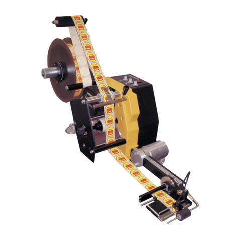
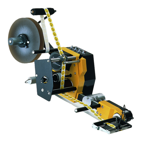
Collamat 9100 Release Note

CCollamatollamat®91009100
Technical handbook
Collamat Stralfors AG CH-4147 Aesch Pfeffingerring 201 Tel +41 61 756 28 28 Fax +41 61 756 29 29
5999.557-01A

Index page
1 Safety advices .............................................................. 6......
1.1 Important warnings ........................................................ 6......
1.2 Danger advices ............................................................ 6......
1.3 Symbol descriptions ....................................................... 7......
2 Introduction ................................................................. 8......
2.1 General information ....................................................... 8......
2.2 The Monitor ............................................................... 8......
2.3 The software .............................................................. 9......
2.4 The Dispenser ............................................................. 9......
3 The Collamat® 9100 Labeller ................................................ 10.....
3.1 Prevention of accidents .................................................... 10.....
3.2 Noise suppression ......................................................... 10.....
3.3 Mechanical stability ........................................................ 10.....
4 Assemblies .................................................................. 11.....
4.1 Installation examples ...................................................... 12.....
5 Traction unit ................................................................. 13.....
5.1 General information ....................................................... 13.....
5.2 Pinchroller ................................................................. 14.....
5.2.1 Direction of tension force ................................................ 14.....
5.2.2 Exchange of pinch roller ................................................. 15.....
5.2.3 Parallel adjustment of pinch roller ........................................ 16.....
5.3 Traction roller ............................................................. 17.....
5.3.1 Replacement of traction roller and damping disk ......................... 17.....
5.4 Rewinder and unwinder ................................................... 18.....
5.4.1 General information ..................................................... 18.....
5.4.2 Support plate ............................................................ 19.....
5.4.3 Drive .................................................................... 19.....
5.4.4 Dancer .................................................................. 19.....
5.4.5 Winder mandrel ......................................................... 19.....
5.4.6 Brake ................................................................... 19.....
5.4.7 Winder control ........................................................... 19.....
5.5 Final assembly of the winder ............................................... 20.....
5.5.1 Assembly of the dancer .................................................. 20.....
5.5.2 Assembly of the unwinder/rewinder mandrel ............................. 20.....
5.5.3 Exchange of the dancer spring ........................................... 20.....
5.6 Adjustments ............................................................... 21.....
5.6.1 Spring force of the dancer ............................................... 21.....
5999.557-01A 07.09.99 WM Page 1/ 74

Index page
5.6.2 Tension direction of the dancer .......................................... 21.....
5.6.3 Direction of action of the dancer ......................................... 22.....
5.6.4 Motor rotation direction .................................................. 22.....
5.6.5 Tension force of the motor ............................................... 22.....
5.6.6 Breaking force and time ................................................. 22.....
5.7 Arrangement and mechanical adjustment of the rewinder .................. 23.....
5.8 Arrangement and mechanical adjustment of the unwinder .................. 25.....
5.8.1 Maintenance ............................................................ 25.....
5.9 Brake ..................................................................... 26.....
5.9.1 Adjustment of brake ..................................................... 26.....
5.10 Motor brushes ............................................................ 27.....
5.11 Electrical settings ........................................................ 27.....
5.11.1 Direction of action of dancer (DANCER) ................................ 28.....
5.11.2 Motor force (TORQUE) ................................................. 29.....
5.11.3 Winder (WIND) ......................................................... 29.....
5.11.4 Adjustment of the break current ........................................ 30.....
5.11.5 TIME ................................................................... 30.....
5.11.6 BREAK ................................................................ 31.....
5.11.7 ATTN .................................................................. 31.....
5.11.8 DELAY ................................................................. 31.....
5.12 Midi-unwinder ............................................................ 32.....
5.12.1 General information .................................................... 32.....
5.12.2 Installation position and mechanical adjustment ........................ 32.....
5.13 Flap adapter ............................................................. 33.....
5.14 Support .................................................................. 33.....
5.15 Flap ...................................................................... 34.....
5.15.1 Exchange of the mirror ................................................. 35.....
5.15.2 Exchange of peeling edge .............................................. 35.....
5.15.3 Roller dispenser edge (option) .......................................... 36.....
5.16 Optical label scanner ..................................................... 37.....
5.16.1 Replacement of the sensor p.c.board ................................... 37.....
6 THE C9100 MONITOR ...................................................... 38.....
6.1 Construction ............................................................... 38.....
6.2 The control panel .......................................................... 39.....
6.3 Construction ............................................................... 40.....
6.4 Hardware ................................................................. 40.....
6.4.1 IC6 program memory, EPROM 128 Kbytes .............................. 41.....
5999.557-01A 07.09.99 WM Page 2/ 74

Index page
6.4.2 The LCD display ......................................................... 41.....
6.4.3 Adjusting the contrast .................................................... 41.....
6.4.4 Exchanging a defective LCD ............................................. 41.....
6.5 The back panel ............................................................ 42.....
6.6 The mains filter p.c.board .................................................. 43.....
6.6.1 Exchange of mains filter p.c.board ....................................... 43.....
6.7 The interface p.c.board .................................................... 44.....
6.7.1 The power supply ....................................................... 44.....
6.7.2 Fuses ................................................................... 45.....
6.7.3 Exchanging the interface p.c.board ...................................... 46.....
6.7.4 Terminals and connectors ............................................... 46.....
6.7.5 Particularities ............................................................ 46.....
6.8 The motor driver ........................................................... 47.....
6.8.1 Settings ................................................................. 47.....
6.8.2 Status indicators ......................................................... 47.....
6.8.3 Exchanging the motor driver ............................................. 48.....
6.9 The connector box 9100 ................................................... 48.....
6.9.1 Fuse F1, 5A slow blowing ................................................ 49.....
6.10 Control signals for external units .......................................... 49.....
6.10.1 FEED .................................................................. 49.....
6.10.2 FLAP .................................................................. 49.....
7 Signals and connector pin assignments ...................................... 50.....
7.1 Inputs ..................................................................... 50.....
7.1.1 Photocoupler inputs ..................................................... 50.....
7.1.2 Comparator inputs ....................................................... 51.....
7.2 Functional description of inputs ............................................ 51.....
7.2.1 Goods scanners GSC1 and GSC2 (Good SCanner) ..................... 51.....
7.2.2 Goods scanner GSC3 ................................................... 52.....
7.2.3 Control input NSTPI (NonSToP In) ....................................... 52.....
7.2.4 Control input STOP ...................................................... 52.....
7.2.5 LSC (Label SCanner) .................................................... 53.....
7.2.6 TUNIT (Traction UNIT) .................................................. 53.....
7.2.7 READY .................................................................. 53.....
7.2.8 LLO (Label LOw) ........................................................ 53.....
7.2.9 RWF (ReWinder Full) .................................................... 53.....
7.3 Outputs ................................................................... 53.....
7.3.1 Isolated outputs ......................................................... 53.....
5999.557-01A 07.09.99 WM Page 3/ 74

Index page
7.3.2 Open-Collector outputs .................................................. 54.....
7.4 Functional description of the outputs ....................................... 55.....
7.4.1 Mode indicator RUN ..................................................... 55.....
7.4.2 Warning signal NOK (Not OK) ........................................... 55.....
7.4.3 Error signal ERROR ..................................................... 55.....
7.4.4 Connection of a signalisation to the monitor .............................. 55.....
7.4.5 Signal FEED, IFEED .................................................... 56.....
7.4.6 Flap adapter signal FLAP ................................................ 56.....
7.4.7 Steppermotor clock CLOCK ............................................. 56.....
7.4.8 Control output NSTPO (NonSToP Out) .................................. 56.....
7.5 Monitor C9100 Connector layouts ......................................... 57.....
7.5.1 Connector X3, DISPENSER ............................................. 57.....
7.5.2 Connector X5, GSC ..................................................... 58.....
7.5.3 Connector X7, CONTROL SIGNALS ..................................... 58.....
7.6 How to connect a goods scanner .......................................... 59.....
8 Nonstop labelling ............................................................ 60.....
8.1 Setting up of the Nonstop mode ........................................... 61.....
9 Speed measuring ........................................................... 62.....
9.1 Incremental encoder ....................................................... 62.....
9.2 Measuring goods scanner ................................................. 62.....
10 Motor and motorcable ...................................................... 63.....
10.1 Motorcable ............................................................... 63.....
10.2 Motor wiring .............................................................. 63.....
11 Control signals for external devices ......................................... 64.....
11.1 Control of a Hotstamp with the IFEED signal .............................. 64.....
11.2 Control of the flap adapter ................................................ 65.....
12 Testing the monitor with the diagnostic connector ........................... 66.....
13 Cabling and setting up ..................................................... 66.....
13.1 Cabling .................................................................. 67.....
13.2 Setting up ................................................................ 67.....
14 Password .................................................................. 68.....
14.1 By keyboard ............................................................. 68.....
14.2 By keyswitch ............................................................. 68.....
15 Fuses ...................................................................... 69.....
16 Glossary ................................................................... 69.....
16.1 Short cuts ................................................................ 69.....
16.2 Signals ................................................................... 69.....
5999.557-01A 07.09.99 WM Page 4/ 74
Index page
16.3 Terms .................................................................... 70.....
17 Technical data ............................................................. 71.....
18 Trouble shooting checklist .................................................. 74.....
5999.557-01A 07.09.99 WM Page 5/ 74

1Safety advices
1.1Important warnings
Before installing and operating the Collamat®9100 read the following
safety instructions.
The Collamat®9100 labeller is exclusively intended for labelling goods. It must
exclusively be controlled and driven by a C9100 monitor.
Install the Collamat®9100 only by a trained specialist considering the national
specific regulations of
prevention of accidents
mechanical stability
construction of electrical and mechanical systems
noise suppression
Take notice of the technical data of the Collamat®9100. Especially the environ-
ment conditions must be observed.
Operate the Collamat®9100 only by trained personnel.
In case of non-authorized modifications the guarantee will become void.
Before connecting non-standard products, ask your competent technical
supporter.
1.2Danger advices
The safety symbols and danger advices on the Collamat®9100 and in this man-
ual must strictly be observed.
Switch the monitor C9100 off before connecting or disconnecting the labeller
to or from the monitor C9100.
Only authorized personnel may open the monitor and the connector box.
Disconnect the monitor from the mains before opening the connector box.
Danger of pinching hair, jewelry, ties, clothes etc. into the traction unit !
Danger of injury by cutting fingers in the paper zone !
Danger of injury in the dancer roller zone of the Collamat®9100 rewinder and
unwinder !
Danger of injury in the case of non-expert use of the Collamat®9100 paper
stock control !
When operating the labeller, the operating personnel must keep to a safe loca-
tion to prevent injury by the products being labeled.
5999.557-01A 07.09.99 WM Page 6/ 74

1.3Symbol descriptions
ATTENTION
Danger to damage the Collamat®9100 or other system compo-
nents, with a potential consequential danger of injuries.
DANGER
Imminent hazard for persons.
DANGER
Shock hazard due to high voltage at component.
DANGER
Hazard of contact injury due to high component temperature.
ATTENTION
ESD (ElectroStatic Discharge) warning. The p.c.boards or other
components may only be touched in an electrostatically pro-
tected environment.
NOTE
Important or additional information to Collamat®9100 or its
documentation.
5999.557-01A 07.09.99 WM Page 7/ 74

2Introduction
2.1General information
This Technical Manual describes design and function of the Collamat®9100. In addition
to the Operating Instructions, it contains the settings and notes necessary to get opti-
mum use of the Collamat®9100. The descriptions of each electrical or mechanical as-
sembly also help for quick error analysis and trouble-shooting.
We recommend to replace p.c.boards always as complete units returning them to Colla-
mat Stralfors or its representative for repair to be sure that the high quality standard of
the Collamat®9100 can also be guaranteed after any repair.
Special characteristics of the Collamat®9100:
resistant to wear, no clutch/brake-system
rugged
easy installation and operation due to modular design
easy to operate due to up-to-date menu operated software
quick change-over to other labelling tasks
high performance
high reliability and accuracy
latest SMD-technology
high precision 3-phase steppermotor
2.2The Monitor
The power supply and the electronic control are built into a stable metal casing. All pe-
ripherals are connected to a connector box connected to the monitor back panel by one
single D-sub-connector. A large heatsink allows to operate the monitor without addi-
tional fan. The control (monitor) can be mounted in various positions.
The monitor contains the following assemblies:
Noise filter with voltage selector
The noise filter keeps EMI outside to prevent any interference with the electronic
control and also prevents EMI to be transmitted to the mains supply. The voltage se-
lector allows versatile adaptation of the power supply to different mains voltages.
Transformer
Supplies the power for all components of the Collamat®9100.
Interface p.c.board
The interface p.c.board connects the motor driver to the power supply and to the
controller. The electronic part of the power supply is also installed on the interface
p.c.board which shapes all input and output signals to and from the controller.
5999.557-01A 07.09.99 WM Page 8/ 74

Motor Driver
The 3-phase motor driver is a standard assembly of a leading stepper motor. It ener-
gizes the stepper motor. The step rate is adjustable from 200 up to 1000 steps per
revolution. Standard setting is 500 steps per revolution.
Controller p.c.board
The controller p.c.board comprises a Hitachi H8/532 microcontroller, EPROM with
software, LC-display and short-stroke keyboard. The controller p.c.board controls all
labelling sequences, the LC-display, the keyboard and the nonvolatile memory.
The LC-display has four lines with 20 characters each and a background illumination.
The controller p.c.board combines front panel and controller in one component.
2.3The software
The controlling software of the Collamat®9100 is stored in the EPROM (firmware) and
has the following features:
Modern user interface
6 digits preset and batch counter
Adjustable label length dependent suppression of label scanner signal to detect
transparent or preprinted labels
Adjustable goods speed and length dependent scanner signal suppression after
labelling
Programmable adjustment of labelling position on the goods
Programmable adjustment of predispensing
Multiple labelling with electronic setting of gap between labels
Automatic adaptation of dispensing speed by measuring the goods speed by light
barrier or incremental encoder
Storage of 32 labelling programs
Memory protection by access password
Two user levels
Monitoring of label stock and out-of-label, end of paper web, open roller in traction
unit, motor driver OK-signal
Nonstop mode with two Collamat®9100 systems
Multilingual user display
Automatic label scanner adjustment
Full operability during labelling
All peripherals program-controlled - no potentiometers and switches necessary
2.4The Dispenser
The traction unit as well as the other peripherals are mounted on a module rail. All parts
are surface treated to protect from corrosion. The special coating of the traction unit
roller affords permanent torque transmission to the paper web without slip. The force of
the paper web brake is adjustable. The traction roller can be easily turned by hand dur-
ing Power OFF for easy threading and installing the paper web.
5999.557-01A 07.09.99 WM Page 9/ 74

3The Collamat®9100 Labeller
The Collamat®9100 must be installed by trained personnel considering the following
national specific regulations:
Prevention of accidents
Noise suppression
Mechanical stability
Construction of electrical and mechanical systems
3.1Prevention of accidents
When installing and connecting the C9100 monitor and labeller pay attention that the
signal and power cables cannot become stumble obstacles. Lay the cables according to
the national safety regulations. Signal cables must not be placed in close proximity to
power cables.
3.2Noise suppression
For radio interference suppression the C9100 labeller and monitor are shielded accord-
ing to the CE directives. Only cables approved by Collamat Stralfors are allowed to be
used to connect the monitor to labeller and mains. Additional peripherals have to be
connected only to the mains socket of the monitor. These devices must be approved by
Collamat Stralfors.
3.3Mechanical stability
If the Collamat®9100 is used on a movable stand, this stand must be capable to be
tilted by 10° in each direction. See Figure 1:
Figure 1: Mechanical stability of C9100 labeller stand
10° 10°
5999.557-01A 07.09.99 WM Page 10 / 74

4Assemblies
In the following the various assemblies, their adjustment and maintenance are de-
scribed. First an overall view of the labeller.
The assemblies are mounted on a module rail. Figure 2 shows these assemblies with
their designations on the module rail:
Figure 2: Assemblies
Legend for assemblies
1. Rewinder
2. Unwinder
3. Modular rail
4. Connector box
5. Traction unit
6. Support
7. Flat printing unit (optional)
8. Adapter
1 2 3 6 7 8
45
5999.557-01A 07.09.99 WM Page 11 / 74

4.1Installation examples
Due to the modular design of the Collamat®9100 there is nearly no limit in variations of
the installation. But for best results in labelling, the following figures show installation
examples of constructions which do their work successfully:
Figure 3: 1st example
Figure 4: 2nd example
Figure 5: 3rd example
The threading of the paper web, the adjustment of the paper brake and
adapter are described in the Operating Instructions of the Collamat®
9100 labeller.
5999.557-01A 07.09.99 WM Page 12 / 74

5Traction unit
5.1General information
The traction unit can be used both for right- and left-hand versions of the labeller.
Figure 6: Traction unit
Legend for traction unit
1. Paper break
2. Pinch roller
3. Traction roller
4. Stepper motor
5. Paper web guide
6. Module rail
The direction of rotation of the traction roller is set by programming the monitor.
More information see Operating Instructions MONITOR C8600/C9100,
chapter CONFIGURATION, menu DIRECTION OF ROTATION.
Install the paper web guides in position Afor right-hand version, in position Bfor left-
hand version.
B
A
1
4 23
5
6
5999.557-01A 07.09.99 WM Page 13 / 74

5.2Pinchroller
5.2.1Direction of tension force
The direction of the tension force of the left- and right-hand version are opposite to
each other. If the direction of the tension force is not correct, hits of the rewinder to the
paper web may open the traction unit.
Procedure
Slacken locking screw 2, remove, turn, reengage and screw down knurled washer 1.
Letter 'L' or 'R' defines left- or right-hand version, respectively. Standard version is 'R'.
Figure 7: Direction of the tension force
Legend
1. Knurled disk
2. Locking screw
3. Eccentric pinch roller shaft
4. Pinch roller
5. Adjustment flange
6. Traction roller
1
2
3
4
5
6
5999.557-01A 07.09.99 WM Page 14 / 74

5.2.2Exchange of pinch roller
The pinch roller is a part subject to wear. Its wearing time is stress-dependent. It is good
practice to select a paper web wider than the pinch roller to avoid wear when the pinch
roller runs directly on the traction roller.
Procedure
Disassemble and remove front panel 1together with eccentric pinch roller shaft 2. Do
not slacken fixing screw 3. Slacken locking screw 4and pull off pinch roller 5. Attach
new pinch roller 5, tighten locking screw 4, slide in and reassemble front panel 1. Then
check parallelism with pinch roller.
Figure 8: Pinchroller
Legend
1. Front panel
2. Eccentric pinch roller shaft
3. Fixing screw of knurled knob
4. Locking screw with hexagon socket
5. Pinch roller
6. Traction roller
The parallelism adjustment of the pinch roller is described in the follow-
ing chapter.
1
2
3
45
6
5999.557-01A 07.09.99 WM Page 15 / 74

5.2.3Parallel adjustment of pinch roller
The parallelism of the pinch roller with the traction roller is decisive for the stability of
the paper transport. If the rollers are not in parallel the paper web will be transported
obliquely through the traction unit resulting in a lateral force on the paper web which
forces the web to shift on the dispensing edge and the labels to be dispensed obliquely.
Procedure
Release and shift pinch roller 2to the left, slacken screw 7on right adjusting flange 6,
turn adjustment flange 6by means of 3 mm mandrel 9appropriately.
Retighten screw 7and shift pinch roller 2to the right. Slacken clamping screw 7on left
adjusting flange 5and adjust it with the same pressure as the right adjusting flange 6.
Tighten screw 7, reposition and lock pinch roller 2in center position of traction roller 8.
Figure 9: Parallelism of pinch roller with traction roller
Legend
1. Front panel 6. Adjusting flange, right
2. Pinch roller 7. Clamping screw
3. Eccentric pinch roller shaft 8. Traction roller
4. Support plate 9. Mandrel
5. Adjusting flange, left
In new traction units the parallelism of the pinch roller to the traction
roller is already correctly adjusted by Collamat Stralfors.
7
9
152364
8
5999.557-01A 07.09.99 WM Page 16 / 74

5.3Traction roller
5.3.1Replacement of traction roller and damping disk
Procedure
Remove front panel 1together with pinch roller 9. Unscrew stud bolt 7and remove trac-
tion roller 3from stepper motor-shaft 5. Remove securing ring 8. Remove traction roller
3from roller shaft 4and replace the damping disk 6.
Reassemble the traction unit in reverse order. Tighten stud bolt only after assembly of
front panel.
Figure 10: Replacement of traction roller
Legend
1. Front panel 6. Damping disk
2. Suport plate 7. Stud bolt
3. Traction roller 8. Securing ring
4. Roller shaft 9. Pinch roller
5. Stepper motor 10. Ball bearing
It is important that the traction roller is adjusted with an axial play of
0.3 - 0.4 mm between ball bearing 10 and collar of roller shaft 4.
0.3-0.4
7 6 9 8 10
14325
5999.557-01A 07.09.99 WM Page 17 / 74

5.4Rewinder and unwinder
5.4.1General information
Rewinder and unwinder (= winder) with motor drive are intended to automatically wind
or unwind the paper web of the COLLAMAT 9100 labellers. The winder is powered with
24 VDC. A deviation of the dancer roller starts automatically the winder motor. The
winding speed is electronically controlled as a function of the dancer roller position. At
the end of the paper web or upon paper web break, the motor is stopped automatically
after some revolutions to prevent an uncontrolled run-up of the winder. Thickness of the
wound roll and direction of action of the dancer roller can be adapted by plug-in jumpers
on the electronic winder system. The direction of rotation can be switched over from
outside. Rewinder and unwinder distinguish themselves only by dancer roller and
winder mandrel.
Design
Legend
1. Unwinder
dancer roller
2. Rewinder dancer
3. Knurled knob for
dancer position
4. Toothed belt
5. Brake
6. Winder mandrel
7. Lateral disk
8. Support plate
9. Clamp
10. Dancer spring
11. DC motor
12. Motor brush
13. Cover
14. Winder control
15. Direction of rotation
toggle switch
16 Spring adjust
Figure 11: Winder
1
2
3
4
5
6
7
8
9
15
13
14
11
12
10
16
5999.557-01A 07.09.99 WM Page 18 / 74

5.4.2Support plate
The assembly is mounted on a rigid support plate 8fixing the winder on the module rail
in a stable way. A cover 13 with rubber sealing protects the winder control 14 from dirt
and humidity.
5.4.3Drive
The winder mandrel 6is driven by a current-controlled DC motor 11 via a toothed belt 4.
To prevent the winding from after-running the winder mandrel is braked with free dancer
roller by brake 5. The DC motor is equipped with exchangeable brushes 12.
5.4.4Dancer
The dancer roller arm has two tasks. On the one hand it represents a paper web stock
for rapid supply or take-up of the paper web, on the other hand it signalizes its position
to the winder control by optical sensors. With adjustable spring force, it stabilizes the
tension applied to the paper web. The cooperation of the dancer roller with the winder
control and the winder motor provides a controlled paper supply or take-up. Two differ-
ent dancer roller types 1 or 2are available for rewinders and unwinders, respectively.
5.4.5Winder mandrel
The winder mandrels 6of rewinder and unwinder are also different. The mandrel of the
rewinder is designed to take up a clamping bow which provides a sure but well detach-
able connection of the empty paper web with the mandrel.
The winder mandrel can be provided additionally with a clamping core for paper rolls
with 3" core diameter (76.2 mm). The clamping core is intended to correctly transmit the
torque to the paper roll.
On request, also clamping cores with other diameters are available.
5.4.6Brake
The winder mandrel 6is braked by a electromagnetic brake. This brake is activated by
the winder control 14 at the moment when the dancer runs free, after detection of a bro-
ken paperweb or when the motor stands still. The breaking force and breaking time can
be adjusted.
5.4.7Winder control
The winder control 14 controls the whole winding process controlling the DC motor 11
as a function of the dancer position which is optically measured and electrically
weighted. The winder control also controls the electromagnetic brake 5.
5999.557-01A 07.09.99 WM Page 19 / 74
Other manuals for 9100
3
Table of contents
Other Collamat Label Maker manuals

Collamat
Collamat S Series Release Note

Collamat
Collamat C4300 Series Release Note

Collamat
Collamat 3600 User manual

Collamat
Collamat 3600 Release Note

Collamat
Collamat Etiprint Inline User manual

Collamat
Collamat 8600 User manual

Collamat
Collamat 6600 Release Note

Collamat
Collamat 7600 User manual

Collamat
Collamat 8600 Release Note

Collamat
Collamat 9100 Release Note