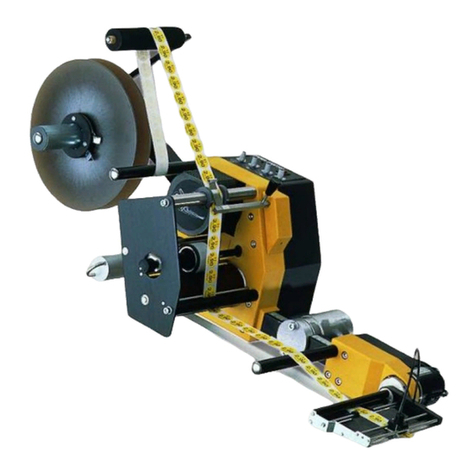
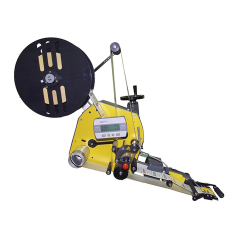
Collamat 8600 Release Note

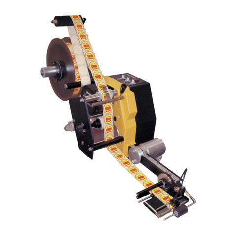
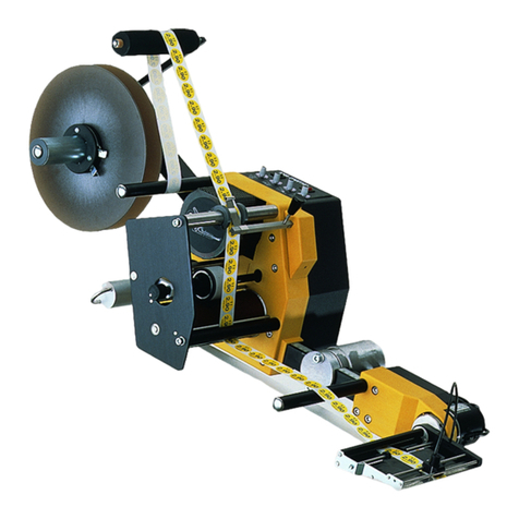
Collamat 8600
Technical handbook
5999.545-01G
HM Collamat AG
Bodenmattstrasse 34
CH-4153 Reinach
Switzerland
Phone +41 61 756 28 28
Fax +41 61 756 29 29
www.collamat.ch

Index page
1 Safety advices ..................................................................... 4.......
1.1 Important warnings ............................................................... 4.......
1.2 Danger indications ............................................................... 4.......
1.3 Symbol descriptions .............................................................. 5.......
2 Introduction ........................................................................ 6.......
2.1 General informations ............................................................. 6.......
2.2 The Monitor ...................................................................... 6
.......
2.3 The Firmware .................................................................... 7.......
2.4 The Dispenser ................................................................... 7
.......
3 The Collamat 8600 Labeller ........................................................ 8
.......
3.1 Prevention of accidents .......................................................... 8.......
3.2 Noise suppression ................................................................ 8.......
3.3 Mechanical stability ............................................................... 8.......
4 Assemblies ......................................................................... 9.......
5 Mechanical adjustments ............................................................ 10
.....
5.1 Traction unit ...................................................................... 10.....
5.1.1 Threading the label web ........................................................ 10
.....
5.1.2 Adjustment of rewinder coupling force .......................................... 10
.....
5.1.3 Readjustment of paper brake ................................................... 11.....
5.1.4 Longitudinal adjustment on the module rail ..................................... 11.....
5.2 Flap adapter ..................................................................... 12.....
5.2.1 Inclination adjustment of flap adapter ........................................... 12.....
5.2.2 Adjustment of the pressure roller of the flap adapter ............................ 12.....
5.2.3 Adjustment of the optival label scanner ......................................... 13.....
5.2.4 Adjustment of the mechanical label scanner .................................... 14
.....
6 The Monitor C8600 ................................................................. 15.....
6.1 Construction ...................................................................... 15
.....
6.2 The control panel ................................................................. 16
.....
6.3 Construction ...................................................................... 17.....
6.4 Hardware ........................................................................ 17.....
6.4.1 Firmware memory IC6, EPROM 128 Kbytes .................................... 18.....
6.4.2 The LCD-Display ............................................................... 18.....
6.4.3 Adjusting the contrast .......................................................... 18
.....
6.4.4 Exchanging a defective LCD ................................................... 18.....
6.5 The backpanel ................................................................... 19
.....
6.6 The mains filter board ............................................................ 20
.....
6.6.1 Exchange of the mains filter board .............................................. 20.....
6.7 The Interfaceboard ............................................................... 21.....
6.7.1 The power supply .............................................................. 21.....
6.7.2 Fuses .......................................................................... 22.....
6.7.3 Exchange of the interfaceboard ................................................ 23.....
5999.545-01G 13.06.2007 WM Page 1/ 65

Index page
6.7.4 Terminals and connectors ...................................................... 23.....
6.7.5 Particulars ...................................................................... 23.....
6.8 The motor driver .................................................................. 24.....
6.8.1 Settings ........................................................................ 24.....
6.8.2 Status indicators ............................................................... 24.....
6.8.3 Exchange of the motordriver .................................................... 25.....
6.9 Traction unit C8600 .............................................................. 25
.....
6.10 Control signals for external units ................................................ 26.....
6.10.1 FEED ......................................................................... 26
.....
6.10.2 READY ....................................................................... 26
.....
7 Signals and connector pin assignments ............................................ 27.....
7.1 Inputs ............................................................................ 27.....
7.1.1 Photocoupler inputs ............................................................ 27.....
7.1.2 Comparator inputs .............................................................. 28.....
7.2 Functional description of the inputs ............................................... 28
.....
7.2.1 Goods scanner GSC1 and GSC2 (Good SCanner) ............................. 28.....
7.2.2 Goods scanner GSC3 .......................................................... 29
.....
7.2.3 Control input NSTPI (NonSToP In) .............................................. 29
.....
7.2.4 Control input STOP ............................................................. 29.....
7.2.5 LSC (Label SCanner) ........................................................... 30.....
7.2.6 TUNIT (Traction UNIT) .......................................................... 30.....
7.2.7 READY ......................................................................... 30.....
7.2.8 LLO (Label LOw) ............................................................... 30.....
7.3 Outputs .......................................................................... 30.....
7.3.1 Isolated outputs ................................................................ 30
.....
7.3.2 Open-Collector outputs ......................................................... 31.....
7.4 Functional description of the outputs ............................................. 32
.....
7.4.1 Mode indicator RUN ............................................................ 32
.....
7.4.2 Warning signal NOK (Not OK) .................................................. 32.....
7.4.3 Error signal ERROR ............................................................ 32.....
7.4.4 Connection of a signalisation to the monitor .................................... 32.....
7.4.5 Signal FEED, IFEED ........................................................... 33.....
7.4.6 Steppermotor clock CLOCK .................................................... 33
.....
7.4.7 Control output NSTPO (NonSToP Out) ......................................... 33.....
7.5 Connector layouts of the monitor C8600 .......................................... 34
.....
7.5.1 Connector X3, DISPENSER .................................................... 34
.....
7.5.2 Connector X7, CONTROL SIGNALS ........................................... 35.....
7.6 Connector layouts traction unit C8600 ............................................ 36.....
7.6.1 Connector X101, X102 BUS .................................................... 36.....
7.7 Connection diagram .............................................................. 37.....
7.8 How to connect a goods scanner ................................................. 38.....
5999.545-01G 13.06.2007 WM Page 2/ 65

Index page
7.9 Goods scanners .................................................................. 39.....
7.9.1 Speed measuring CS IR goods scanner ........................................ 39.....
7.9.2 NPN Reflexscanner, Lightbeam scanner ........................................ 39.....
7.10 Optical label scanner ............................................................ 39.....
7.11 Signalcable connection ......................................................... 40.....
7.12 Adapter with magnet ............................................................ 41.....
7.13 Flatprinter board ................................................................ 42
.....
8 Nonstop labelling ................................................................... 43.....
8.1 Proceeding ....................................................................... 43
.....
8.2 Setting up of the Nonstop mode .................................................. 44
.....
9 Speed measuring .................................................................. 45.....
9.1 Incremental encoder .............................................................. 45.....
9.2 Measuring goods scanner ........................................................ 46.....
10 Motor and motorcable ............................................................. 47.....
10.1 Motorcable ...................................................................... 47
.....
10.2 Connection of the motorcable ................................................... 47.....
11 Control of external devices ........................................................ 48
.....
11.1 Control of a Hotstamp with the IFEED signal .................................... 48
.....
12 Monitortest with a diagnostic connector ........................................... 49.....
13 Cabling and setting up ............................................................ 49.....
13.1 Cabling ......................................................................... 50.....
13.2 Setting up ....................................................................... 50.....
14 Password ......................................................................... 51.....
14.1 By keyboard .................................................................... 51.....
14.2 By keyswitch .................................................................... 51
.....
15 Fuses ............................................................................. 52.....
16 Glossary .......................................................................... 52
.....
16.1 Short cuts ....................................................................... 52
.....
16.2 Signals .......................................................................... 52.....
16.3 Terms ........................................................................... 53.....
17 Technical data .................................................................... 54.....
17.1 Dimensions - systemdesign ..................................................... 57.....
18 Troubleshooting ................................................................... 59
.....
18.2 Trouble shooting checklist ....................................................... 64.....
5999.545-01G 13.06.2007 WM Page 3/ 65

1Safety advices
1.1Important warnings
Before installing and operating the Collamat 8600 read following safety
instructions.
The Collamat 8600 labeler is exclusively determinated for labelling goods. It must ex-
clusively be controlled and driven by a monitor C8600.
The installation of a Collamat 8600 has to be done by a trained specialist. For this you
have to consider the national specific regulations of
prevention of accidents
mechanical stability
construction of electrical and mechanical systems
noise suppression
Take notice to the technical data of the Collamat 8600. Especially the environment
conditions must be observed.
The operation of the Collamat 8600 must be done by trained personnel.
In case of non-authorized modification, guarantee will fall.
Before connecting non-standard products, ask your competent technical supporter.
1.2Danger indications
The safety symbols and danger advices on the Collamat 8600 and in this manual must
strictly be observed.
Before connecting or disconnecting the labeler to or from the monitor C8600 the moni-
tor must be switched off.
The monitor and the distribution box may only be opened by authorized personnel.
Before opening the distribution box, the monitor must be separated from the mains
power.
It exists danger of pinching hair, jewelry, ties, clothes etc. into the traction unit.
It exists danger of injury by cutting fingers in the area of the paper web.
It exists danger of injury in the area of the dancers of the rewinder and unwinder of the
Collamat 8600.
It exists danger of injury in the area of the paper stockcontroller of the Collamat 8600.
To operate on the Collamat 8600 the operating personnel must keep to a safely place
to prevent injury by the products being labeled.
5999.545-01G 13.06.2007 WM Page 4/ 64

1.3Symbol descriptions
ATTENTION
Indicates danger of damaging the Collamat 8600 or other system components,
with a potential consequential danger of injuries.
DANGER
Indicates an immediate hazard for persons.
DANGER
Shock hazard due to high voltage at component.
DANGER
Hazard due to high temperature component.
ATTENTION
ESD warning (Electro Static Discharge). The PC boards or component may only
be touched in an electrostatically protected environment.
NOTE
Important or additional information to Collamat 8600 or to the documentation.
5999.545-01G 13.06.2007 WM Page 5/ 64

2Introduction
2.1General informations
This technical handbook describes the construction and the function of the Collamat 8600. In ad-
dition to the operating instructions, it contains the necessary tips and adjustments to get optimum
use of the Collamat 8600. The descriptions of each electrical or mechanical device also helps for
quick error analysis and error elimination.
We recommend you to replace the complete electronic boards. Return it to HM Collamat AG or to
its representative for repair. You can then feel sure, that the high quality standard of the Collamat
8600 can also be guaranteed after a repair.
Special characteristics of the Collamat 8600:
resistant to wear, no clutch/brake-system
robust, stable
easy installation and operation due to the modular construction
simple to operate due to the menu operated software
quick change-over to other labelling tasks
high performance
high reliability
latest SMD-technology
high precision 3-phase steppermotor
2.2The Monitor
The power supply and the controller electronics are built into a stable metallic case. All peripheral
modules are connected to a connector box which is connected to the backpanel of the monitor by
one single D-sub-connector. A well dimensioned heatsink allows the operating of the monitor with-
out additional fans. The monitor may be mounted in various positions.
The monitor contains following parts:
Noisefilter with voltage selector
The noisefilter keeps RMI outside, so it may not interfere with the controller electronics. It also
prevents outgoing RMI to the mains supply. The voltage selector allows versatile adaptation of
the powersupply to different mains voltages.
Transformator
This component gives the energy for all the components of the Collamat 8600
Interfaceboard
The interfaceboard connects the motordriver to the power supply and to the controller. It con-
tains also all the electronics of the power supply. The interfaceboardshapes all the input- and
outputsignals to and from the controller.
5999.545-01G 13.06.2007 WM Page 6/ 64

Motordriver
The 3-phase motordriver is a standard component of a leading motor and motordriver manu-
facturer. The driver gives the power to the steppermotor. The step-rate may be adjusted from
200 up to 1000 steps per revolution. Standard in the Collamat 8600 are 500 steps per
revolution.
Controllerboard
It is built up with a Hitachi H8/532 microcontroller, EPROM with firmware, LC-Display and flat-
panel keyboard. The controllerboard controls all the labelling sequences, the LC-Display, the
keyboard and the nonvolatile memory.
The LC-Display has four lines with 20 characters each and a backlight illumination. The con-
trollerboard is the frontpanel and the controller in one part.
2.3The Firmware
The firmware of the Collamat 8600 has following features:
Modern human interface
6 digits preselect and goods counter
Adjustable suppression of the label scanner signal in relation to the label length to detect
transparent or preprinted labels
Adjustable signal suppression of the goods scanner in relation to the goods speed and length
after labelling
Programmable adjustment of the labelling position on the goods
Programmable adjustment of the predispensing
Multiple labelling functions with adjustable distance of the gap between the labels
Automatic capture of the labelling speed by measuring the transportation speed of the goods
with speed measuring photocells or incremental encoder
20 program memories
Protection of the memories by password access
Two user levels
Supervision of the labelstock and out of label, end of paperweb, not closed pinchroller in the
traction unit, motordriver OK-signal
Nonstop mode with two Collamat 8600 systems
Multilingual user display
Automatic label scanner adjustment
Full operation of all to labelling important parameters while labelling
Full control to all peripheral assemblies by keyboard - no potentiometers and switches
necessary
2.4The Dispenser
The traction unit as well as the other peripheral units are mounted on a modular rail. All surfaces
of the units are treated against water and they are corrosion resistant. The coating of the traction
unit is specially treated to avoid slippage on the paperweb while labelling. The force of the paper-
brake is adjustable. The tractionroller turns free while power off for easy threading and installation
of the paperweb.
5999.545-01G 13.06.2007 WM Page 7/ 64

3The Collamat 8600 Labeller
The installation of the Collamat 8600 must be done by a trained personnel. For this you have to
consider the national specific regulations of
prevention of accidents
noise suppression
mechanical stability
construction of electrical and mechanical systems
3.1Prevention of accidents
While installing and connecting the monitor and the dispenser C8600 together keep care that the
signalcables and powercables can't become obstacles. The cables must be placed and installed
according to the national safety requirements. Keep care that the signalcables are not placed be-
neath powercables.
3.2Noise suppression
The dispenser and monitor C8600 are shielded according to the CE directives. Only cables that
are certificated by HM Collamat AG may be used for connecting the monitor with the dispenser
and the mains power. Additional peripheral assemblies must be connected to the auxiliary mains
outlet of the monitor. These assemblies must be certificated by HM Collamat AG.
3.3Mechanical stability
If the Collamat 8600 is used on a movable stand, this stand must be capable to be tilt 10° in each
direction. See also following figure 1:
Figure 1: Stability of the stand
10° 10°
5999.545-01G 13.06.2007 WM Page 8/ 64

4Assemblies
In the following description the assemblies of the Collamat, their adjustment and maintenance are
described. First an overall view of the dispenser.
The assembly parts are mounted and placed on a modular rail. Following figure 2 shows these
assembly parts with their names on the modular rail:
Figure 2: Assembly parts
Legend of the assemblies
1. Unwinder dancer 5. Modular rail
2. Unwinder 6. Support
3. Traction unit 7. Adapter (optional with magnet)
4. Paper brake
1 2 34 5 67
5999.545-01G 13.06.2007 WM Page 9/ 64

5Mechanical adjustments
5.1Traction unit
5.1.1Threading the label web
Figure 3
Thread the label web as shown in figure 3 up to the dispensing edge and draw it out by approx. 1
m. Detach the labels from the paperweb at the drawn-out web. Then open the pinchroller by turn-
ing the knob 1, place the paperweb over the dispensing edge and finish threading the paperweb
as shown in figure 3. Close the pinchroller. Adjust the side guides of the paperweb well, leaving
0.5 mm free space to the paperweb's edge.
5.1.2Adjustment of rewinder coupling force
Figure 4
The coupling force of the rewinder is factory-set. Proceed as follows if out of adjustment:
Detach winding spindle 1 after unscrewing the M5-bolt 3. Screw M8-bolt 2 accordingly:
in= harder coupling
out= softer coupling
1
3
2
1
5999.545-01G 13.06.2007 WM Page 10 / 64

5.1.3Readjustment of paper brake
Figure 5
The braking force is factory-set to an optimum value. Should it, however, be unadjusted, readjust
it with the M3-bolt 2 in the web-end controlbox of the traction unit, from the outside.
Screw in bolt = higher braking force
Unscrew bolt = lower braking force
5.1.4Longitudinal adjustment on the module rail
Figure 6
Unscrew 4 bolts with special tool (wrench for socket head cap screws 5 mm) one half turn
(adapter only 2 bolts).
Move device, observing scale on module rail. Then tighten bolts equally.
2
5999.545-01G 13.06.2007 WM Page 11 / 64

5.2Flap adapter
5.2.1Inclination adjustment of flap adapter
Figure 7
The inclination of the flap adapter can be changed against the module rail: Unscrew nut 1 with
two turns (refer to figure 7), with special hexagonal spanner (included as accessory). Push
adapter in the direction indicated by the arrow 2, turn to desired setting at ring 3. Retighten nut 1.
The pressure force of the flap adapter without magnet or of the magnetic flap adapter is variable:
push in button 4 in the direction indicated by the arrow, twist for appropriate spring tension and
adjust until it meets the next stop.
5.2.2Adjustment of the pressure roller of the flap adapter
Figure 8
The pressure roller of the adapter can be adjusted depending on the labels and goods:
Horizontal adjustment with the knurled nut 5
Vertical adjustment with the hexagonal nut 6
12 3 4
5 6
5999.545-01G 13.06.2007 WM Page 12 / 64

5.2.3Adjustment of the optival label scanner
Figure 9
Proceeding of the adjustment of the optical label scanner:
Pull the labelweb so that the gap is located below the marking 1 of the scanner. Switch on the
Collamat 8600 monitor. Set the label scanner in the menue Labelscanner sens. -> Auto adjust by
pressing the ENTER key. The monitor now automatically sets the scanner to the transparency of
the backing paper.
If the auto adjust did not get a correct value the scanner can be adjusted manually. For this proce-
dure pull the labelweb so that the gap is located below the marking 1 of the scanner. Now in-
crease the scanner value from zero on manually until the red LED on the scanner goes off.
Continue pulling the labelweb until a label is located below the scanner. Now continue increasing
the scanner value until the LED switches off again.
The best setting now is at the middle value of the two settings witch turned the LED off.
Remark:
If the setting of the optical label scanner is faulty, the gap between the la-
bels will not be detected. After triggering a labelling operation, the labeler
will not stop until the length which is set with Label length is moved. An er-
ror message will then be displayed.
For transparent labels, please use the mechanical label scanner.
min. 2 mm
LED
1
5999.545-01G 13.06.2007 WM Page 13 / 64

5.2.4Adjustment of the mechanical label scanner
The mechanical label scanner (not used on magnetic flap adapter) is an alternative to the optical
label scanner and is mainly used for transparent labels.
1Scanner support
2Scanning head
3Nut
Figure 10
Adjustment:
Place the label under the scanning head, the LED on the scanner support must be turned on. If
this is not the case, unscrew the nut on the scanning head and turn it counterclockwise until
the LED turns on.
Turn the scanning head clockwise until the LED turns off.
Turn the scanner one quarter turn forward and retight the nut.
Place the gap between the labels under scanning head, the LED-display must turned on.
Note:
No adjustment is necessary on the Monitor!
2 - 6 mm
LED
1
2
3
1
2
3
5999.545-01G 13.06.2007 WM Page 14 / 64

6The Monitor C8600
The monitor must be unplugged from the mains supply before it is opened.
Inside of the monitor charged capacitors can lead to shock hazard. Wait at
least 10 seconds before opening the monitor.
6.1Construction
All the controller electronics for the Collamat 8600 labeler are built in to a stable steel cabinet.
This cabinet contains no adjustable controls inside. All settings can be done by keyboard. After
removing the two screws from the backpanel the cover can be separated from the heatsink.
Figure 11: Monitor
Legend
1. Cover 7. Mains switch
2. Flatcable 8. Interfaceboard
3. Control panel 9. Heatsink
4. Motordriver 10. Transformer
5. Backpanel 11. Locker screws
6. Mains filter board 12. Mounting clamp
The cover 1 carries the control panel 3 and protects the parts inside the monitor. It can be re-
moved after unlocking the screws 11 and slightly shifting the cover to the front side of the
heatsink 9.
ATTENTION:
The cover must be removed carefully. Otherwise the flatcable 2 or its con-
nectors can be damaged.
1
2
3
4
5
6
7
8
9
10
11
11
12
5999.545-01G 13.06.2007 WM Page 15 / 64

ATTENTION:
The electronic components of the control panel must not be touched with-
out ESD safety precautions. The controller is sensitive to electrostatic
discharge.
6.2The control panel
The control panel of the monitor C8600 is a standalone unit that contains a microprocessor. It is at
the same time frontpanel and the control- or administration processor. All settings and adjust-
ments of the Collamat 8600 are programmed and handled in this unit. The settings and adjust-
ments are stored in the control panel even if the power is turned off.
It is possible to install the monitor in two different positions. Due to this the frontpanel can be in-
stalled in two ways. (See figure 12). Therefore the panel is hold with six fixing bolts to the cover. It
can be removed or assembled by clicking it out or in from or onto the cover. Take care to the flat-
cable. It must not be wrenched or squeezed.
Figure 12: Installation modes
When the frontpanel is removed from the cover, keep care that the fixing bolts are not damaged.
After reassembling the frontpanel with the cover, open the fixing bolts a bit with a little screwdriver
or a tool that fits the little slots of the bolts by hand without taking too much force. The frontpanel
must fit tight to the cover.
ATTENTION:
While assembling or disassembling the frontpanel, the copperside or the
frontside can be damaged. You must not use sharp tools like knives or
screwdrivers.
Keep care to the ESD safety precautions.
A B
5999.545-01G 13.06.2007 WM Page 16 / 64

6.3Construction
The control panel contains ESD sensitive components. Take precautions
against ESD while working with the control panel.
If a control panel is defective, it must be exchanged. Any repairs not made
by HM Collamat AG will expire the guarantee.
The control panel builds together with the frontpanel one unit. This unit is connected with one 50
pole flatcable to the interfaceboard. The flatcable leads all signals to the interfaceboard and the
power supply to the control board. All electronic components are soldered in SMD technology
onto the board.
The frontpanel contains the keyboard. This keyboard is equipped with switchcontacts under the
front foil. The contacts have a clicking function. This helps to feel the function of the keys. So it is
easier to operate in a noisy environment.
The LCD-display is, like the LED's for the operationmode display, covered behind the front foil.
Figure 13 shows the rear view of the controlboard. All SMD components, the LCD-display and the
flatcable connector are placed here.
6.4Hardware
The circuit is built around a microcontroller H8/532. This controller serves the LCD-display, the
keyboard and the control signals to the motordriver and to the labeler. All in- and outputs of the
board are protected against electromagnetic interference's (RMI) with filters. This secures a safe
operation and prevents the board from radiate RMI. Figure 12 shows the components on the com-
ponent side of the control board.
Figure 13: Rear view of the control board
Q1
IC1
IC7
IC5
IC9
IC3
X1
X2
LCD DISPLAY
CONTRAST RP1
IC6
5999.545-01G 13.06.2007 WM Page 17 / 64

6.4.1Firmware memory IC6, EPROM 128 Kbytes
The firmware is programmed into a 27C010-type EPROM. This EPROM has a PLCC-package.
For exchanging the EPROM you need a special PLCC extracting tool. The position of the EPROM
is shown in figure 13.
While inserting the EPROM, keep care that the diagonal edge of the package fits the diagonal
side of the socket. Press the EPROM into the socket by a slight pressing with your finger until you
feel it snaps in.
The program memory IC6 is programmed with the firmware of the two Collamat 8600 and 9100.
The firmware makes out the connected interfaceboard by a specific code of the board.
If the EPROM is extracted with the wrong tool, the socket may be damaged.
6.4.2The LCD-Display
The LCD-display has four lines with 20 character types. It shows all the user information and the
labeler conditions. The backlight illumination can be turned on and off by the microcontroller. The
illumination gives a good reading of the informations of the display in dark environment.
6.4.3Adjusting the contrast
For this adjustment the little trimmer RP1 on the component side is used. (See also figure 12).
This trimmer must be operated with a special screwdriver for SMD components. If you use an-
other kind of tool, the trimmer can be damaged. Never apply force to the trimmer !
6.4.4Exchanging a defective LCD
First all four fixing screws of the LCD must be removed. Then all the 16 solder points of the con-
nector X2 must be unsoldered from the soldertin. The new LCD is now inserted over the 16 con-
tact pins and fixed with the four fixing screws. Before you resolder all the pins, watch the
parallelism of the LCD to the front foil.
Before you change the LCD, watch the guarantee regulations. For broken
LCD's no guarantee is given! Unauthorized soldering on assemblies while
guarantee time, lapses the guarantee.
5999.545-01G 13.06.2007 WM Page 18 / 64

6.5The backpanel
On the backpanel the mains connectors and the connectors for the labeler can be found. The
mains connectors are connected to the mains filter board. This board contains the mains connec-
tor, the mains switch, the mains filter and outlet and an additional noisefilter for the motordriver.
Figure 14: Backpanel Monitor C8600
Legend
1. Labeler connector 4. Fuse holder 7. Signal relais connector
2. Mains switch 5. Mains socket 8. Voltage selector
3. Mains plug 6. Blind cover 9. Motor connector
Only units approved by Collamat Stralforsare allowed to be connected to the mains socket 5. The
following table shows the fuse current ratings and the maximum permissible current for the mains
socket:
Mains-
voltage (VAC) Mains-
fuse Peak-
current Monitor-
fuse Max.
load current
110/120 VAC 20 AT 30 Â, 20 ms 10 AT 2 A
220/230/240 VAC 10 AT 30 Â, 20 ms 5 AT 1 A
The monitor must be the first unit which is switched on in a heavy loaded mains. Otherwise the in-
rush current may blow the mains fuse.
The signal relay contacts 7 only may be used to signalize operation condi-
tions of the Collamat. These contacts must not be used to switch self-
powered or dangerous units.
CONTROL SIGNALS
DISPENSER GSC
MOTOR
VOLTAGE SELECTOR
PUSH
CAUTION
FOR CONTINUED PROTECTION
AGAINST FIRE, REPLACE ONLY
WITH FUSE OF THE SPECIFIED
VOLTAGE AND CURRENT RATINGS PLUGS UNDER POWER ON
CAUTION
DO NOT DISCONNECT ANY
ACHTUNG
BEI EINGESCHALTETEM
GERÄT KEIN STECKER
HERAUSZIEHEN
WARNING
BEFORE OPENING, UNPLUG
POWER CORD, DANGEROUS
VOLTAGES INSIDE, SEE MANUAL
FOR SAFETY INSTRUCTIONS
1 2 3 4 5 6 789
RS232
5999.545-01G 13.06.2007 WM Page 19 / 64
Other manuals for 8600
2
Table of contents
Other Collamat Label Maker manuals

Collamat
Collamat 9100 User manual

Collamat
Collamat 9100 Release Note

Collamat
Collamat 8600 User manual

Collamat
Collamat 2600 User manual

Collamat
Collamat 9100 User manual

Collamat
Collamat S Series Release Note

Collamat
Collamat 6600 Release Note

Collamat
Collamat 3600 Release Note

Collamat
Collamat 8600 User manual

Collamat
Collamat C4300 Series Release Note