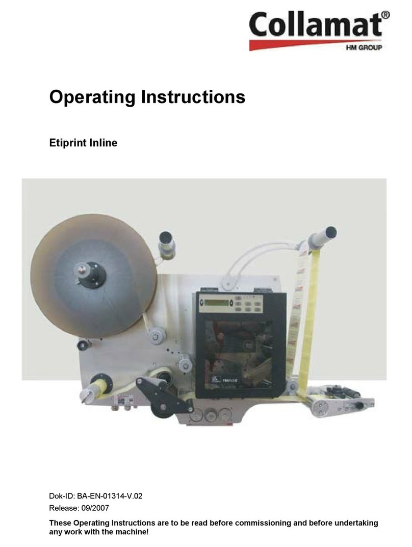
Collamat S Series Release Note

Inhalt
Technical Handbook
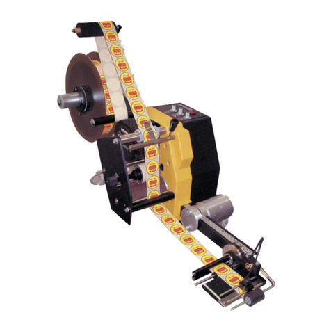
Collamat S Series
Doc. ID: TH-CO-S-EN
Release: V1.15/11/2013
The German-language version of this Technical Handbook is the only
official original version. Any Technical Handbook translated into other
languages (or excerpts of it) are only references to this original
version.
Read the Technical Handbook before performing any work on the machine!

2 Release: V1.15/05/2013
Technical Handbook
Translation of the Original Edition
SD: 28.11.2013 14:33
© Collamat AG
Etikettiersysteme
Bodenmattstrasse 34
4153 Reinach BL
Switzerland
Tel.: +41 (0) 61 756 28 - 28
Fax: +41 (0) 61 756 29 - 29
E-Mail: [email protected]
Internet: www.collamat.ch
Created by:
ps - Collamat AG
20-04-2010 V1.00 Draft for field testing devices - ps
10-05-2010 V1.01 Correction after translation – ps
20-09-2010 V1.02 Better pictures - ps
22-09-2010 V1.03 Update of chapter 6 - ps
25-09-2010 V1.04 Directory formatted - ps
27-09-2010 V1.05 Cable and Assembly – ps
14-01-2011 V1.06 Firmware updates and Debug – ps
03-02-2011 V1.08 Nonstop – ps
10-03-2011 V1.09 Firmware updates and read PIC Reg –ps
23-03-2011 V1.10 Cable + PCB (Index H) – ps
29-08-2011 V1.11 Set Output / Read Input for AVA changed - ps
22-11-2011 V1.12 Register J added - ps
22-12-2011 V1.13 Translations & corrections - ps
23-12-2011 V1.14 Translations & corrections – ps
27-11-2013 V1.15 Translation of nonstop part – Collamat S - ps

Collamat S Series
General
Release: V1.15/05/2013 3
1 General.......................................................................................................................................................6
1.1 Information about the Technical Handbook.........................................................................................6
2 Technology................................................................................................................................................7
2.1 Software/Firmware...............................................................................................................................7
2.2 The traction unit ...................................................................................................................................8
2.3 Components.........................................................................................................................................9
2.3.1 Front view .....................................................................................................................................9
2.3.2 Rear view....................................................................................................................................10
2.3.3 Front view traction unit................................................................................................................11
2.4 Assembly examples...........................................................................................................................12
2.4.1 General information’s to IP54 version ........................................................................................14
3 Components ............................................................................................................................................15
3.1 Construction.......................................................................................................................................15
3.2 Electronics - Control unit....................................................................................................................17
3.2.1 Details for the main control unit..................................................................................................20
3.2.2 Changing the main control unit...................................................................................................23
3.2.3 FIRMWARE versions..................................................................................................................24
3.4 The side connection plate “SIGNALS”...............................................................................................25
3.4.1 The „GSC“ M8-plug ....................................................................................................................27
3.4.2 The „PLC“ M8-plug .....................................................................................................................27
3.4.3 The „TACHO“ M12-plug.............................................................................................................27
3.5 Operator panel...................................................................................................................................28
3.6 The NDC06 motor controller (MC).....................................................................................................30
3.6.1 Changing the MC........................................................................................................................30
3.6.2 Settings for the MC.....................................................................................................................31
3.6.3 Status LED for the MC................................................................................................................32
3.6.4 Jumpers, LED, DIP and plugs of the MC....................................................................................32
3.7 FEED..................................................................................................................................................33
3.8 Controlling external devices...............................................................................................................34
3.9 Incremental encoder (optional) ..........................................................................................................37
3.9.1 Speed measurement ..................................................................................................................37
3.9.2 Hardware data for the incremental encoder...............................................................................38
3.10 Etikettierung - Theorie....................................................................................................................40
3.11 Electrical rewinder..........................................................................................................................44
3.11.1 Short description.........................................................................................................................44
3.11.2 Status LEDs on the MC ..............................................................................................................45
3.11.3 Electrical connections.................................................................................................................45
3.11.4 Voltage supply ............................................................................................................................47
3.11.5 Mechanics...................................................................................................................................47
3.1 Non-stop labeling...............................................................................................................................48
3.1.1 Short description.........................................................................................................................48
3.1.2 Assembly ....................................................................................................................................49

Collamat S Series
General
4 Release: V1.15/05/2013
3.1.3 Setup.......................................................................................................................................... 50
3.1.4 Nonstop Control-Table............................................................................................................... 51
3.1.5 Nonstop cabeling ....................................................................................................................... 52
4 Inputs + Outputs..................................................................................................................................... 53
4.1 Inputs + Outputs (Electronic)............................................................................................................. 53
4.1.1 Inputs ......................................................................................................................................... 53
4.1.2 Label sensor – inputs................................................................................................................. 56
4.1.3 Outputs....................................................................................................................................... 58
4.2 Inputs + Outputs (description)........................................................................................................... 61
4.2.1 Input details................................................................................................................................ 61
4.2.2 Output details............................................................................................................................. 64
5 Maintenance............................................................................................................................................ 66
5.1 Safety ................................................................................................................................................ 66
5.2 Maintenance schedule ...................................................................................................................... 68
5.3 Cleaning ............................................................................................................................................ 69
6 Faults, repair and maintenance work................................................................................................... 70
6.1 Safety ................................................................................................................................................ 70
6.2 Restarting after remediation of faults................................................................................................72
6.3 Table of faults.................................................................................................................................... 73
6.4 Performing maintenance and repair work.........................................................................................74
6.4.1 Replacing the pressure roller..................................................................................................... 75
6.4.2 Changing the traction cylinder ...................................................................................................76
6.4.3 Setting the belt tension (traction)...............................................................................................77
6.4.4 Changing the timing belt (traction).............................................................................................78
6.4.5 Changing the OOL spring ..........................................................................................................78
6.4.6 Changing the drive motor (traction) ...........................................................................................79
6.4.7 Ligth tube / Sender board replacement......................................................................................80
6.4.8 Adjusting the rewinder pendulum (RW active + passive)..........................................................81
6.4.9 Setting the belt tension (RW passive)........................................................................................82
6.4.10 Changing the timing belt (RW passive)......................................................................................83
6.4.11 Adjusting the friction clutch (RW passive)..................................................................................84
6.4.12 Reconditioning the clutch disks (RW passive)...........................................................................85
6.4.13 Setting the belt tension (RW active)...........................................................................................86
6.4.14 Changing the drive belt (RW active)..........................................................................................86
6.4.15 Changing the rewinder board (RW active).................................................................................87
6.4.16 Replacing Rewinder-Sensor-Board ersetzen (RW activ)...........................................................88
6.4.17 Changing the rewinder motor (RW active).................................................................................89
6.4.18 Replacing the mainboard (HMC0601) .......................................................................................90
6.4.19 Replacing the master controller (RCM4010) .............................................................................90
6.4.20 Firmware Update – Master-Controller (RCM4010)....................................................................91
6.4.21 Firmware Update – Slave-Controller (dsPIC) ...........................................................................92
6.4.22 Details to Menu - Service - Read PIC reg 0-63 .........................................................................96
6.4.23 Details to Menu - Service - Inputs..............................................................................................99
6.4.24 Details to Menu - Service – Read Outputs............................................................................... 100
Collamat S Series
General
Release: V1.15/05/2013 5
6.4.25 Details to Menu - Service - Set Outputs ...................................................................................101
6.4.26 Directions to naming of inputs/outputs .....................................................................................101
7 Index.......................................................................................................................................................102
8 Index of documents in the Appendix..................................................................................................103

Collamat S Series
General
6 Release: V1.15/05/2013
1 General
1.1 Information about the Technical Handbook
This Technical Handbook is a technically-detailed addendum to
the operating instructions for the Collamat S. All safety, warning
and caution notices in the Collamat S operating instructions are
also valid in this handbook with no restrictions.
The Collamat S Technical Handbook (abbreviated as TH in this
document) is considered the technical element of the operating
instructions. The TH should help you to use the Collamat S to its
fullest. The description of the individual mechanical and electrical
components also helps for rapid troubleshooting and problem
solving in case of faults. Any defective electronics modules
(printed circuit boards) are to be replaced as entire units and the
defective modules are to be sent to the Collamat AG company or
their representatives for repair or exchange. This is the only way
to ensure that the high level of quality of your Collamat S is
maintained after repairs.
The special features of the Collamat S include the following:
low-wear mechanics
minimal abrasive wear with the rewinder version
with friction clutch
robust, reliable and precise
simple handling with a modular structure
easy-to-adjust label brake
multiple options for installation (clamping pieces) in upright
or horizontal position
user-friendly thanks to modern, menu-based
programming
quickly configured to perform other labeling tasks
maximum labeling power
unwinder unit with a brake mechanism for 300 mm
or 400 mm diameter label rolls – optional with double
dancer
highly modern SMD technology
for 230 VAC / 115 VAC network current (adjustable
on the outside of the machine)
2-phase stepper motor with micro step resolution
for the greatest precision
various adapters for up to 3 cylinders (standard and
customer-specific)optional electrical rewinder
(for dispensing speeds > 50 m/min or for wide labels)
- DC motor with 4Q-MC and single- / double dancer control
optional external connection box / connection module
optional sensors for monitoring label
supply / rewinder volumes, ....
optional warning lamps (ready - error - maintenance)
optional Ethernet connection (standard / customer-specific)
customer-specific interface

Collamat S Series
Technology
Release: V1.15/05/2013 7
2 Technology
2.1 Software/Firmware
The control program for the Collamat S has the following
features:
dual processor hardware allows for rapid parallel
processing for communication and
drive control
modern user interface
preset and print run counter
impulse suppression for path-dependent suppression of the
label scanning for applications such as printed or
transparentlabels
impulse suppression for path-dependent suppression of the
goods scanning after labeling process
programmable settings for label position
programmable settings for pre-dispensing
multiple labeling with electronic adjustment of label offset
automatic adjustment of dispensing speed with
measurement of goods speed using an incremental encoder
storage of 99 labeling programs
password protection with multiple access levels
monitoring of almost empty label supply (LLO - optional) and
of out of label situation (OOL),
open counter-pressure roller in traction unit (TUO), rewinder
full (RWF - optional),
motordriver OK, ...
non-stop operation with 2 Collamat S systems = interruption-
free labeling
multilingual user interface
automatic setup of optical label sensor
all operational steps possible during labeling
control of all peripheral devices from the program - without
potentiometers, switches, etc .....
motorized (optional) rewinder unit for labeling
speeds > 40 - 50 m/min
infinitely adjustable paper brake
error / warning management - every exception status (input)
that could influence labeling can be configured
from the operator panel as an error, warning, or as a
situation to be ignored.

Collamat S Series
Technology
8 Release: V1.15/05/2013
2.2 The traction unit
Description The traction unit system is either attached directly using a
clamping piece connection or using a module rail on an adjustable
unit.
The corresponding peripheral devices are installed on the module
rail and / or on one of the many flanges on the housing.
All mechanical parts are surface-treated against corrosion.
The traction cylinder of the system is treated with a special coating
for permanent, slip-free drive transmission to the carrier paper.
The braking force of the label strip break is infinitely adjustable.
The traction cylinder can be easily turned by hand when the
dispenser is powered down (power OFF) to simplify setup of the
dispenser.
The rewinder drive system can be easily turned by hand to simplify
setup of the dispenser.
The pressure roller that holds the carrier paper on the traction
cylinder can be easily lifted (opened) using a turning knob for easy
setup of the dispenser.
When the pressure roller is open, this is displayed on the operator
panel (TUO - Error - corresponding warning message).
Uninterruptible labeling can be setup by installing the so called
Nonstop-Cabling-Set (two Collamat S are used – only one
incremental encoder will be used in speed mode: TACHO).
Several helpful options are available to increase the performance
and comfort of a Collamat S. These are the most important
options:
- Electrical rewinder unit (ERW)
- Indicator light column (red-green-orange) (SIG)
- Label volume (empty) observation (LLO)
- Rewinder volume (full) observation (RWF)
- Connection-Box (CBO)
- Connection-Module (CMO)
- Incremental-Encoder (TACHO)
- Magnet Flap Adapter (MFA)
- External Operator Panel (EOP)
- Double Dancer Rewinder
- Double Dancer Unwinder
- Lying Down Set
- Ø400mm Unwinder Disks
- div. clamps, modular rails adjusting units
- div. stands
- etc.

Collamat S Series
Technology
Release: V1.15/05/2013 9
2.3 Components
Description The individual components with their setup options and
maintenance are described here. This section begins with a
general overview of the dispenser.
The components are mounted on a module rail. Figure x shows
these components and their names mounted on the module rail:
2.3.1 Front view
Fig. 2-1
1 Pressure roller adapter
2 Dispensing edge adapter
3 Housing adapter
4 Clamping piece, 40 x 40 module rail
5 Side connection plate, "SIGNALS"
6 Pressure roller for traction cylinder
7 Paper brake opener
8 Operator Panel (keyboard and LCD)
9 Pendulum, feed roller unit
10 Unwinder unit
11 Unwinder front plate (adjustable)
12 Module rail
13 Traction cylinder
14 Rewinder pendulum
15 Rewinder cylinder
16 Side connection plate, "power"
1 3 5 7 6 8 9
2 4 12 13 14 15 16 10 11

Collamat S Series
Technology
10 Release: V1.15/05/2013
2.3.2 Rear view
Fig. 2-2
1 Pressure roller adapter
2 Dispensing edge adapter
3 Clamping piece module rail 40/40 x 50
4 Side connection plate, "SIGNALS"
8 Operator panel (keyboard and LCD)
9 Pendulum, feed roller unit
10 Unwinder unit
11 Unwinder front plate
16 Side connection plate, "power"
17 Adjustment wheel, dispenser applicator
18 Unwinder rear plate (fixed)
19 Dispenser edge angle adjustment (+ opt. spring
tension)
20 Unwinder pendulum spring tension adjustment
21 Traction unit housing
11 18 9
8 21 4 3 19 2 1
10 20 16

Collamat S Series
Technology
Release: V1.15/05/2013 11
2.3.3 Front view traction unit
Traction unit in
detail
Drive
1 Operator panel (keypad + LCD)
2 Paper brake opener
3 Paper brake
4 Side connection plate, "SIGNALS"
5 Pressure roller for traction cylinder
6 Module rail flange
7 Module rail
8 Traction cylinder
9 Rewinder pendulum
3
2
5
9
1
6
4
9
7
8
9

Collamat S Series
Technology
12 Release: V1.15/05/2013
2.4 Assembly examples
Description The modular structure of the Collamat S gives you nearly limitless
assembly options. The following assembly examples have
produced good labeling results.
Example 1 - Clamping piece on module rail
Example 2 - Clamping piece on housing floor
Example 3 Horizontal position of Collamat S - Clamping piece on housing floor

Collamat S Series
Technology
Release: V1.15/05/2013 13
Example 4 Horizontal position of Collamat S - Clamping piece on module rail
Example 5 Horizontal position of Collamat S - 2 clamping pieces on module rail
Example 6 – Collamat S "overhead" - clamping piece on housing floor or module rail

Collamat S Series
Technology
14 Release: V1.15/05/2013
2.4.1 General information’s to IP54 version
IP 54 variation
option
Example of a IP54 Installation with side labeling set, IP65 fork sensor (LSC) and fix
modular rail clamp piece (FXA)
Collamat S xx – 10 L – IP54
The side connection plate “SIGNALS” is available with or without D-SUB
connectors/plugs.
INFORMATION!
Pay attention to the different IP54 directions in the Collamat S
Series Operator Manual.
IP54 units have to be intensely maintained every 12 month (see also
chapter Maintenance in the Collamat S Series operator manual).

Collamat S Series
Components
Release: V1.15/05/2013 15
3 Components
Electric shock DANGER!
Before opening the traction unit (cover at rear),
pull the power cord from the device socket.
Stored capacitance inside the traction unit can
lead to electric shock. Because of this, wait at
least 10 seconds prior to opening the system.
3.1 Construction
Description The main control unit (HMC0601 Main board) and the traction
and rewinder mechanical systems of the Collamat®NG are
contained in a stable, attractive metal housing. Setup of software
parameters and monitoring of the spender are performed at the
operator panel. The Collamat S housing may only be opened for a
"one-time" setup and for service work.
Unscrew the four screws on the rear wall to open the housing
from the rear. The goods sensor type is configured using a jumper
on the connection board at the "SIGNALS" side connection plate
(see Configuring the Collamat S). The goods sensor connection is
set to PNP type by default.
After removing both side connection plates ("Power" and
"SIGNALS" connection plates - remove 4 screws from each and
unplug cables), the front plate can also be removed (remove the
front x assembly screws and pull the front plate out forwards). All
components of the Collamat S are attached to the front plate.
Service work is easiest to perform with the front plate removed.
The peripheral components are located outside the traction unit
housing:
The label unwinder unit is connected to the dispenser housing
using a special clamping piece (4 screws).
The label rewinder unit is located in the traction unit. The
capacity of the Collamat S rewinder is sized to fit carrier paper
from a 400 mm diameter label roll.
For rapid labeling (dispensing speed greater than 50 m/min) or for
very wide labels, an optional motorized rewinder is available.
This module consists of a 4-quadrant motor controller, a high-
torque DC motor, a sensor module (speed monitoring using
compensator control) and a special toroidal transformer with
additional winding for the motor controller.

Collamat S Series
Components
16 Release: V1.15/05/2013
Description (continued) To simplify feeding the carrier paper into the rewinder core, a
special combination module consisting of a friction clutch and
one-way bearing was developed. This ensures that the rewinder
coil is held at a perfect position despite reverse slippage.
Order text: Collamat S xx - WW D
(xx=max speed, WW=Width, D=Direction).
The pendulum of the rewinder damps the carrier paper
movement. With the optional motorized rewinder, the rewinder
pendulum assumes control of the rewinder speed.
The various adapter types (spring adapter, magnet flap adapter
(MFA), air vacuum adapter (AVA), etc.) are attached to the
40 x 40 module rail. The module rail itself is connected to the
dispenser housing using a special clamping piece. The control
and operator signals are connected to the adapter electronics in
the adapter housing using ribbon cable fed through the module
rail. The adapter electronics (depending on the adapter type,
various adapter boards are available) condition the label sensor
and the FEED button as well as, depending on the adapter type,
the sensor and actor signals.
The operator panel consists of a keypad, indicator LEDs and an
LCD display and is mounted to the upper guide roller of the feed
roller (turnable) by default.
Six keys, three LEDs and a 4-row x 20 character display (with
background lighting) allow for simple programming and monitoring
of the dispenser.
The operator panel can also be connected to the "SIGNALS"
connection plate. For this, the connection cable that normally
leads from the main control board to the operator panel is
attached to the free 5-pole plug of the connection board at the
"SIGNALS" connection plate.
For connecting the operator panel to the "SIGNALS" connection
plate (ext. operator), an additional connection cable is needed
(HMC06CA31A).
For installing the complete dispenser unit onto an adjustable
unit or an assembly unit, various clamping piece types are
available (module rail, housing floor, side bottom and side top).
See assembly examples at 3.1.

Collamat S Series
Components
Release: V1.15/05/2013 17
3.2 Electronics - Control unit
ESD DANGER!
The electronics of the control unit may not be
touched without taking precautions against ESD.
The electronics are sensitive to direct electrostatic
discharge.
Master controller The heart of the main control unit is a dual-processor system
consisting of a master controller and a slave controller.
The complete master controller unit is contained in a module that
is inserted into the main control unit (MHC0601-Mainboard). The
master controller communicates with the operator panel, the slave
controller and the peripheral components (SIGNALS connection
plate and adapter). The modern, powerful master controller leaves
nothing to be desired. Even with updated user and dispenser
firmware, the controller's computing power will remain sufficient for
the coming years. All components including Flash storage, RAM
(battery-buffered), interface controllers, real-time clock, RJ45 slot,
battery, etc. are located on this card module.
RCM 4010
Slave controller The slave controller executes the rapid dispenser functions
assigned by the master controller. The incremental encoder
(speed sensor), goods sensor, label sensor and motor controller
communicate directly with the slave controller.
The slave controller, power supply, interface controller and signal
conditioner are located on the main control unit. This is attached
to the front plate with four screws.

Collamat S Series
Components
18 Release: V1.15/05/2013
Motor controller The motor controller is a component developed and built by a
renowned step motor controller producer. Standard parameters
for using the Collamat S are 80V DC / 5.1/6A – 2000 steps /
revolution – automatic current reduction.
Power The power for the electronics is delivered by a high-powered
toroidal transformer. The rectification and regulation of the various
voltages (DC voltage production) is executed at the main control
unit and, optionally, at the rewinder module.
Slots An additional slot on the main control unit is for customer-
specific applications. Currently, the following add-on boards
(piggyback boards) are available:
X-WEB piggyback board: Controls a transverse belt
system
AVA piggyback board: Controls the various air vacuum
adapters
More add-on boards are planned.
Master controller - Main control unit

Collamat S Series
Components
Release: V1.15/05/2013 19
Measurements of the master controller and piggyback board
Print Modifications HMC0601V3-5 – 17.11.2011:
- R63, R64 = 560E
- C29 = 22uF/35V
- R14-19, R23-25, R29 = 560E
- J9, J10 = MSTBVA 2,5/ 2-G-5,08 (1755736)
- Heathsink – new drillings:
-Drawing 152188572
- New partlist:
Stückliste HMC0601-V3-5 - 52180260 vom 17112011.pdf
- New schematics:
HM-COLLAMAT RAB4010-V-3-5-Schema.pdf

Collamat S Series
Components
20 Release: V1.15/05/2013
3.2.1 Details for the main control unit
Connection terminals and plugs
No. Description Cable
J10 58V toroidal transformer, motor voltage, screw terminals 2 red wires
J9 27V toroidal transformer, logic voltage, screw terminals 2 blue wires
J13 Step motor, motor controller, power plug Cable with 2 cores
J12 Step motor, motor controller, control signal plug Cable with 8 cores
J7 Control signal plug, SIGNALS connection plate Cable with 40 cores
J4 OOL – plug – Out Of Label sensor Cable with 1 cores
J1 TUO – plug - traction unit open sensor Cable with 3 cores
J3 RWF – plug - ReWinder Full sensor Cable with 3 cores
J2 LLO – plug - paper supply low sensor Cable with 3 cores
J11 REW - plug - optional rewinder, control signals Cable with 6 cores
J6 Operator panel - plug - operator panel Cable with 5 cores
J8 Adapter plug - ribbon cable to adapter Cable with 10 cores
J5 Master controller - socket (microcontroller card) Cable with 40 cores
J14 Add-on board - plug - customer-specific boards Cable with xx cores
X3 PE Protective earth green - yellow
X4 PE Protective earth green - yellow
Fuses
No. Description Value
SI1 Microfuse 20 x 5 mm - (logic voltage - 24V DC, 5V DC and 3.3V DC) 2.5AT
SI2 Microfuse 20x5 mm - (step motor voltage - 80V DC) 5.0AT
F1 Electronic fuse (+24V F1 - ICH = 0.75A / IT = 1.5A)
F1 monitors the +24V that run on plugs J6, J7 and J8. 0.75 / 1.5A
F2 Electronic fuse (+24V F2 - ICH = 0.20A / IT = 0.4A)
F2 - This fuse is only used for the internal board test. 0.2 / 0.4A
This manual suits for next models
1
Table of contents
Other Collamat Label Maker manuals

Collamat
Collamat 9100 User manual

Collamat
Collamat 7600 User manual

Collamat
Collamat 9100 User manual

Collamat
Collamat C4300 Series Release Note

Collamat
Collamat 9100 Release Note

Collamat
Collamat 9100 Release Note

Collamat
Collamat 8600 User manual

Collamat
Collamat 6600 Release Note

Collamat
Collamat 3600 Release Note

Collamat
Collamat 8600 User manual