Coltene SciCan BRAVO G4 User manual

BRAVO™G4
Chamber Autoclave
SciCan
Operator’s Manual
- For US Customers Only -
97055179-1 | SD-634 US EN R1. BRAVO is a trademark of SciCan Ltd. A Coltene Group company

Manufactured for :
SciCan Ltd.
A Coltene Group Company
1440 Don Mills Rd.,
Toronto, ON, M3B 3P9 / CANADA
T +1-416-445-1600
TF +1-800-667-7733
customerservice@scican.com
1. FOREWORD 1
1.1 Symbols used 1
1.2 Symbols on the device 1
1.3 Relevant standards 1
1.4 Intended use 2
1.5 General warnings 2
1.6 Residual risks 3
1.7 Information on mitigation of residual risks 3
1.8 Network and data security 5
2. PACKAGE CONTENT 6
2.1 Dimension and weight 6
2.2 Description of the content 6
2.3 Product handling 7
2.4 Conditions for storage and transport 7
3. GENERAL DESCRIPTION - PRODUCT PRESENTATION 8
3.1 General characteristics 8
3.2 Technical specifications 9
3.3 Safety devices 11
3.4 Water supply characteristics 12
3.5 Front 13
3.6 Rear 14
3.7 LCD icons 14
3.8 Example of working cycle 15
4. SETTING UP THE DEVICE 16
4.1 Overall dimensions 16
4.2 Compartment dimensions for built-in installation 17
4.3 General precautions for installation 17
4.4 Power supply 18
4.5 Electrical connections 18
4.6 Direct connection to a centralized draining point 18
4.7 Anti-dust filter installation 19
5. FIRST START-UP 20
5.1 Starting 20
5.2 Main menu 22
5.3 Filling demineralized / distilled water 22
6. CONFIGURATION 23
6.1 Settings 23
7. PREPARATION OF THE MATERIAL 29
7.1 Treating the material before sterilization 29
7.2 Arranging the load 30
7.3 Positioning and use of tray holder support 32
8. STERILIZATION CYCLES 33
8.1 Extra drying 34
8.2 Delayed start 35
8.3 Execution of the cycle 36
8.4 Cycle outcome 36
8.5 Door opening at the end of the cycle 36
8.6 User-defined cycle 37
9. MATERIAL STORAGE 38

10. TEST PROGRAMS 39
10.1 B&D cycle 39
10.2 Vacuum test cycle 40
10.3 Vacuum test + B&D cycle 40
10.4 H2O test 41
10.5 Door opening 41
10.6 Manual interruption 42
11. USED WATER DRAIN 43
12. DATA MANAGEMENT & CONNECTIVITY 44
12.1 USB management 44
12.2 Wifi 46
12.3 Printers 48
12.4 Ethernet 49
12.5 G4 cloud 49
13. APPENDIX – PROGRAMS 50
13.1 Summary table of 17 - 120 v cycles 51
13.2 Summary table of 17 - 240 v cycles 53
13.3 Summary table of 22 - 120 v cycles 55
13.4 Summary table of 22 - 240 v cycles 57
13.5 Sterilization program diagram 60
13.6 Diagrams of the test programmes 62
13.7 Examples of printed reports 63
14. APPENDIX - MAINTENANCE 64
14.1 Regular maintenance programme 64
14.2 Scheduled maintenance messages 65
14.3 Description of maintenance interventions 66
14.4 Periodic sterilizer validation 69
14.5 Device useful life 69
14.6 Disposing the equipment when no longer used 69
15. APPENDIX - GENERAL PROBLEMS 70
15.1 Troubleshooting 70
16. APPENDIX – ALARMS 72
16.1 Alarm intervention 72
16.2 Alarm during a cycle 72
16.3 System reset 72
17. ALARM CODES 73
17.1 Errors (category E) 73
17.2 Alarms (category A) 75
17.3 Hazards (category H) 78
17.4 System errors (category S) 79
17.5 Troubleshooting 80
18. USER PIN RESET 88
19. APPENDIX - ACCESSORIES 88
20. PRINTER CONNECTION 88
21. APPENDIX - SPARE PARTS AND ACCESSORIES 89
22. APPENDIX - TECHNICAL SERVICE 89
23. APPENDIX - WARNINGS AND LOCAL REGULATIONS 89


1
1. FOREWORD
The instructions inform the user on how to properly operate the device. It is extremely important to read this
manual carefully and thoroughly before using the device.
This publication must not be reproduced, copied or transferred in any manner (electronically, mechanically, via
photocopies, translations or other means) without the prior written consent of the manufacturer.
The manufacturer has a company policy of continual development. Therefore, some of the instructions,
specifications and figures given in this manual may slightly differ from the purchased product. The
manufacturer reserves the right to make changes to this manual without giving prior notice.
The original text is in Italian; this is a translation from the original in Italian.
1.1 SYMBOLS USED
Type in Gray Box Pay particular attention to the paragraphs marked in a gray box.
Potential danger for people, environment and property.
Follow the procedures indicated in the manual to prevent potential damage to
materials, devices and/or property.
1.2 SYMBOLS ON THE DEVICE
Potential danger due to high temperature. Disposal in accordance with state/local
regulation.
I / O Switch ON / OFF. Refer to the User Manual.
Fuses 2xT15A 250V.
1.3 RELEVANT STANDARDS
The product described in this manual is manufactured in accordance with safety standards and doesn’t
represent any danger for the operator if used according to the following instructions.
The product is complying with the following standards as applicable:
IEC 61010-1:2010 + A1:2016, Safety requirements for electrical equipment for measurement, control, and
laboratory use, Part 1: General requirements.
IEC 61010-2-040:2015,
Safety requirements for electrical equipment for measurement, control, and
laboratory use, Part 2-040 Particular. requirements for sterilizers and washer-
disinfectors used to treat medical materials.
IEC 61326-1:2012, Electrical equipment for measurement, control and laboratory use – EMC
requirements, Part 1: General requirements.
IEC 62304:2006 + A1:2015, Medical device software - Software life-cycle processes.
ANSI/AAMI ST55:2016, Table top steam sterilizers.
ASME Boiler and Pressure Vessel Code Section VIII, Division 1
2xT15A 250V
Type in Gray Box

2
1.4 INTENDED USE
The product described in this manual is only intended for sterilization of reusable surgical instruments and
materials.
DEVICE INTENDED FOR PROFESSIONAL USE
The use of the device is strictly reserved to qualified personnel. It must never be used or handled by
untrained and/or unauthorized persons.
The device must not be used for the sterilization of fluids, liquids or pharmaceutical products.
The sterilizer is not a mobile or portable device.
1.4.1. IMPORTANT NOTES
Information contained in this manual is subject to change without notice.
The manufacturer is not responsible for direct, indirect or accidental damage resulting from or relating to the provision
or use of this information.
This document may not be reproduced, adapted or translated, in part or in full, without the prior written permission of
the manufacturer.
1.5 GENERAL WARNINGS
When using this product, always follow the instructions in the manual and never use it for anything other than
its intended purpose.
The user is responsible for any legal requirements relating to the installation and use of the product. The
manufacturer will not be held responsible for any breakage, malfunction, property damage or injury to people
in the event that the product is not installed or used correctly, or proper maintenance is not carried out.
Please observe the following precautions in order to avoid injury or property damage:
›Use ONLY demineralized / distilled water of high quality.
The use of water of inadequate quality can severely damage the device.
See technical characteristics appendix in this regard.
›DO NOT pour water or other fluids on the device.
›DO NOT pour flammable substances on the device.
›DO NOT use the system in the presence of flammable or explosive gases or vapours.
›Before performing any maintenance or cleaning intervention, ALWAYS DISCONNECT power supply.
Whenever it is not possible to disconnect the power
supply from the device, or if the external mains
switch is distant or not visible to the maintenance
technician, place a “work in progress” sign on the
external mains switch after having turned it off.
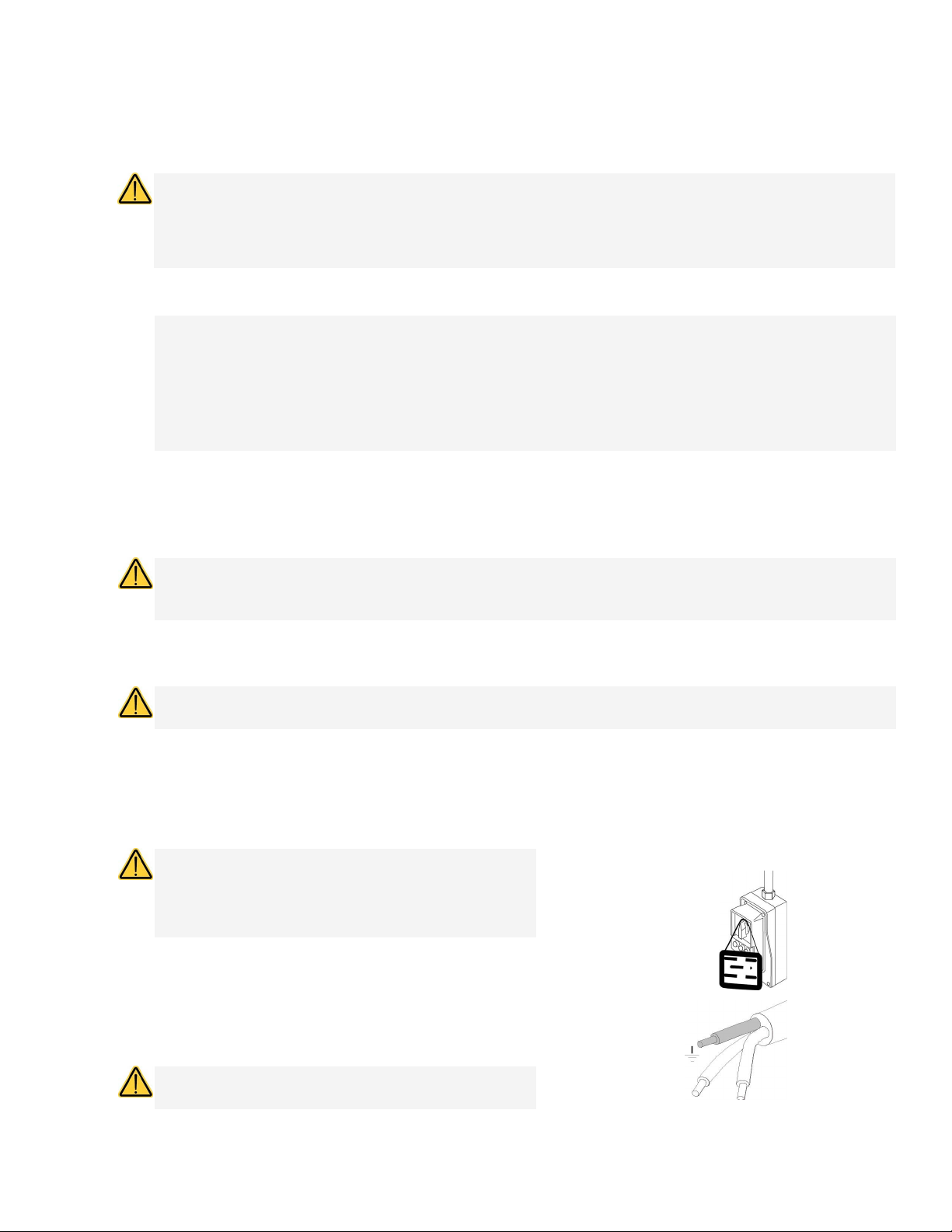
›Make sure the electrical system is grounded
according to current laws and/or standards.
›DO NOT remove any label or nameplate from the device;
request new ones, if necessary.
›Use ONLY original spare parts.
Failure to comply with the above exempts the
manufacturer from all liability.

3
1.6 RESIDUAL RISKS
FOR THE USER
›Contamination due to improper handling of the load.
›Burn by contact with hot surfaces or fluids.
FOR THE PATIENT
›Contamination due to unsterilized material caused by incorrect cleaning treatment before sterilization.
›Contamination due to implementation of incorrect reprocessing procedures.
›Contamination due to material unsuitable for sterilization or not compliant with instructions for use.
›Contamination due to unsterilized material caused by incorrect final assessment of sterilization process.
›Contamination due to missing or incorrect scheduled maintenance.
›Contamination due to missing periodic validation.
1.7 INFORMATION ON MITIGATION OF RESIDUAL RISKS
FOR THE USER
Contamination due to improper handling of the load.
See chapter PREPARING THE MATERIAL.
Burn by contact with hot surfaces or fluids.
To extract the sterile material, once the sterilization process has been completed with saturated steam at
121°C / 250°F or 132°C / 270°F, proceed as follows:
›Always wear PPE suitable for the handling of hot material and gloves of appropriate material and
thickness.
›Clean your gloved hands with a germicide detergent.
›Always use the special tray extractor, supplied as standard, to extract the trays from the sterilization
chamber.
›Avoid any contact of trays and material with contaminated and/or non-heat-resistant surfaces.
›Handle the sterile material making sure not to damage any packages, bags and containers serving as a
barrier.
FOR THE PATIENT
Contamination due to unsterilized material caused by incorrect cleaning treatment
before sterilization.
See chapter TREATING THE MATERIAL BEFORE STERILIZATION.
Contamination due to implementation of incorrect reprocessing procedures.
Make sure to use sterile material.
Contamination due to material unsuitable to sterilization or not compliant with
instructions for use.
›Check that the contaminated material is compatible with the selected sterilization process.

4
›Immediately separate the materials to be sterilized from those that must not be subjected to such
process or are not able to withstand it.
Contamination due to unsterilized material caused by incorrect final assessment of
sterilization process.
The sterilization process electronic control system monitors the various phases, at the same time checking that
the various parameters are respected; if any type of anomaly is encountered during the cycle, the program is
immediately interrupted, generating an alarm identified by a code, with a relative message explaining the nature
of the problem.
Furthermore, the sterilization process can be checked by means of:
CHEMICAL INDICATORS
That monitor the sterilization process by providing information, together with the control of physical and
biological parameters, on the conditions occurred in the sterilization chamber during the process.
The final toning of the process indicator does not certify that the product is sterile but only that the device has
been subjected to a sterilization process. If the toning does not occur, the operator in charge of releasing the
sterile material, that must not be used, must put all actions to avoid the use of the treated material.
PHYSICAL INDICATORS
They include the reading of machine data and the execution of specific tests indicated during the validation
phase for that specific cycle/load/autoclave. This control system can include:
›Direct reading of the synoptic system (thermometer, pressure gauge, recorder, etc.).
›Reading of prints/labels/files on which the data detected by the synoptic system are stored (parameters).
›Execution of specific tests (Vacuum test, Bowie Dick test) according to local guidelines.
The operator in charge of the process certifies the validity of the load at the end of every cycle by means of the
parametric release.
Contamination due to missing or incorrect scheduled maintenance.
The sterilizer, based on a preset programming, displays a warning message relating to the scheduled
maintenance necessary to ensure the good operation of the device.
Contamination due to missing periodic validation.
See chapter PERIODIC STERILIZER VALIDATION.

5
1.8 NETWORK AND DATA SECURITY
The BRAVO Sterilizer includes an Ethernet connection and a Wi-Fi module that allows the sterilizer to connect
to the local network and to useful services, including device troubleshooting and firmware updates.
The WiFi module supports IEEE 802.11 b,g,n with WEP, WPA, WPA2-PSK encryption standard in the 2.4 Ghz
range.
Since the security of the connection depends on the configuration of the wireless infrastructure (router or
access point), securing your Wi-Fi® connections is an important element of securing your data.
For maximum security, ensure your network is configured for WPA2 protection.
Avoid placing devices connected to your network in unsupervised public accessible places.
When using USB keys to download cycle data, check that the data has been copied in a supervised disk and
that regular backup plans are executed.
Tips on securing a new network
›Change the default network name (SSID) when installing new access points, routers, and gateways
›Change the administrative credentials (username and password) that control settings of your Access
Point / Router / Gateway
›Enable WPA2 Personal (aka WPA2-PSK) with AES encryption on all client devices
›Create a network passphrase that meets recommended guidelines
›Check a firewall is enabled and correctly configured
Checking securing of an existing network
›If your network is configured for an older generation of security (WEP or WPA) consider moving to WPA2
as soon as possible.
›Select an effective network passphrase. In general, increasing length, complexity and randomness all
improve the quality of a passphrase.
A passphrase should not contain a word found in a dictionary and should not include personal
information (identification number, name, address, etc).
›Periodically changing the passphrase on your network also increases security.
›Check proper handling of user accesses and logging on your infrastructure (PCs, devices, etc).
›Check a firewall is enabled and correctly configured.

6
2. PACKAGE CONTENT
Check the integrity of the product package upon receipt.
2.1 DIMENSION AND WEIGHT
Once the package is opened, check that:
›The supply matches the specifications of the
order (see the delivery note).
›There is no visible damage to the product.
In case of wrong delivery, missing parts or any type of damage, immediately inform in detail the reseller and the carrier
that made the delivery.
2.2 DESCRIPTION OF THE CONTENT
In addition to the sterilizer, the package contains:
1.
Dimensions and Weight
Height 600 mm / 23.62 in
Width 600 mm / 23.62 in
Depth 700 mm / 27.56 in
Total weight 68 kg / 149.91 lbs
1. Instrument trays: 5 pcs
2. Tray holder support
3. Operator’s documentation
4. Lubricant for door locking mechanism
5. Tray extractor
6. Additional bacteriological filter
7. Transparent silicone hose with quick
coupling, for manual water drainage
8. Elbow hose connector
9. Allen wrench (for manual door unlocking)
10. Grey plastic tube for direct drainage,
with fastening clamp, gasket, straight
fitting
11. Rear spacers
12. USB key, containing user’s manual
13. Bottle complete with silicone
transparent tube and quick coupling,
for manual water filling
14. Water filling funnel
15. Anti-dust filter

7
2.3 PRODUCT HANDLING
The packed product must be handled using, where possible, suitable mechanical means (lift truck,
pallet truck, etc.) and following the indications on the package.
In case of manual handling, the product must be lifted by two people using the suitable available
means.
Lift the product from the underneath on the sides.
Do not lift / hold the device by applying force to the door and its hinge.
Once the sterilizer has been removed from the package, it must be lifted by two people using the
suitable available means and handled, if possible, using a truck or similar.
We recommend to transporting and storing the device at a temperature not below 5° C (41° F). Extended
exposure to low temperatures may damage the product.
Store the original package and use it for any transport of the device. Using a different package may damage the
product during shipping.
Before transport, leave the device turned off for about 30 minutes after the last program finishes and
drain the filling and discharge tanks so that all the internal parts will have time to cool down.
2.4 CONDITIONS FOR STORAGE AND TRANSPORT
Temperature: between +5° C / +41° F and +70° C / +158° F
Humidity: between 20% and 80%
Pressure: between 50 and 110 kPa

8
3. GENERAL DESCRIPTION - PRODUCT PRESENTATION
3.1 GENERAL CHARACTERISTICS
The device is an electronic steam sterilizer, entirely operated by a micro-processor, with a large, moulded
stainless steel sterilization chamber.
It is characterized by an advanced fractionated vacuum system for the complete removal of air, even from
hollow, porous materials, and an effective final vacuum drying phase capable of eliminating all traces of
humidity from any load.
The exclusive steam generation system, the effective hydraulic circuit and the electronic management
(integrated by high-precision sensors) ensures high execution speed of process and an excellent stability of
thermodynamic parameters.
Moreover, its Process Evaluation System constantly monitors all the machine’s “vital” parameters in real-time,
guaranteeing absolute safety and a perfect result.
The device offers users 6 sterilization programs (one of which completely programmable), all equipped with
customizable, optimized drying for the effective sterilization of the various types of load (instruments and
materials) used in a medical environment.
All the cycles can be selected on the clear LCD screen, which also allows extensive configuration of the device
according to the user’s needs.
Like in the best tradition, the new range of autoclaves feature the most complete and advanced safety systems
available today, to ensure the user against any operation, electrical, mechanical, thermal or functional fault.
For the description of safety devices, refer to Technical Characteristics Appendix.

9
3.2 TECHNICAL SPECIFICATIONS
SUMMARY TABLE
Device STEAM STERILIZER
BRAVO G4 17 BRAVO G4 22
Manufactured for SciCan Ltd. A Coltene Group Company
1440 Don Mills Rd., Toronto, ON, Canada, M3B 3P9
Input voltage 240 V~ 60 Hz
120 V~ 60 Hz
Main fuses
(6.3 x 32 mm) (0.25 x 1.26 in) 2x T15A 250V
Electronic board fuses
(5 x 20 mm) (0.20 x 0.79 in) F1: T3.15A 250V (transformer primary 240 V~ 60 Hz / 120 V~ 60 Hz)
Nominal power 2300 W (for 240 V~)
1440 W (for 120 V~)
Insulation class Class I
Installation category Cat. II
Environmental operating
conditions
Indoor use
Temperature: +15°C (+59° F) ÷ +35°C (+95° F)
Relative humidity: between 20% and 80% max. non-condensing
Height: min -100 m ( - 328 ft) / max 3000 m (9842 ft) (above sea lev.)
Pollution degree max: 2
A-weighted sound power level
(ISO 3746) < 67 db (A)
External dimensions (HxWxD)
(rear connections excluded)
456 x 480 x 600 mm
17.95 x 18.90 x 23.62 in
Net weight: unladen approx. 49.60 kg / 109.34 approx. 51.30 kg / 113.09
Net weight: unladen, with tray
holder support and trays approx. 51 kg / 112.44 lbs approx. 53 kg / 116.84
Net weight: unladen,
with tray holder support, trays
and water at MAX. level
approx. 56.50 kg / 124.56 approx. 58.50 kg / 128.97
Sterilization chamber
dimensions
(D x D)
250 x 350 mm
9.84 x 13.78 in
250 x 450 mm
9.84 x 17.72 in
Sterilization chamber total
volume
approx. 17 L
(0.017 cu. m)
approx. 22 L
(0.022 cu. m)
Sterilization chamber usable
volume (with tray holder
support inserted)
approx. 10 L
(0.010 cu. m)
approx. 13 L
(0.013 cu. m)
Sterilization chamber usable
dimensions
17 L (1.38x1.55x2.97) dm /
6.4 cu. dm
22 L (1.38x1.55x3.97) dm /
8.5 cu. dm
Water tank capacity (filling) approx. 5.5 L (water at MAX. level)
approx. 1 L (water at MIN. level)
Sterilization programs 5 standard programs + 1 program defined by the user

10
Device STEAM STERILIZER
BRAVO G4 17 BRAVO G4 22
Test programs
B&D Test
Vacuum Test
Vacuum Test + B&D Test
Pre-heating time(from cold) approx. 10 min.
USB connection
Key capacity lower than or equal to 2GB: FAT formatting with 16K/
sector
Keys capacity higher than 2GB:
FAT32 formatting with 16K/sector
Printer connection * Serial RS232 (printer cable max. length 2.5 m – 8.20 ft)
240 V 60 Hz Main power cord
Plug NEMA 6-15P 250V-15A
SJT 14 AWG / 3C 300V 60° C (140° F)
Connector C19 acc. to IEC 60320
120 V 60 Hz Main power cord
Plug NEMA 5-15 125 V-15A
Cable SJT 14 AWG / 3C STYLE 1015 60° C (140° F)
Connector C19 acc. to IEC 60320
Ethernet connection RJ45 (max. cable length 29 m – 95.14 ft)
WiFi 802.11 b/g/n (2.4 Ghz); WEP / WPA / WPA2-PSK encryption
Bacteriological filter (filter
element in PTFE)
Porosity: 0.027 microns
Connection: male connector 1/8” NPT
Maximum flow of drained water 1 L/min.
Temperature of drained water 50° C / 122° F
Max. temperature of drained
water 90° C / 194° F
Total heat in Joule sent by the
sterilizer to the surrounding air
in 1 hour of continue operation
17 L = 3.6 MJ 22 L = 4 MJ
Manoeuvre/handling space 1 m x 1 m
3.28 x 3.28 ft
Device BRAVO G4 17 BRAVO G4 22
Working pressure -0.8 ÷ 2.4 bar -0.8 ÷ 2.4 bar
Safety device setting 2.4 bar 2.4 bar
* The optional external printers Ref. M7D200012 is compatible with the BRAVO G4.
Refer to the printer manual for printer startup and paper loading.

11
3.3 SAFETY DEVICES
The sterilizer is equipped with the following safety devices for which we provide a brief description of their
function:
›Mains fuses (see data in summary table)
Protection of the whole device against possible failures of heating elements.
Action: power supply interruption.
›Electronic circuit protection fuses (see data in summary table)
Protection against possible failures of the primary circuit of the transformer and of low voltage users.
Action: interruption of one or more low voltage circuits.
›Thermal circuit-breakers on mains voltage windings
Protection against possible overheating of pump motors and of transformer primary winding.
Action: temporary cut-off (until cooling) of the winding.
›Safety valve
Protection against overpressure in the sterilization chamber.
Action: release of the steam and restoration of the safety pressure.
›Safety thermostat with steam generator manual reset
Protection against steam generator overheating.
Action: cut-off of the electricity to the steam generator.
›Safety thermostat with chamber heating element manual reset
Protection against overheating of the heating elements of the container under pressure.
Action: cut-off of the electricity to the chamber heating element.
›Door position safety microswitch
Confirmation of the correct closing position of the door of the container under pressure.
Action: signalling of wrong door position.
›Motor-driven door lock mechanism with electromechanical protection (pressure
switch)
Protection against accidental opening of the door (even in a blackout).
Action: prevents accidental opening of the door during a program.
›Door locking mechanism safety microswitch
Striker for the correct closing position of door locking system.
Action: signalling of failed or wrong operation of door locking mechanism.
›Self-levelling hydraulic system
Plumbing system structure for the spontaneous levelling of the pressure in the case of a manual
interruption of the cycle, alarm or blackout.
Action: automatic restoration of atmospheric pressure in the sterilization chamber.
› Integrated system for evaluating the sterilization process
Continuous verification of the sterilization process parameters entirely managed by microprocessor.
Action: immediate interruption of the program (in case of malfunction) and generation of alarms.
›Sterilizer operation monitoring
Real-time oversight of all significant parameters when the machine is powered.
Action: generation of alarm messages (in the case of anomaly) with possible interruption of the cycle.

12
3.4 WATER SUPPLY CHARACTERISTICS
Only use demineralized / distilled water having the following characteristics to supply the sterilizer.
Description Values in the Water Supply Values Inside Residual
Dry Condensate < 10 mg/L < 1 mg/L
Silicone Oxide SiO2 < 1 mg/L < 0.1 mg/L
Iron < 0.2 mg/L < 0.1 mg/L
Cadmium < 0.005 mg/L < 0.005 mg/L
Lead < 0.05 mg/L < 0.05 mg/L
Heavy Metal Residues (Iron,
Cadmium and Lead Excluded) < 0.1 mg/L < 0.1 mg/L
Chlorides < 2 mg/L < 0.1 mg/L
Phosphates < 0.5 mg/L < 0.1 mg/L
Conductivity At 20° C / 68° F < 15 µS/cm < 3 µS/cm
pH Value 5 - 7 5 - 7
Aspect colourless, transparent, without
sediment
colourless, transparent,
without sediment
Hardness < 0.02 mmol/L < 0.02 mmol/L
When buying demineralized / distilled water, make always sure that the quality and characteristics declared by the
manufacturer are compatible with those specified in the table.
The use of water for steam generation with presence of contaminantswith levels exceeding those
indicated in the above table can greatly shorten sterilizer lifetime.
This could also result in an increase of oxidation in the most sensitive materials as well as in an increase
of limescale residues on generator, boiler, internal supports, trays and instruments.

13
3.5 FRONT
1. Model
2. Control panel and LCD screen
3. Door
4. Power switch
5. Anti-dust filter
1. Sterilization chamber
2. Bacteriological filter
3. Door locking system
4. Water drainage filter
5. Front filling quick connector
6. Clean water reservoir drainage quick
connector
7. Waste water drainage quick connector
8. Door
9. Steam diffuser

14
3.6 REAR
1. Fastening slots for rear spacers
2. Heat exchanger
3. Connection for direct water drainage
4. Connection for automatic demineralized /
distilled water filling (only for H2O AUX EV kit
(AUX SV) and automatic filling accessory kit)
5. Data plate
SERIAL NUMBER LABEL (See image *)
6. Ethernet cable connection (max. length 29 m /
95,1444 ft)
7. Serial cable connection
8. Automatic filling electrical connection (only for
H2O AUX EV kit (AUX SV) and automatic filling
accessory kit)
9. Network fuses
10. Power cable connection
3.7 LCD ICONS
The screens in the following pictures may vary in shapes and colours, but their contents are the same as shown on the
sterilizer display.
1. Selection for data management & connectivity
2. Selection of sterilization and test cycles
3. Time and date
4. Button for quick download of new cycles
5. System info selection
6. Door unlock
7. Selection of the sterilizer settings (Setup)
*

15
3.8 EXAMPLE OF WORKING CYCLE
The sterilization program can be effectively described as a succession of phases, each one with a very precise
objective.
For example, a B CYCLE program: after loading the material in the chamber, closing the door, selecting the
program and starting the cycle (after locking the door opening mechanism), the following sequence will occur
(see the graph below):
1. Steam generator and sterilization chamber pre-heating.
2. Air removal and steam penetration in the material through a series of vacuum (extraction of air and fluid
from the sterilization chamber) and pressure (injection of steam into the chamber) phases.
3. Pressure rises with the consequent increase in the temperature of the steam, until reaching the
conditions required for sterilization (in the example, 132° C / 269.6° F).
4. Pressure and temperature stabilization.
5. Load sterilization for the required time (in the example, 4 minutes).
6. Sterilization chamber depressurization.
7. Vacuum drying phase.
8. Load ventilation, by means of sterile air.
9. Pressure levelling, bringing the sterilization chamber back to the atmospheric pressure level.
Having reached this last phase, you can unlock the door and remove the load from the sterilization chamber.
It should be emphasized that phases 1, 3, 4, 6 and 9 are identical in all cycles, with slight variations of duration
that are solely dependent on the quantity and consistency of the load and the heating conditions of the
sterilizer while phases 2, 5, 7 and 8 clearly vary their configuration and/or duration on the basis of the cycle
selected (and, as a consequence, the type of load) and the choices made by the user.
Please refer to the Programs Appendix for more details on programs.
A PRESSURE (BAR)
B PROCESS
C TIME (MIN)
D FRACTIONATED VACUUM
E LONG DRYING

16
4. SETTING UP THE DEVICE
The safety of every system which integrates the device is the responsibility of the system assembler.
The first and essential step for a proper operation of the sterilizer, its durability over time and complete use of
its features, is a correct and careful commissioning. Moreover, this precaution will avoid the danger of physical
injury or property damage, not to mention malfunctions and damage to the device.
Please meticulously follow the instructions contained hereafter in this chapter.
Technical Service department (see appendix) is available for further information.
The sterilizer is placed on the market only after having passed all the checks required. It does not require any additional
calibration for commissioning.
4.1 OVERALL DIMENSIONS
Centre distance and maximum overall dimensions of the sterilizer feet, with and without rear spacers (mm/in):
A Feet B Rear spacers
Dimensions and Weight 17 L 22 L
AHeight (total) 456 mm / 17.95 in
BWidth (total) 480 mm / 18.90 in
C
Depth (excluding rear
connections)
Note: the sterilizer can be
positioned on a surface only
550 mm / 21.65 in deep
600 mm / 23.62 in
Total weight (device only - no
trays or holder, no water)
49.60 kg /
110. 23 lbs
51.30 kg /
113.0 9 lbs
Total weight (max. load, including
trays & holder, max. clean water)
62.50 kg /
137.78 lbs
66 kg /
145.50 lbs
Other manuals for SciCan BRAVO G4
3
Table of contents
Other Coltene Dental Equipment manuals

Coltene
Coltene Coltolux LED User manual

Coltene
Coltene CanalPro Apex Locator Compact User manual

Coltene
Coltene SciCan BRAVO G4 User manual

Coltene
Coltene ParaPost XT P-680T User manual

Coltene
Coltene CanalPro Jeni User manual

Coltene
Coltene CanalPro CL2 User manual

Coltene
Coltene ParaPost X Series User manual

Coltene
Coltene CanalPro CL User manual

Coltene
Coltene CanalPro User manual

Coltene
Coltene SciCan STATIM B G4+ User manual